1
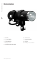
Profoto B1 500 AirTTL User´s Guide 2 www.profoto.com Profoto B1 500 Air TTL Profoto B1 500 Air TTL Congratulations on your new Profoto product! Regardless if you chose a new flash or a new light-shaping tool, know that almost half a century’s worth of experience was put into its making. If the years have taught us one thing, it is to never neglect a single detail. We only put our name on a product in which we have the fullest confidence. Before shipping, every one of our products pass an extensive and strict testing program. Unless it complies with the specified performance, quality and safety, it is a no-go. As a result, we are confident that your new Profoto product will stay with you for years and help you grow as a photographer. But getting the product is only the beginning of that journey. Using it for light shaping is the real adventure. That is why we take pride in providing you with such a wide assortment of lightshaping tools, allowing you to shape the light in any way you can imagine. The almost infinite possibilities might seem bewildering at first, but we’re certain you will soon get the hang of it. Still, I encourage you to sign up for our newsletter at www.profoto.com/newsletter or visit our blog at www.profoto.com/blog so that we can share our experience from almost 50 years of light shaping and hopefully inspire you to grow even further. Enjoy your Profoto product! Conny Dufgran, founder www.profoto.com 3 Profoto B1 500 Air TTL 4 General safety instructions Safety Precautions! Do not operate the equipment before studying the instruction manual and the accompanying safety information. Make sure that Profoto Safety Instructions always accompany the equipment! Profoto products are intended for professional use! Generators, lamp heads and accessories are intended for indoor photographic use only. Do not place or use the equipment where it can be exposed to moisture, extreme electromagnetic fields, or in areas with flammable gases or dust! Do not expose the equipment to dripping or splashing. Do not place any objects filled with liquids, such as vases, on or near the equipment. Do not expose the equipment to rapid temperature changes in humid conditions as this could lead to condensation water in the unit. Do not connect this equipment to flash equipment from other brands. Do not use flash heads without supplied protective glass covers or protective grids. Glass covers must be changed if they have become visibly damaged to such an extent that their effectiveness is impaired, for example by cracks or deep scratches. Lamps must be changed if they are damaged or thermally deformed. When placing a lamp into the holder ensure not to touch the bulb with bare hands. Equipment must only be serviced, modified or repaired by authorized and competent service personnel! Warning The terminals marked with the flash symbol are hazardous when live. WARNING – Electrical Shock – High Voltage! Mains powered generators shall always be connected to a mains socket outlet with a protective earthing connection! Only use Profoto extension cables! Do not open or disassemble generators or lamp heads! Equipment operates with high voltage. Generator capacitors are electrically charged for a considerable length of time after being turned off. Do not touch modeling lamps or flash tubes when mounting an umbrella metal shaft in its reflector hole. Disconnect the lamp head cable between the generator and lamp head when changing the modeling lamp or flash tube! The mains plug or appliance coupler is used as disconnect device. The disconnect device shall remain readily operable. Batteries (battery pack or batteries installed) shall not be exposed to excessive heat such as direct sunlight, fire, or the like. Caution – Burn Hazard – Hot Parts! Do not touch hot parts with bare fingers! Modeling lamps, flash tubes and certain metal parts emit strong heat when used! Do not point modeling lamps or flash tubes too close to people. All lamps may on rare occasions explode and throw out hot particles! Make sure that the rated voltage for the modeling lamp corresponds with the technical data in the user guide regarding the power supply! NOTICE – Equipment Overheating Risk Remove transport cap from lamp head before use! Do not obstruct ventilation by placing filters, diffusing materials, etc. over inlets and outlets of the equipment ventilation or directly over glass covers, modeling lamps or flash tubes! Note about RF! This equipment makes use of the radio spectrum and emits radio frequency energy. Proper care should be taken when the device is integrated in systems. Make sure that all specifications within this document are followed, especially those concerning operating temperature and supply voltage range. Make sure the device is operated according to local regulations. The frequency spectrum this device is using is shared with other users. Interference cannot be ruled out. Final Disposal Equipment contains electrical and electronic components that could be harmful to the environment. Equipment may be returned to Profoto distributors free of charge for recycling according to WEEE. Follow local legal requirements for separate disposal of waste, for instance WEEE directive for electrical and electronic equipment on the European market, when product life has ended! www.profoto.com Congratulations on your new Profoto product!............................................................3 General safety instructions.........................................................................................4 Nomenclature............................................................................................................6 Operation...................................................................................................................9 Quick guide..................................................................................................9 Power on/off.................................................................................................9 Select Freeze/Normal mode........................................................................10 Set light output (Energy).............................................................................10 Select Sync setting.....................................................................................11 Modeling light settings................................................................................12 Ready signal settings..................................................................................12 Handling..................................................................................................................14 Battery mounting........................................................................................14 Battery charging.........................................................................................14 Stand mounting..........................................................................................14 Mounting Profoto Light Shaping Tools.........................................................14 Replacing the Reflector/Front glass.............................................................15 Changing flash tube and Model Light LED...................................................15 Other.......................................................................................................................16 Automatic flash exposure (TTL) indicator....................................................16 Temperature limit indicator.........................................................................16 Check Firmware.........................................................................................16 Upgrade Firmware......................................................................................16 www.profoto.com Profoto B1 500 Air TTL Table of Contents 5 Profoto B1 500 Air TTL Nomenclature 7 7 8 5 6 8 6 9 9 1 2 3 4 1. Handle 6. Zoom scale 2. Tilt-lock knob 7. Umbrella holder 3. Stand adapter 8. Battery 4. Clamp screw 9. Battery release button 5. Reflector and Front glass www.profoto.com Profoto B1 500 Air TTL 10 7 11 12 10.USB port 12.IR-Slave eye 11.Sync connector 13 14 15 18 16 17 13.LCD display 16.ENERGY/SETTINGS dial 14.MODEL button 17.READY button 15.TEST button 18.SYNC button www.profoto.com Profoto B1 500 Air TTL 23 24 FREEZE 25 ! 26 AUTO 22 MODEL READY SYNC PROP FREE DIM BEEP SLAVE % 19 8 20 AIR 21 24. Freeze mode indicator 19. Modeling light setting 20. Ready signal setting 25. Temperature limit indicator 21. Sync/Air setting 26. Automatic flash exposure (TTL) indicator 22. Battery level indicator 23. Light output setting 27 27. Battery charger 28. Case (Bag XS) 28 www.profoto.com Profoto B1 500 Air TTL Operation Quick guide For detailed operating instructions, see subsequent sections. 1. Charge the battery (see page 14). 2. Mount the battery (see page 14). 3. Remove the transport cap from the Reflector/Front glass [5]. 4. Fit the Stand adapter [3] to a light stand and secure it with the Clamp screw [4] (see page 14). 5. Adjust the tilt position of the flash by loosening the Tilt-lock knob [2] (see page 14). 6. Switch on the unit by pressing and holding the TEST button [15] (see page 10). 7. Select Freeze/Normal mode by pressing and holding the ENERGY/SETTINGS dial [16] and then shortly pressing the TEST button [15] (see page 11). 8. Set the briefly flash light output with ENERGY/SETTINGS dial [16] (see page 11). 9. Release a test flash by pressing the TEST button [15] (see page 11). 10.Select Sync setting [21] with the SYNC button [18] (see page 12). 11.Select Modeling light setting [19] with the MODEL button [14] (see page 13). 12.Select Ready signal setting [20] with the READY button [17] (see page 13). 13.Mount Light Shaping Tools (see page 15). Power on/off 1.To switch on the unit, press and hold down the TEST button [15] until the Display [13] shows the settings information. 2. To switch off the unit, press and hold down the TEST button [15] until the Display [13] is all black. The B1 unit automatically goes into sleep after 30 minutes and shuts off completely after one hour of inactivity to save battery life. www.profoto.com 9 Profoto B1 500 Air TTL 10 Select Freeze/Normal mode The B1 unit can operate in two modes to maximize the versatility in different shooting situations. • Normal mode: Optimized color temperature stability over the entire energy range. Best option for most types of shots. • Freeze mode: Optimized for shortest flash duration. Best option for shots where the flash is used to freeze fast action. Switch between Freeze/Normal mode by pressing and holding the ENERGY/SETTINGS dial [16] and then shortly pressing the TEST button [15]. When Freeze mode is selected, the Freeze mode indicator [24] is shown on the Display [13]. See below overview of flash duration in Freeze vs. Normal mode. Set light output (Energy) The light output of the flash light is shown on the Display [13] in a relative f-stop scale. The maximum energy (500Ws) is shown as 10. Use the ENERGY/SETTINGS dial [16] to change the energy level of the flash light: • Turn the ENERGY/SETTINGS dial [16] to change the energy level in 1/10 f-stop increments. • Press and turn the ENERGY/SETTINGS dial [16] to change the energy level in 1 f-stop increments. The TEST button [15] is illuminated when the unit is fully charged and ready to flash. Press the TEST button [15] to release a test flash. www.profoto.com Wireless sync settings: • AIR: The built-in Profoto Air receiver is activated. The B1 is set to be triggered and/or controlled from any of the optional Profoto Air transceivers offered by Profoto. • SLAVE: The built-in IR-Slave eye [12] is activated. The flash will slave sync if another flash is fired or an IR signal is detected. Profoto B1 500 Air TTL Select Sync setting The current sync setting is shown in the Sync/Air setting section [21] on the Display [13]: Cable sync only: • Blank: When the Sync setting shows blank, the B1 can only be synced with cable. Activate/deactivate the wireless sync settings by briefly pressing the SYNC button [18]. To toggle between the wireless sync options, press and hold the SYNC button [18]. Air (and TTL) operation When ‘AIR’ is selected in the Sync/Air setting section [21] on the Display [13], the B1 is set to be triggered and/or controlled from any of the optional Profoto Air transceivers offered by Profoto. The B1 supports all available Air accessories offered by Profoto including those listed in the table below. 1. Activate Air by following the instructions to Select Sync Setting. 2. When Air is activated, press and hold down the SYNC button [18] until the channel and group setting in the Sync/Air setting section [21] is blinking and then release the button. 3. Press and turn the ENERGY/SETTINGS dial [16] to change the channel. 4. Turn the ENERGY/SETTINGS dial [16] to change the group. Note: There are eight different channels (1-8) that can be set, and each channel has 6 groups (A-F). All lights set to the same channel will be synced together. Groups are used to remotely control individual lights or groups of lights on the same channel when a set-up is made with more than one light. Air Accessories compatible with B1 (For operation instruction refer to user guide of respective accessory). Optional Profoto Air accessories Usable features in combination with B1 500 AirTTL Flash sync Remote control TTL (Automatic flash setting) Air TTL-C/N* X X X Air Remote TTL-C/N* X X Air Sync* X Air USB** X *Optional Camera mounted transmitters ** Dongle for using Profoto Air Software www.profoto.com 11 Profoto B1 500 Air TTL 12 Slave Sync operation When ‘Slave’ is shown in the Sync/Air setting section [21] on the Display [13], the B1 unit senses the flash release, as well as IR signals from most IR sync transmitters. 1. If the Sync/Air setting section [21] is blank, press the SYNC button [18] once to activate wireless sync. ‘AIR’ or ‘Slave’ is now displayed. 2. Ensure that ‘Slave’ is displayed. If not, press and hold the SYNC button [18] until ‘Slave’ is displayed. Cable Sync operation Sync via cable is possible in all sync modes. Connect a sync cable from the camera or flash meter to the Sync Connector [11] on the B1 unit. Modeling light settings The current setting is shown in the Modeling light setting section [19] on the Display [13]. 1. Press the MODEL button [14] to turn the modeling light on or off. 2.With the modeling light on, press and hold down the MODEL button [14] to toggle between ‘PROP’ and ‘FREE’: • PROP: The modeling light intensity is automatically adjusted to be proportional to the selected energy level of the flash light. • FREE: The modeling light intensity is manually set, independent from the energy level of the flash light. 3.If ‘FREE’ is selected: With the modeling light on, press and hold down the MODEL button [14] until the percentage value is blinking. Turn the ENERGY/SETTINGS dial [16] to change the percentage value. After a few seconds, the display will stop blinking and the new value will be set. Ready signal settings The current setting is shown in the Ready signal setting section [20] on the Display [13]: • BEEP: The unit beeps when it is ready to flash again after recharging. • DIM: The modeling light is turned off after flashing, and is turned on when it is ready to flash again. • DIM BEEP: The modeling light is turned off after flashing. The unit beeps and the modeling light is turned on when it is ready to flash again. • Blank: No ready signal. Use the READY button [17] to select the Ready signal setting: • Press the READY button [17] to turn ‘BEEP’ on or off. • Press and hold down the READY button [17] to turn ‘DIM’ on or off. www.profoto.com The sound alarm is partially deactivated when BEEP is deactivated. If BEEP is deactivated the sound alarm will only go off if B1 is used in TTL operation and cannot keep up with the camera in sequence shooting. Quick burst Quick burst is an automatically activated function that allows a series (burst) of flashes to be fired at a faster pace than the B1 can recharge, without losing light output. The function is only active when the light output is set to less than full. The length of the burst, in number of flashes, depends on the repetition rate and the set light output. The lower the light output is set, the longer bursts can be triggered. Thanks to this feature, the B1 can trigger up to 20 flashes per second on lower power output without triggering the “Wrong exposure alarm”. Note that the accuracy of the light output is slightly less precise when Quick burst is active. www.profoto.com Profoto B1 500 Air TTL Wrong exposure alarm When a flash is released before the unit is ready, there will be a long beep and the display will blink. These signals indicate that the flash light does not fully correspond to the set value. The B1 will always continue to flash even if the set light output cannot be met as the image may still be usable if the catch of the moment was perfect. 13 Profoto B1 500 Air TTL 14 Handling Battery mounting 1. To mount the battery, fit the battery pack into the B1 unit and push firmly until the battery pack locks in place. Make sure there is a “click” sound, indicating that the battery pack is properly secured. 2. To dismount the battery, first switch off the B1 unit. Press the Battery release button [9] and pull out the battery pack. Battery charging For optimal performance, the battery should be fully charged prior to usage. The battery can be charged from any charge level. Only use the Profoto Battery Charger 2.8A, Profoto Battery Charger 4.5A, or Profoto Car Charger 1.8A. If the battery has not been used for a long time, the Profoto Battery Charger 2.8A should preferably be used. The Profoto Battery Charger 4.5A could be used, but puts more wear on a deeply discharged battery. The Profoto Car Charger 1.8A should not be used in this case. 1. Dismount the battery. 2. Connect the battery charger to the battery pack. 3. Check that the battery charger indicates that charging is in progress. 4. When the battery charger indicates that the charging is completed, it is recommended to disconnect the battery charger and remove the battery from the charger. Stand mounting 1. Fit the Stand adapter [3] to a light stand and secure it with the Clamp screw [4]. 2. The B1 unit can be directed upwards/downwards when the Tilt-lock knob [2] is loosened. Fasten the Tilt-lock knob [2] when the unit is correctly directed. Mounting Profoto Light Shaping Tools The B1’s built-in reflector creates a wide and even light spread with a high output. In addition, the B1 is compatible with more than 120 light shaping tools, which can be used to shape its already beautiful light into almost any light you can imagine. All tools with standard reflector mount (rubber collar with clasp) Most reflectors are equipped with Profoto’s unique clamp mechanism, which makes them easy to mount and allows you to shape the light by simply sliding the reflector back and forth along the zoom scale [6]. 1. Unlock the clasp on the reflector. 2. Slide the reflector onto the B1. Use the zoom scale [6] to place the reflector in the desired position. 3. Secure by locking the clasp on the reflector. www.profoto.com 1. Slide the umbrella shaft into the Umbrella holder [7]. 2. After a few centimeters, there will be more friction, then continue to slide the umbrella shaft a few more centimeters into the Umbrella holder [7]. Profoto B1 500 Air TTL Umbrella mounting Umbrellas are simply mounted by sliding the umbrella shaft into the Umbrella holder [7]. The diameter of the umbrella shaft must be between 7 mm and 8 mm in order to fit. When an umbrella is used, it is not possible to mount an external reflector at the same time. Replacing the Front glass The Front glass [5] can be replaced with optional front glass or glass domes. Domes can be used to enhance the “zoom effect” if using any of Profoto’s “zoomable” reflectors. 1. Switch off the B1 and remove the battery. 2. Wait five minutes to allow the unit to be fully discharged and cooled down. 3. Gently remove the Front glass [5] by pushing the springs holding the glass gently to the sides. 4. Carefully fit the front glass/glass dome in place. Make sure that all springs holding the glass are back in position and securely holding the front glass/glass dome. Changing flash tube and Model Light LED For replacement of the modeling light LED or Model Light LED, contact your local dealer or distributor for professional service. www.profoto.com 15 Profoto B1 500 Air TTL 16 Other Automatic flash exposure (TTL) indicator The automatic flash exposure (TTL) indicator [26] is lit every time the flash output is set automatically by the camera. This will only happen when the B1 is operated together with any of the optional Air Remote TTL-C/N in TTL mode. The indicator is lit for a few seconds after receiving a TTL flash command from the remote. Temperature limit indicator The temperature limit indicator [25] is lit if the B1 has reached a temperature level that has activated the built-in over-temperature protection. When this occurs the performance is limited until the temperature level is back to an acceptable level. Check Firmware 1. Switch off the B1 unit. 2. Press and hold the ENERGY/SETTINGS dial [16] and then press and hold the TEST button [15] until the B1 switches on. 3.The current firmware version is shown on the Display [13] (for example: A7). Upgrade Firmware We recommend that you regularly look for firmware upgrades on Profoto.com. Upgrade of firmware is made via the USB port [10], following the instructions provided on Profoto.com. You can always contact your local dealer or distributor for professional service. www.profoto.com Max energy Energy range f-stop Energy range Ws Energy control increments Recycling time Modeling light Modeling light control Mode control Flash duration Normal mode (t0.5): Flash duration Freeze mode (t0.5): Energy stability Normal mode: Energy stability Freeze mode: Color stability Normal mode: Color stability Freeze mode: Light spread with built-in reflector Guide number @ 2 m, 100 ISO with Magnum reflector Battery type Battery capacity Battery life Battery status indicator Battery charging time Auto power off 500 Ws 9 f-stop (2.0-10.0 ; 1/256-1/1) 2.0-500 Ws 1/10 or full f-stops 0.1-1.9 s (Quick burst up to 20 flashes/second) LED 20 W (Equivalent of 70 W Halogen) Off, Proportional, Free (5-100%) Freeze (shortest flash duration) or Normal (color balanced) mode. 1/11,000 s (2Ws) - 1/1,000 s (500Ws) 1/19,000 s (2Ws) - 1/1,000 s (500Ws) +-1/20 f-stop flash to flash +-1/20 f-stop flash to flash +- 150K over range; +-20K flash to flash +- 800K over range; +-50K flash to flash 77 degrees 45 2/10 Exchangeable Lithium-Ion Battery 14.8 V/3 Ah Up to 220 full power flashes 300 charge cycles (to 80% capacity left) Approx. battery level in percentage of the total capacity is indicated on the Display: 3 sections: 100-70% 2 sections: 70-40% 1 section: 40-10% 1 section blinking: <10% 2 h (1h with Battery Charger 4.5A) Yes after 60 minutes. Sleep activated after 30 minutes. www.profoto.com Profoto B1 500 Air TTL Technical data 17 Profoto B1 500 Air TTL Battery operating temperature -10 °C to +50 °C (-4 °F to +120 °F) range Battery storage temperature -20 °C to +60°C (-20 °F to +140 °F) range Wireless sync Yes, via all Air camera transmitters or IR (Slave) All figures are to be considered as nominal and Profoto reserves the right make changes without further notice. 18 www.profoto.com 19 www.profoto.com Profoto B1 500 Air TTL Profoto AB SWEDEN Phone +46 8 447 53 00 [email protected] www.profoto.com 344097-A1. Printed in Sweden. Technical data and product information are subject to change without notice.