1
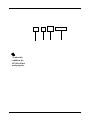
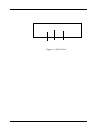
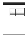
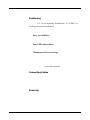
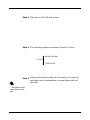
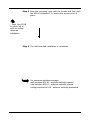
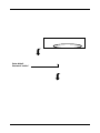
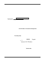
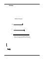
Wireless 11b Access Point AP11B
User’s Guide
Version 1.0
June 2003
FCC Radio Frequency Interference Statement
This equipment complies with FCC radiation exposure limits set forth for an uncontrolled environment. The antenna(s) used for this equipment must be installed to
provide a separation distance of at least eight inches (20cm) from all persons.
This equipment must not be operated in conjunction with any other antenna.
CE Warning
This is a Class B product. In a domestic environment, this product may cause radio
interference, in which case the user may be required to take adequate measures.
Copyright Notice
The material in this document is the intellectual property of MICRO-STAR
INTERNATIONAL. We take every care in the preparation of this document, but no
guarantee is given as to the correctness of its contents. Our products are under
continual improvement and we reserve the right to make changes without notice.
Trademarks
All trademarks used in this manual are the sole property of their respective owners.
Windows is a registered trademark of Microsoft Corporation.
Revision History
Revision
V 1.0
Revision History
First Release
Date
June 2003
Important Safety Precautions
Always read and follow these basic safety precautions carefully when handling any
piece of electronic component.
1.
2.
3.
4.
5.
6.
7.
8.
Keep this User’s Manual for future reference.
Keep this equipment away from humidity.
Lay this equipment on a reliable flat surface before setting it up.
The openings on the enclosure are for air convection hence protects the
equipment from overheating.
All cautions and warnings on the equipment should be noted.
Never pour any liquid into the opening that could damage or cause
electrical shock.
If any of the following situations arises, get the equipment checked by a
service personnel:
Liquid has penetrated into the equipment
The equipment has been exposed to moisture
The equipment has not work well or you can not get it work according to User’s Manual
The equipment has dropped and damaged
If the equipment has obvious sign of breakage
DO NOT LEAVE THIS EQUIPMENT IN AN ENVIRONMENT
UNCONDITIONED, STORAGE TEMPERATURE ABOVE 700 C OR BELOW
-300C, IT MAY DAMAGE THE EQUIPMENT.
Table of Contents
1. Introduction ................................................................................................... 1
1.1 What is AP11B .......................................................................................... 1
1.2 How AP11B Works .................................................................................... 2
1.3 Features & Benefits ................................................................................... 3
1.4 Package Contents ...................................................................................... 4
2. Unit Description ............................................................................................ 5
2.1 Front View ................................................................................................. 5
2.1.1 LEDs Display .......................................................................................... 6
2.2 Rear View ................................................................................................... 7
2.3 Side View ................................................................................................... 8
3. Installation/Configuration ............................................................................ 9
3.1 Default Parameters ..................................................................................... 9
3.2 System Requirements ................................................................................ 9
3.3 Installing Your AP11B ............................................................................... 10
3.3.1 Free-standing Installation ................................................................... 11
3.3.2 Wall- or Ceiling-mounted Installation .................................................. 13
3.4 Web-based Configuration ......................................................................... 15
3.4.1 Typical Configuration .......................................................................... 17
3.4.2 Customized Configuration ................................................................... 20
System ...................................................................................................... 21
LAN .......................................................................................................... 25
Wireless .................................................................................................... 26
4. Technical Support ......................................................................................... 30
5. Specifications ................................................................................................ 31
6. Glossary ........................................................................................................ 33
Index .................................................................................................................. 39
h 11Mbps Data Rate/150-500ft Indoor Range
h Superior Antennas Design
h Wi-Fi Certified
h Easy Installation
h WEP Security to Ensure Privacy
* Under this
condition, the
AP11B will not
work properly.
Wall- or Ceiling-mounted Installation.
Figure 3: Side Panel
Default Parameters
Password
IP address
Subnet mask
SSID
Channel
Encryption
DHCP client
h
h
admin
192.168.1.254
255.255.255.0
AP11B
7
Off
Disable
Positioning
3.3.1 Free-standing Installation, 3.3.2 Wall- or
Ceiling-mounted Installation
Easy accessibility:
Easy LEDs observation
Maximum wireless coverage
vertically upward
Connecting Cables
Power Up
Step 1 Take out the AP11B and its stand.
Step 2 Locate the mounting holes on the rear panel of the
AP11B and align them to the hooks of the stand.
Step 3 The AP11B is hooked to the stand.
The free-standing installation is completed.
Step 1 Take out the AP11B and screws.
Step 2 The mounting distance between screws is 5.5cm.
second screw
5.5cm
first screw
Step 3 Hammer the screws partly into the wall (or the ceiling)
and then use the screwdriver to screw them half into
the wall.*
* An electric drill
may also do the
job.
Step 4 Align the mounting holes with the screws and then push
the AP11B downward* to secure the access point in
place.
* Push the AP11B
to either left or
right for ceilingmounted
installation.
Step 5 The wall-mounted installation is completed.
For maximum wireless coverage:
wall-mounted AP11B - antenna vertically upward
free-standing AP11B - antenna vertically upward
ceiling-mounted AP11B - antenna vertically downward
192.168.1.254
Enter default
Password “admin”
The Menu Bar
Main Window of Customized Configuration
The Menu Bar
HOME
Logout
p. 11
System LAN Wireless
The Menu Bar
System
Password Setting
admin
Once you have
changed the settings
in each option, press
Apply to save the
changes, or Cancle
to abandon. Press
Help can bring up the
help window.
Firmware Upgrade
How to upgrade the firmware:
The Menu Bar
Main Window of Customized Configuration
The Menu Bar
HOME
Logout
p. 11
System LAN Wireless
The Menu Bar
System
Password Setting
admin
Once you have
changed the settings
in each option, press
Apply to save the
changes, or Cancle
to abandon. Press
Help can bring up the
help window.
Firmware Upgrade
How to upgrade the firmware:
Upgrade
Firmware
make sure the
file is correct
press here
OK
System Status
Select this
Restart
System Status
LAN
DHCP Client - default Disable
IP Address - default 192.168.1.254
Subnet Mask - default 255.255.255.0
Default Gateway - optional
Wireless
SSID & Channel
3-1
1
2
How to change the SSID and Channel:
Apply
System
Status
3-2
System
Radio Settings
* These settings are for
advanced users or MIS
staff only. If you do
not know how to set
these parameters, it is
recommended to use
the default value.
Encryption
Associated Client List
Association Control
http://www.msi.com.tw/
[email protected]
Data Rates
Standard
Range
Frequency
Wireless Radio Type
ModulationType
WEP Encryption
Antenna
Protocols Support
Wired Interface
User Selectable Settings
LED Indicators
Output Power
Sensitivity
Power Consumption
Power Adapter
Dimensions
Weight
Operating Environment
Input Voltage
Package Contents
Certifications
Accept Broadcast DDIS
Access Point
Association
Authentication Type
Beacon Period
Channel
Client Privileges
Default Gateway
DHCP Client
Dynamic Host Configuration Protocol
DNS Server Address
DSL Modem
DTIM Period
Delivery Traffic Indication Message
Ethernet
IP Address
Internet Protocol
ISP Gateway Address
ISP
Internet Service Provider
LAN
Local Area Network
MAC Address
NAT
Network Address Translation
Open System
PPPoE
Point-to-Point Protocol over Ethernet
Radio Preamble
Shared Key
SPI
Stateful Packet Inspection
SSID
Service Set Identifier
Subnet Mask
TCP/IP
Transmission Control Protocol/Internet Protocol
WAN
Wide Area Network
WEP
WEP Key
Index
A
Ad-hoc 2
Antenna 3, 5, 32
C
Channel
Default Channel 18
Setting the Channel 18
SSID & Channel 26
Customized configuration 16, 20
LAN 25
IP setting 25
System
Firmware upgrade 22
Password setting 21
Restart 24
System status 24
Wireless 26
Associated client list 29
Association control 29
Encryption 28
Radio setting 27
SSID & Channel 26
D
Data rates 32
Default gateway 25
DHCP client 25
E
Encryption type 19
Ethernet Link 6
External dipole antenna 5
F
Free-standing 10
Frequency 32
H
Hexadecimal digits 19
I
Infrastructure networking mode 2
Interface 32
IP address 15, 25
L
LAN 25
LEDs 5, 6
M
Modulation type 32
O
Open system 19
P
Password 15
Protocols 32
R
Range 32
RJ-45 Ethernet Jack 8
S
Sensitivity 32
Shared key 19
Subnet mask 25
T
Traffic utilization 6
Typical configuration 16, 17
1-2-3 Setup Wizard 17
Step 1: Setting the SSID 17
Step 2: Setting the Channel 18
Step 3: WEP Settings 18
W
Wall-mounted 10, 13
Web-based configuration 15
WEP Settings 18
Authentication Type 19
Data Encryption 18
Encryption Type 19
WEP Key 19
Wireless coverage 10
Wireless status 6
WLAN (Wireless Local Area Network) 17