1
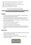
DAC
Distributed Adaptive Control:
Tutorial on Foraging
Paul Verschure & Armin Duff Eds.
2
Index
DAC Tutorial on Foraging
DAC5 Armin Duff, Encarni Marcos and Riccardo Zucca
Tutorial 1: Getting Started Armin Duff and Riccardo Zucca
Tutorial 2: DAC Reactive Layer Riccardo Zucca and Armin Duff
Tutorial 3: DAC Adaptive Layer Armin Duff and Riccardo Zucca
Tutorial 4: DAC Contextual Layer Encarni Marcos and Armin Duff
5
14
23
28
34
Appendix
DAC Simulation Environment: iqr and Gazebo Setup Armin Duff and Riccardo Zucca
iqr Basics Riccardo Zucca
3
41
48
DAC Tutorial on Foraging
DAC Tutorial on Foraging
4
DAC5
DAC5
DAC is based on the fundamental assumption that foraging can be explained
on the basis of the interaction of three layers of control: reactive, adaptive and
contextual. DAC5 was proposed as a model for classical and operant conditioning
(Pavlov, 1927; Thorndike, 1911; Verschure, 1998). The reactive layer provides a set of
reflexes allowing the system to interact with the environment—unconditioned stimuli
(US) to unconditioned response (UR). The adaptive layer is a model of classical
conditioning and fulfills a two-fold task. On the one hand it learns to associate the
conditioned stimuli (CS) to the UR, forming the conditioned response (CR). On the
other hand, it forms internal representations of the CS used by the contextual layer.
The contextual layer is a model for operant conditioning; it provides the system with
short- and long-term memory structures. The sensorimotor contingencies formed at
the level of the adaptive layer are acquired and retained in these memory structures,
forming behavioural sequences. The representations stored in the contextual layer
are constantly matched against the ongoing perceptions allowing for the retrieval
of successful behavioural sequences in similar contexts.
The prototypical robot test case for DAC5 is a foraging task in an open arena. In
this task, the robot, equipped with proximal and distal sensors, explores the arena in
search of light sources while avoiding collisions with the surrounding wall. Coloured
patches scattered on the floor serve as landmarks for the navigation. In the
framework of classical conditioning, the proximal (e.g. distance and light) sensors
serve as aversive and appetitive USs. Close to the light or at a collision a UR is
triggered such that the robot approaches the light or turns away from the wall. The
coloured patches serve as CSs.
Reactive and Adaptive Layer
In DAC5, the adaptive layer learns sensorimotor contingencies generated
by the reactive layer and forms internal representations of the environment
based on the classical conditioning paradigm (Pavlov, 1927). An unconditioned
stimulus US triggers an unconditioned response UR (see Fig. 1). A US event also
induces activity in populations of units which reflect an internal state (IS). Learning
consists of associating a conditioned stimulus CS to the US such that after learning,
the CS on its own can trigger a conditioned response CR (see Fig. 1). In doing so
it combines perceptual and behavioural learning. Behavioural learning associates
the different CSs to the correct CRs. Perceptual learning compresses the higher
dimensional CS to the lower dimensional CR.
5
DAC Tutorial on Foraging
CS
y
W
x
CR
Adaptive
IS
e
U
V
r
Light
sensors
Camera
Figure 1.
UR
a
Reactive
US
Motors
Somatic
AS
s
U
The Adaptive and the Reactive layer: squared boxes stand for neuronal
groups, arrows stand for static (solid line), and adaptive (dashed line) synaptic
transitions between the groups.
We define the following abbreviations for the activities in the different cell groups:
a
Usually the dimensionality N of the CS is higher than the dimensionality K of the IS.
The dimensionality M of the US is in general but not necessarily similar or equal to
the dimensionality K of the IS cell group. In the general case the activity of the US and
the CS cell can be a nonlinear function of the sensor readings. Usually, however, the
function is the identity function. With these definitions the forward dynamics of the
adaptive and reactive layer can be written as:
6
DAC5
The US cell group can be comprised of neurons for different values of USs such as
appetitive and aversive stimuli. To simplify the notation they are all represented in the
vector s. The predefined weight matrix V determines what actions are triggered by the
different states of US. It connects the elements of US to specific elements of IS and
thus via the action selection AS sets specific actions. W describes the association of
CS to IS and is subject to learning. The slow dynamics describing the change of the weights W follow the learning rule
called correlative subspace learning (CSL) (Duff et al., 2011):
The parameter η is the learning rate and may vary with time. Learning is driven by the
two product terms
and
. The parameter varies between -1 and 1
and balances the influence of the two terms
and
on learning. With a of -1
only
drives learning and for a of 1 the learning dynamics are determined by
only. The term
is related to the auto-correlation of the CS. With the assumption
that the learning rate is small and the mean of x over time is zero, we can regard
as the instantaneous estimate of the real auto-correlation. Thus, we can identify
this term with perceptual learning as it depends only on the CS. The term
relates
to the correlation of the CS and the UR. Again it can be seen as the instantaneous
estimate of the real correlation. We identify this term with behavioural learning as it
contributes to learning the association between the CS and the UR. However, with
only these two terms the weights would grow exponentially and never converge. The
negative normalisation term -W y depresses the weights and assures convergence.
The parameter allows to control the influence of the terms
and
on
learning, and thus allows to balance perceptual and behavioural learning. With a of
-1 learning is only driven by the CS and the learning rule corresponds to the subspace
learning algorithm proposed by Oja. A of -1 corresponds to purely perceptual
learning.
The perceptual representations defined by the extracted subspace are the so-called
prototypes defined as
. The prototypes are the basic elements used
to store and recall action sequences in the long-term memory of the contextual
layer (Verschure, 2003; Verschure, 2003a). The prototype corresponds to the linear
projection of x to the learned subspace defined by the weight matrix W. Thus the
prototypes directly depend on the extracted subspace and the parameter allows
to control if the prototypes are defined more by the auto-correlation of the CSs or
by the correlation between the CS and the UR. What is the optimal balance between
perceptual and behavioural learning, i.e. what is the optimal value for is not clear in
advance and will strongly depend on the task at hand and the statistics of the CS and
7
DAC Tutorial on Foraging
the UR. In this way, the adaptive layer fulfills its twofold task of learning the sensory
motor associations and forming internal representations, i.e. the prototypes e for the
planning system of the contextual layer.
Contextual Layer
The contextual layer provides mechanisms for memorising and recalling behavioural
sequences. It comprises two memory structures: a short-term memory (STM), and a
long-term memory (LTM) for the permanent storage of information (see Fig. 2 below).
These allow the system to acquire, retain and express sequences of the sensorimotor
contingencies the adaptive layer generates. The acquisition of information into
memory is done in two steps:
1. Sensorimotor events generated by the adaptive layer are stored in the STM, forming a behavioural sequence.
2.
When a goal state is reached the sequence of sensorimotor events stored
in the STM are copied into the LTM and the STM is initialised.
The information stored in the LTM is then recalled to reach goal states, as follows:
1.
Whenever a new sensory event is generated it is compared with all the
ones stored in the LTM.
2.
The segments of the LTM that are similar enough (similarity defined by
a matching criteria) to the generated one are retrieved.
3.
Retrieved segments from memory contribute to compute the selected
action.
4.
The selection of segments from the LTM is biased by previous experience
to achieve sequential chaining
8
DAC5
Figure 2. Contextual layer: (1) The generated CS prototype e from the adaptive
layer and the executed action a are stored as a behavioural couplet in the
STM. (2) When a goal state is achieved the information stored in the STM
is copied into the LTM as a sequence and the STM is initialised. (3) The
generated CS prototype e is compared with all the prototypes e stored in
the LTM. (4) The action a proposed by the contextual layer is calculated as a
weighted sum over the actions associated with the sensory events selected
from the LTM.
a1
aNS
e7 a7
a6
a2
a5
e6
STM
a3 e3
a4
e4
LTM
2
e12 a12
e13 a13
e21 a21
e22 a22
e23 a23
e2NS a2NS
eN 1 aN 1
eN 2 aN 2
eN 3 aN 3
eN NS aN NS
L
1
4
3
e15
L
L
L
L
L
L
L
1
IS
e
CS
e11 a11
e1NS a1NS
Contextual control
eNS
e2
y
W
x
CR
Adaptive
e1
U
Camera
s
r
V
Light
sensors
UR
a
Reactive
US
Motors
Somatic
AS
U
The STM is the structure that temporarily stores the behavioural sequence that is
being experienced by the robot and that did not lead to a goal state yet. It is a ring
buffer formed by a sequence of NS segments. Each segment contains the action
executed a by the robot together with the CS prototype e that was generated at
that time. When a goal state is reached the content of the STM is copied into the
LTM and the STM is initialised. The LTM contains NL sequences of maximum size
9
DAC Tutorial on Foraging
of NS segments. Each sequence stored in the LTM has a value that relates to the goal
states they lead to (e. g. +1 for an aversive state such as collision, +1 for an appetitive
state such as reward).
The retrieval of the proper action from memory is based on the similarity between the
current CS prototype e and the CS prototypes elq previously stored in the LTM. This
similarity is calculated using a distance measurement as follows:
The degree of matching of segment l in sequence q determines the input to its socalled collector:
The collector determines the contribution of the segment to the final proposed
action by the contextual layer. Its activity depends on the distance d(.) between the
current generated CS e prototype and the CS elq prototype stored in segment l and
sequence q and on a so-called trigger value t that is associated with each
segment lq in memory. The trigger value is used to ensure chaining through a sequence. Its value depends on
whether the segment that temporarily precedes it in a sequence was selected in the
previous cycle. If it was not selected the trigger has a default value of 1 and therefore it
does not bias the selection of the segment. However if segment l-1 in sequence q was
selected then the trigger value of segment l in sequence q is set to a higher value than
1. This means that the collector unit associated with that segment will increase its
value and that therefore the segment will have more probability of being selected in
future decision-making. The trigger value decreases asymptotically as:
where
. When a segment is selected its trigger value is reset to 1.
The action proposed by the contextual layer is calculated using the activity of the
collectors, but only if these collectors satisfy two criteria: (1) Its activity is above
a predefined threshold (
); and (2) Its activity is inside a predefined percentage
range from the maximum collector’s activity, e. g. the collectors compete in an
E%-Max Winner Take All (WTA) mechanism (Almeida et al., 2009) in which only the
10
DAC5
collectors inside with an activation equal or greater than E% from the maximum
collector’s activity contribute to the action. These two criteria can be dynamically
adjusted so that they change their value according to the certainty or uncertainty of
the robot, e. g. when the robot is still learning it will have a low value of
and E% so
that it can take into account a greater number of proposals. The selected collectors
contribute to the contextual action as:
where
is the distance measured as the number of segments needed to reach
the goal state from the current state, i. e. distance between selected segment and
the last segment in the sequence. The plus sign means that the selected segment
corresponds to an appetitive goal state sequence whereas the minus sign means
that it belongs to an aversive goal state sequence. Only if the computed action is
positive it is executed. In this way, backwards actions are avoided.
The activation of the contextual layer depends on the quality of the generated
prototypes CS e from the adaptive layer. This quality is assessed by using a
discrepancy measure that runs an average distance between the predicted prototypes CS e and the actual CS x value:
where
defines the integration time constant and the distance d(x,e) between
actual CS x and estimated CS e prototypes. Only when this discrepancy measure
falls bellow a certain threshold (confidence threshold) the contextual layer is enabled.
An action selection mechanism receives three actions, one from each layer of the
architecture: reactive action ( ), adaptive action ( ) and contextual action ( ).
The final action executed by the robot is selected through a priority mechanism in
which the most priority action is the reactive action, then the contextual action, and
finally the adaptive action.
11
DAC Tutorial on Foraging
References
de Almeida, L., Idiart, M. & Lisman, J. E. (2009) A Second Function of GammaFrequency Oscillations: An E%-Max Winner-Take-All Mechanism Selects which Cells
Fire. Journal of Neuroscience 29 (23). p.7497-7503.
Duff, A., Sanchez-Fibla, M. & Verschure, P. F. M. J. (2011) A biologically based model
for the integration of sensory-motor contingencies in rules and plans: A prefrontal
cortex based extension of the Distributed Adaptive Control architecture. Brain
Research Bulletin 85 (5). p.289-304.
Oja, E., Ogawa, H. & Wangviwattana, J. (1992) Principal component analysis
by homogeneous neural networks, Part I: The weighted subspace criterion. IEICE
Trans Inf Syst 75. p.366-375 Pavlov, I. P. (1927) Conditioned Reflexes: An Investigation of the Physiological Activity of
the Cerebral Cortex.
Thorndike, E. (1911) Animal Intelligence. Verschure, P. F. M. .J. (1998) Synthetic epistemology: The acquisition, retention,
and expression of knowledge in natural and synthetic systems. In: Proceedings
of IEEE World Conference on Computational Intelligence, Anchorage, Alaska. p.147-152. Verschure, P.F.M.J., Voegtlin, T. & Douglas, R.J. (2003a) Environmentally mediated
synergy between perception and behaviour in mobile robots. Nature 425
(6958). p.620-624.
Verschure, P.F.M.J. & Althaus, P. (2003) A real-world rational agent: Unifying old and
new. AI. Cogn Sci 27. p.561-590.
12
DAC5
13
DAC Tutorial on Foraging
Tutorial 1: Getting Started
Foraging
Foraging, i.e. the capability of an animal to search and find food, critically determines
its evolutionary fitness as it plays an important role in its ability to survive and
reproduce. In behavioural terminology, foraging represents a goal-oriented
exploration for resources normally motivated by food deprivation. Foraging is
an advanced, goal-oriented behaviour where prior knowledge of an environment
and acquired behavioural strategies must be matched to the novelty and hazards
presented by an unpredictable world and the varying allostatic requirements of the
behaving system itself, e.g. energetic and reproductive needs. These constraints
are defined at varying spatial and temporal scales, where a successful forager
must simultaneously satisfy local and global constraints, such as performing
obstacle avoidance while staying on course to reach a known feeding site whilst
also allocating resources consistent with its allostatic needs. As such, foraging
represents an excellent test case for an autonomous control system.
Figure 1. Simulated agent (red cylinder with the grey dot on top) and environment for
the resticted arena foraging task. 14
Tutorial 1: Getting Started
In the following tutorials we explore how the different layers of DAC5 contributes
to solving a foraging task. In particular, we test DAC5 in a restricted arena foraging
task (see Fig. 1). The squared arena contains coloured patches and a light source
visible by the downward-pointing camera of the robot. The light intensity decays
with the distance and it is only detectable for the light sensors of the robot at a
limited distance. The robot is placed in one of the three starting positions (grey
circles) facing the patches, and the goal of the robot is to reach the light. Every time
the robot collides with the wall a new trial starts and randomly repositions the robot
at one of the three start positions. This task can be described in terms of classical
conditioning: the light serves as US where the patches serve as CSs. As in this
configuration of the task, all of the top patches have the same colour and the task is
ambiguous and cannot be solved without the context given by the bottom patches.
Thus, to solve the task it is essential for the robot to form adequate internal
representations of the bottom patches. Only stable and reliable prototypes will allow
the memory structures of the contextual layer to store and later recall the correct
actions for the ambiguous cues.
The restricted open arena foraging task isolates a core situation of an open arena
foraging task in limiting the agent to specific start positions. For an agent endowed
only with egocentric inputs, cues in an open arena foraging task are ambiguous
and the correct action can only be determined when taking into account the current
context (see Fig. 2A). If the agent comes from the left side (solid line) it has to
turn left at the red patch. If it comes from the right side it has to turn right. Thus,
the red cue is ambiguous but can be disambiguated by the patches the agent
encounters before the red patch. Figure 2B is the very same situation in a different
configuration. When restricted to the three start positions defined in figure, the agent
encounters the same stimuli as in Figure 2A; this is the configuration we use to test
the contextual layer. For the adaptive layer this configuration is not solvable since
the adaptive layer does not have any contextual information. To be able to test the
adaptive layer the red patches were disambiguated by changing the colours (Fig.
2C). In this configuration the three upper patches serve as cue patches and the three
lower patches lose their role and become distractor patches. The restricted open
arena foraging task in this special configuration is designed to assess the two-fold
task of the adaptive layer systematically. For behavioural learning, the patches
that can be associated to a US should elicit the corresponding action (CR). For the
perceptual learning all the different patches, cue and distractor patches, should be
represented in the IS, but only lead to an action if they are associated to a US. For the
distractor patches, the IS activity should remain sub-threshold.
15
DAC Tutorial on Foraging
A.
B.
C.
Figure 2. Patch configuration: A. General situation in an open arena foraging
task. B. Equivalent constellation of patches as in A in the restricted open
arena foraging task. C. Disambiguation of the patches for testing the
adaptive layer that is not context aware.
In this tutorial you will get aquainted with the iqr (Bernardet & Verschure, 2010) and
the Gazebo simulation environment (Koenig et al., 2004), and learn how to control
the robot. In the remaining tutorials you will analyse the behaviour of the different
layers and how they have to be tuned in order to solve the restricted open arena
foraging tasks.
Tutorial
Start iqr and Gazebo
Gazebo and iqr work as a server-client application running on two separate
processes.
In a new terminal window (Ctrl+Alt+t to open it) start an instance of Gazebo and load
the world template that will be used throughout the entire tutorial, by typing:
cd $HOME/iqr-gazebo/DAC_files
gazebo DAC_basic_arena.world
Gazebo GUI will open with a configuration similar to the one illustrated in Figure 3.
During this tutorial and the following ones you will not need to modify any aspect of
the simulated world, nevertheless, interested readers can find the reference manual
of Gazebo at the project website (http://www.gazebosim.org).
16
Tutorial 1: Getting Started
Figure 3.
Gazebo GUI with a fly-view of the foraging task arena.
Open a second terminal window, start iqr and open the DACReactiveBug_ex system
by typing the following command:
cd $HOME/iqr-gazebo/DAC_files
iqr -f DACReactiveBug_ex.iqr
The iqr GUI will open and the DacReactiveBug controller will be in place as
illustrated in Figure 4. The system is not complete and during this tutorial you will
be required to figure out how to build the final system. A final version of the file
(DacReactiveBug.iqr) with the complete solution to the system is also provided in
the same folder.
Bug: is the built-in module that interfaces iqr with Gazebo. The small rounded icon
at the bottom right part of the Bug icon indicates that this process is interfacing with
an external module. All the necessary connections to interface iqr and Gazebo are
already made for you, but if interested you can have a look at the properties of the
process by right-clicking the Bug process icon, and selecting Properties from the
contextual menu.
Reactive layer: is the process where the mapping between the sensory stimuli and
the pre-wired unconditioned responses takes place.
Selection: is the process in charge of selecting the action to be executed. The output
of this process is a motor command that is mapped to the actuators of the robot.
17
DAC Tutorial on Foraging
Figure 4. iqr GUI and the DACReactiveBug system as it appears in the diagram pane.
You can inspect each process by clicking on the corresponding tab in the tab bar,
while to change the process parameters you can double-click on the process icon
or use the contextual menu to open the Properties dialogue (right-click->Properties).
For this tutorial you don’t have to worry about changing any of the processes’
properties since all of the necessary connections were already made for you.
Now, move to the Bug diagram pane. You should see something like this:
Figure 5.
The Bug process.
The Bug process (Fig. 5) is made by an assembly of 15 different groups of neurons
that can receive inputs or send outputs from/to the Gazebo robot. The robot
18
Tutorial 1: Getting Started
comes equipped with different sensors (camera, proximity sensors, light sensors,
microphone, GPS, gripper sensor) and effectors (motor, gripper and a speaker),
but to implement the reactive layer of DAC we will only need two of them: the light
sensors that input to the Light group of the Bug process, and the motor joints that
execute the commands received from the Motor group of the process.
To get started and gain some confidence with the robot and all of its features, we
will start exploring the robot sensors and effectors. For more details about the other
available sensors we point the user to read the iqr-gazebo wiki (https://code.google.
com/p/iqr-gazebo/wiki/iqrBugFeatures).
The motors: The motors of the robot are controlled via the 9x9 neurons Motor
group (see Fig. 6) of the Bug process. The movement of the robot is computed
from the position of the cell with the highest activity in the Motor group lattice. The
Y axis represents the force applied to each joint to move the robot while the X axis
represents the Rotation applied to it.
Figure 6. Schematic representation of the Motor group mapping. The black dot
represents the stationary condition where no force and rotation are
applied to the robot wheels.
Light sensors: the robot is equipped with 32 light sensors equally spaced on the
robot body that are mapped into the Light group of the Bug process.
Camera sensor: a colour camera placed in the frontal part of the robot and facing
downwards receives information from the environment. The input of the camera
is then split into three channels (RGB is the default) and transmitted to the three
colour channel groups in the Bug process. The resolution of the camera and its input
modality can be changed in the Properties dialogue (right-click and select Properties
from the contextual menu).
19
DAC Tutorial on Foraging
Exercise 1: Moving the Robot Forward
Start the simulation by pressing the Run button. Move to the Bug process diagram
pane and open the State Manipulation panel of the Motor group (right-click the
group icon and select State Manipulation Panel from the contextual menu). The
State Manipulation panel is a tool that is used to directly change the activity of
single neurons in the groups.
To move the robot forward left-click the fifth cell of the first row in the motor lattice
grid (see Fig. 7). Set it to a value of 1 and click on Add. The command will then be
added on a list in the right pane.
Figure 7. State Manipulation panel configuration to move the robot forward.
Now you can click Send to execute the command. The robot will start moving in
the forward direction.
To stop executing the command click on the Revoke button.
20
Tutorial 1: Getting Started
Q1. Which cell do you need to activate to make the robot turn to its left?
and to its right?
Q2. Which cell do you need to activate to make the robot move backwards?
Q2. How do you control the speed of the robot?
Exercise 2: Make the Robot Move Autonomously
Using the State Manipulation panel is not the most effective way to control your robot.
We want the robot to behave autonomously in its environment.
Stop your simulation and close the State Manipulation panel. Move to the Selection
process diagram pane (see Fig. 8).
Figure 8.
The action selection process.
The action selection process: this process is made up of six different groups that
define the default robot behaviour (i.e. Explore the environment) and a pre-wired
reflexive behaviour (i.e. Approach).
The most basic behaviour of the robot is to explore its environment on a straight direction.
To make the robot move autonomously along a straight path we will have to
constantly activate the exploratory behaviour of the robot. This stereotyped behaviour
can be achieved by feeding the Explore group with a constant input:
21
DAC Tutorial on Foraging
Create an excitatory connection from the Const Speed to the Explore group.
Click on the red Add Connection button in the Diagram edit toolbar and then click
on the Const Speed group. Now click on one of the yellow squares at the edge of
the Explore group to connect the two groups. The Const Speed group is made up of
a single cell that is always active and represents the constant driving force for the
exploratory behaviour.
Now let’s try to make the robot move on its own.
Q1. The Motor In group is an interface to the Motor group of the Bug process.
How do you have to connect the Explore group to the Motor In group to make
the robot move forward? Connect the two groups then run the simulation to
observe if the robot behaves as expected.
Before we continue with the implementation of the Reactive layer, try to observe how
the different sensors of the robot react to the environment. Move to the Bug process
diagram pane and open the Space plot of the Red/Hue group (right-click the group
icon and select Space Plot from the contextual menu). The Space Plot is a useful
tool that plots the instantaneous activation of the group cells in a two-dimensional
space. In this case what the plot shows is the input received by the camera of the
robot while exploring the arena.
Try by yourself and inspect through the respective Space plots the behaviour of the
light sensors and the proximity sensors.
Q2. How do the light sensors behave?
You can now save your system (press Ctrl+s or select Save from the File menu) and
go on with the second tutorial.
References
Bernardet, U. & Verschure, P.F.M.J. (2010) iqr: A Tool for the Construction of Multilevel Simulations of Brain and Behaviour. Neuroinformatics 8 (2). p.113-134. Koenig, N. & Howard, A. (2004) Design and use paradigms for Gazebo, an opensource multi-robot simulator. In: Proceedings of IEEE/RSJ International Conference
on Intelligent Robots and Systems. p.2149-2154.
22
Tutorial 2: DAC Reactive Layer
Tutorial 2: DAC Reactive Layer
In the previous tutorial we built a first system that allowed the robot to explore
its environment in a very primitive way. The next step, now, is to make the robot
responsive to its environment and behave accordingly.
For a behaving system the basic competence for it to be able to interact in an
effective way with its environment is derived from a a reactive control structure.
By solely relying on a set of pre-wired relationships between US events and URs, the
agent will reflexively react to immediate events in the environment.
The triggering stimuli, USs, are derived from the proximal sensors (i.e. light sensors
of the robot) and the URs are mapped into motor actions.
Nevertheless, as we will see in the next tutorial, the activation of any reflex will also
provide cues for learning that are used by the DAC adaptive layer.
Exercise 1: The Reactive Layer Implemented—Reflexively Approach a
Source of Light
If not already opened, start iqr and Gazebo using the same commands as in Tutorial 1.
The DAC Reactive layer is implemented in iqr in the Reactive layer process (see Fig. 1)
which you can access by clicking the Reactive layer tab in the tab bar. Figure 1.
The Reactive layer implemented in the iqr system.
23
DAC Tutorial on Foraging
As depicted in Figure 2, the Reactive layer is composed of two different groups of linear
threshold neurons:
The US group, which receives a compressed version of the light sensors
and constitutes the input to the second group.
The Approach group, which defines the mapping to the reflexive behaviours.
Information from the latter is then passed to the Action Selection process to trigger the
unconditioned response (i.e. the appropriate sequence of motor commands).
Figure 2. US and Approach groups: The US group is a 7x1 group of cells that
receives a compressed version of the light sensor’s input. Abbreviations for
the US group: LS, left frontal sensor; FS, frontal sensor; and RS, right frontal
sensor. The Approach group is a 9x1 group of cells that defines the repertoire
of pre-wired behaviours. Abbreviations for the Approach group: L, turn left; F, go
forward, and R, turn right.
In order for the robot to directly approach the light source when it is sensed by one of its
sensors, we need to create a correct mapping between the sensors and the effectors.
Q1. Try to figure out how to map the US group to trigger the correct reflexes in the
Approach group in order for the robot to approach the light source once it is
detected.
To set the connectivity pattern, open the Connection properties dialogue (right-click
on the connection between US and Approach groups and select Properties from the
contextual menu). Set the Pattern type to PatternTuples from the set type drop-down
menu (see Fig. 3, left side of the panel). This kind of pattern is used to define individual
cell-to-cell projections between groups. Click Apply to confirm and then click the Edit
button near the PatternTuples label. Your dialogue should now look similar to the one
illustrated in Figure 3.
24
Tutorial 2: DAC Reactive Layer
Figure 3. Connection Properties dialogue.
Q2. Implement the connectivity pattern that you defined in the previous step. To
set a connection select a cell in the Source group and the corresponding target
cell in the Target group. Next click Add to accept the tuple. To define a new
tuple, you first have to click the Clear button and then you can repeat the same
operations as in the previous step. Once you are done click Apply and Close.
Remember to save your system whenever you make changes.
Q3. Do you expect that the system will work properly? If not, try to explain why?
Q4. Run the simulation and check if your response was correct. (You can find the
correct solution to the connectivity pattern in the file DacReactiveBug.iqr).
Exercise 2: The Reactive Layer Implemented—Actions Selection and
Conflict Resolution
For the robot to properly behave through a purely reactive system one more step is
missing. We defined the reactive controller by mapping the occurrence of a US onto a
specific action of the robot, approach in our case. Nevertheless this was not sufficient for
the robot to correctly approach the light since the ‘go forward’ behaviour took priority. We
thus need a mechanism to resolve the conflicts between different concurrent actions.
25
DAC Tutorial on Foraging
To implement this mechanism, open the Selection process diagram pane. To
prioritise the approaching behaviour over the exploratory one, the latter mechanism
needs to be shut down so that the unconditioned response can be expressed.
Q5. Try to figure out what is the most plausible way to inhibit the expression of the
exploratory behaviour and make the robot reach the light source.
Q6. Make the necessary changes to your model and run the simulation. (You can
find the one-step solution in the file DacReactiveBug.iqr).
Stop the simulation. Move to the Reactive layer diagram pane and open the
Properties dialogue of the Approach group. Click on the Edit button of the Neuron
type panel. Click the Membrane tab and change the Threshold value to a lower value
(e.g. 0.3). Run the simulation.
Q7. How does this change affect the behaviour of your robot?
Exercise 3: Recording and Plotting Data
iqr includes the Data Sampler tool (Fig. 4) which allows you to save the internal
states of all or part of the elements of the model. In what follows we will record and
plot the trajectories of the robot while performing the navigation task.
Open the Data Sampler (form the Data menu select Data Sampler) to record
the robot position coordinates from the GPS group of the Bug process.
Figure 4.
Data Sampler dialogue.
26
Tutorial 2: DAC Reactive Layer
Click the Bug tab in the tab bar and open the Space plot of the GPS group (rightclick on the group icon and select the State Plot). Drag the small icon highlighted in
Figure 5 and drop it to the Data Sampler window. Alternatively you can drag the GPS
group from the browser GUI to the Data Sampler dialogue.
Figure 5. GPS Space Plot: to copy the output of the GPS group to the Data Sampler drag the icon in the red circle to the Data Sampler dialogue.
In the Data Sampler dialogue choose the destination folder and file where to save
your data.
Select auto start/stop to automatically record the GPS coordinates when the
simulation starts.
(Optional) If you have Matlab or Octave installed on the computer you can
try to generate a trajectory plot like the one in Figure 6. The Matlab script
(plotTrajectory.m) is located in the DAC Files folder.
Figure 6.
Trajectories plot.
27
DAC Tutorial on Foraging
Tutorial 3: DAC Adaptive Layer
The Adaptive layer is a model for classical conditioning in that it learns
the association between CS and US. In doing so it does not only associate
the unconditioned responses to different CSs but it also generates internal
representations of the world, i.e. the prototypes. In this step of the tutorial we will
explore both the perceptual and behavioural learning aspects of the Adaptive layer.
To get started please open two terminals. In the first one we run the Gazebo
simulation environment by typing:
cd $HOME/iqr-gazebo/DAC_files
gazebo DAC_basic_arena.world
In the second terminal we run iqr by typing:
cd $HOME/iqr-gazebo/DAC_files
iqr -f DACBugBasicArena.iqr
In iqr the Adaptive layer is implemented as a module called Adaptive layer. As such
it defines all the necessary input and output cell groups including: CS, CR, UR but
also a cell group for the discrepancy and an additional cell group to display the
current weights of the Adaptive layer. If you open the Adaptive layer process tab
you can see how the different cell groups are integrated within the DAC system (Fig.
1). The UR cell group receives its input from the Reactive layer process. The CS cell
group receives its input from the colour vision module. The outputs of the Adaptive
layer module are the CR and the discrepancy. The display cell group serves as a
space plot of the connection weights. 28
Tutorial 3: DAC Adaptive Layer
Figure 1. The Adaptive layer process.
The parameters of the Adaptive layer can be changed in the Properties dialogue
of the Adaptive process (Fig. 2). You can access it by double-clicking the Adaptive
process icon in the Gazebo system diagram pane or through the browser GUI. Once
the dialogue is opened, press the Edit button. The main parameters are the learning
rate η which determines the learning speed, and the balance ζ which changes the
balance between perceptual and behavioural learning. The parameter ρ determines
the error correction term that we will not be changing in this tutorial. The weights W of the Adaptive layer are initialised randomly at the start of each simulation.
So learning starts anew every time you stop and start the simulation. To avoid
initialising the weights, you can pause the stimulation instead of stopping it. The
weights can also be saved and loaded from an external source. Click on the Read
Write tab, choose a file and tick the read or write box if you want to load or save the
weight matrix respectively.
Figure 2. Properties of the Adaptive layer module. In the first part of the tutorial we connected the sensors and motors in such a
way that the robot approaches the target light source based on the unconditioned
responses (UR) only. Now we want to see how the Adaptive layer can learn the
association between the patches on the floor and the target. To better analyse
the actions learned by the Adaptive layer we have suppressed the actions of the
Reactive layer by increasing the threshold of the reactive actions. The input to the
Adaptive layer is however still the pre threshold activity of the reactive actions so
that the Adaptive layer can learn the associations between the patches and the
activity of the light sensors. You can examine this change in the Reactive layer
process tab (Fig. 3).
29
DAC Tutorial on Foraging
Figure 3. The Reactive layer.
Exercise 1: Reactive vs. Adaptive
First we want to compare the Reactive vs. the Adaptive layer. To do so open the
Properties dialogue of the Adaptive process and set the learning rate η to zero. With
a learning rate of zero the weights W of the Adaptive layer will not change and thus
the Adaptive layer will not perform any actions. As we suppress the actions of the
reactive layer the robot should go straight on all of the positions.
Now increase the learning rate η to 0.001. After a few trials the robot should start
to approach the light source target. You can repeat the simulation with different
learning rates. The higher the learning rate the faster the learning, i.e. after fewer
trials the robot will turn towards the target. However, keep in mind that too high
learning rates often lead to instability both in the weights as well as in the behaviour.
Try to experiment with different learning rates. Q1: At what learning rate does the Adaptive layer learn the association within
just one trial?
In a next step we want to examine the weights matrix W and how the weights change
over time. To do so we can open a Space plot of the Display group. The Display space
plot shows the weight matrix W along the action space, i.e. the first rectangle of the
size of the CS cell group represents the weight connecting the CS cell group to the
first cell of the CR cell group and so one. Please restart the simulation and observe
how the weights evolve. Three regions of weights should stand out. 30
Tutorial 3: DAC Adaptive Layer
Q2: What regions do stand out? Why this regions? What do they represent?
The learning of these three regions is mostly driven by behavioural learning and
are learned first. If you continue the simulation you can observe how over time
other parts of the weight matrix are filled in. This is mostly driven by perceptual
learning; you can change the learning rate and observe how the speed of the
weights vary with the size of the learning rate.
In order to examine the perceptual learning of Adaptive learning we can first look
at the discrepancy D. The discrepancy measures the difference between the
conditional stimulus x and the prototype p, i.e. the difference between the perception
and the predicted perception. You can visualise the discrepancy by opening a Time
plot of the Discrepancy group (right-click the group icon and select Time Plot from
the contextual menu). Q3: For the three different learning rates 0.1, 0.01 and 0.001 how long does it
take for the discrepancy to fall bellow 0.1?
Exercise 2: Prototypes
The difference in the weight matrix distinguishing behavioural and perceptual
learning should also be reflected in the prototypes. You can examine this distinction
by opening the space plots of the CS and prototype cell groups. It might be
convenient if you elongate the size of the space plot so the the cells become
squared (just drag the lower right corner of the plot window). When you start the
simulation you can see how, at the beginning, the prototype hardly corresponds
to the CS. However, over time the prototype will resemble the CS more and more.
First the CSs that are associated to the UR will be represented in the prototypes.
Also over time, the patches that are not associated to an action will be represented
in the prototypes. These are however represented with a lower amplitude than the
patches associated to actions. You can visualise this difference by opening a time
plot of the prototype. You can clearly distinguish two consecutive peaks in the time
plot. The first is lower and belongs to a patch that is not associated with an action.
The second is higher and belongs to a patch that is associated to an action (Fig.
4). This difference can be seen as a bias of the internal representations towards
behaviourally relevant stimuli. 31
DAC Tutorial on Foraging
Figure 4.
Time plot of the prototype's amplitudes. The low peak corresponds to a
patch that is not associated to an action.
Q4: Compare the peaks in the time plot, and estimate the relative amplitude of
the peaks. The difference between the amplitude of the prototype of patches associated to
an action and patches not associated to a particular action is mainly influenced by
the balance between behavioural and perceptual learning. In the Adaptive layer this
balance is set through the balance parameter ζ.
Q5: Change the balance parameter to values lower than 0.98. How do the relative
amplitude of the peaks in the time plot change?
You might notice that after a short while the patches not associated with a reactive
action will trigger an action anyway. This happens as the perceptual learning drives
the weights, and thus the CR, over the threshold potential. You can eliminate this
actions by increasing the threshold of the CR threshold cell group. This, however, is
only possible within a certain range as high thresholds will impede the CR to trigger
any action. Exercise 3: Dealing with an Ambiguous Task
Finally, we will go back to the ambiguous arena. Close both Gazebo and iqr and
reopen both by typing the following commands in two different terminals:
32
Tutorial 3: DAC Adaptive Layer
cd $HOME/iqr-gazebo/DAC_files
gazebo DAC_basic_ambiguous_arena.world
In the second terminal we run the same iqr system as before by again typing:
cd $HOME/iqr-gazebo/DAC_files
iqr -f DACBugBasicArena.iqr
Figure 5. The ambiguous arena from a sideview.
In order for the Contextual layer to be able to learn this task, the Adaptive layer
has to provide the Contextual layer successful trails for the different cue patches.
The rationale is that through constant fast adaptation the contextual layer will, by
chance (i.e. when the robot starts several consecutive times in the same position),
learn the correct response. Start the simulation and observe the behaviour of the
robot. Q6: How is the chance of the robot going towards the target related to the
learning rate?
(Optional):
Q7: Use the Matlab script plotTrajectory.m to generate a plot of the trajectories of
the robot. To do so you need to log the GPS cell group using the iqr data logger
as in Tutorial 2. 33
DAC Tutorial on Foraging
Tutorial 4: DAC Contextual Layer
To analyse the behaviour of the contextual layer we will first test it with the DAC
basic restricted arena and then we will use the DAC basic ambiguous restricted
arena. In the first case the contextual layer is not fundamental to solve the task (as
you have already seen in section ‘Tutorial 3: Adaptive Layer’—the adaptive layer can
successfully learn the association between patches and actions since there is no
ambiguity between them), but it is helpful to understand the principles underlying this
layer. In the second case, the contextual layer is essential for the robot to sucessfully
reach the light because context is needed to disambiguate between the last patches
and therefore to perform the correct action. To investigate the first example we need
to open two terminals. In the first one we will run the gazebo environment:
cd $HOME/iqr-gazebo/DAC_files
gazebo DAC_basic_arena.world
And in the second terminal we will run the iqr system:
cd $HOME/iqr-gazebo/DAC_files
iqr -f DACBugBasicArena.iqr
In the file DACBugBasicArena.iqr you will find the complete DAC architecture (Fig.
1). It has a Bug module that has all the interfaces with the robot (sensors, motors,
etc.), a vision module that pre-processes the input from the robot’s camera, a
selection module that performs action selection from the actions proposed by
each layer of the architecture, and the three modules of the layers from the DAC
architecture: the reactive, the adaptive and the contextual layer.
Figure 1. Overall view of the DAC architecture and the Gazebot robot in iqr.
34
Tutorial 4: DAC Contextual Layer
The contextual layer module implements the mechanisms for storing and recalling
information from memory, as explained in the chapter on DAC5. It has seven
parameters that can be set by the user (Fig. 2):
height: number of sequences (NL) that can be stored in the LTM.
width: maximum number of segments (NS) that can form a sequence in
the STM and in the LTM.
discrepancy threshold: this parameter determines when the contextual layer
will be activated, i. e. when the distance between the current CS prototype
generated by the adaptive layer and the currentcs is below the discrepancy
threshold, the contextual layer is enabled.
selection threshold: only the collectors that have an activity above this selection threshold are selected and compete in an E%-WTA.
%-WTA: the percentage value that defines the WTA competition, i.e. only if
the activity of the collector is equal or greater than the %-WTA of the maximum
collector’s activity it is selected. Higher value of %-WTA means that less
collectors are selected and vice versa.
trigger reset: value that the trigger of a segment following a selected one gets
so that it has more probability of being selected later on.
trigger decay: defines how rapidly the trigger value decays back to its default
value of 1 so that with time the segment does not have more priority over the
others anymore.
Figure 2.
Properties panel of the contextual layer module. The user can set the
parameters that will be used by the contextual layer in the acquisition
and retrieval of information.
35
DAC Tutorial on Foraging
The module has four input groups (Fig. 3):
action: the current action executed by the robot that was triggered either by
the reactive layer or by the adaptive layer (the default going forward action is
not stored).
prototype: the current CS prototype generated by the adaptive module.
stats: the cells of this group inform the contextual layer about the
achievement of a positve or negative goal state. The first cell indicates that
a positive goal state has been reached whereas the second informs about
a negative goal state. After the activation of one of these two cells, the
information in the STM is copied in the LTM either as a positive or a negative
sequence and the STM is reset. In this tutorial, only positve sequences are
stored and the proximity sensors are only used to inform the contextual layer
that the robot failed to reach the target (a wall at the top of the environment
makes this information available) and then the STM is reset without copying
its content into the LTM.
discrepancy: it is an average measurement of the quality of the CS prototype's
generated by the adaptive layer.
And one output group (Fig. 3):
action: action proposed by the contextual layer computed from the actions
contained in the selected segments.
And five output groups (Fig. 3) that are basically used to display information
about the internal states of the contextual layer so that the user can have a better
understanding of how the information is being acquired and retrieved from memory.
All five groups have a size of NSxNL and show the information about each segment
in the LTM.
empty: it indicates if the specific segment in memory has been filled in (1 if
the segment is empty and 0 if it is not).
collector: collector activity of each segment.
distance: the distance between the prototype CS stored in the specific
segment in the LTM and the actual generated CS prototype.
selected: it indicates if the segment has been selected or not, satisfying both
that the activity of the collector is above the selection threshold and above
36
Tutorial 4: DAC Contextual Layer
a %-WTA from the maximum collector's activity (1 indicates that is has been
selected and 0 that it has not been selected).
trigger: the value of the trigger for each segment.
Figure 3. The group of cells that form the contextual layer module in iqr.
In the selection module the action from the contextual layer has been added (Fig. 4).
Whenever the contextual layer proposes an action it inhibits any action coming from
the adaptive layer. The reactive actions are the ones with highest priority, then the
contextual actions and then the adaptive ones.
Figure 4. Action selection: the actions proposed by each layer compete to take the
control of the robot. The inhibitory connections are used to give different
priority to the layers: the action proposed by the reactive layer is the one with
highest priority, then the contextual action and lastly the adaptive one.
37
DAC Tutorial on Foraging
First, we want to see if the contextual layer can solve the task as the adaptive layer
does. To do so, we first need to enable the contextual layer. Under the contextual
layer property tab please tick the ‘enable’ box and apply the changes. Run the
simulation. After the discrepancy falls below the predefined threshold, the memory
sequences of the STM will be transferred to the LTM. When sufficient sequences
are stored in the LTM (for instance, that the robot experienced more than five
correct sequences for each of the three possible trajectories), we want to test if
the contextual layer is able to solve the task. To do so please disable the actions of
reactive and the adaptive layers by setting the excitatory gain of their corresponding
neuron groups in the selection process to 0.
Q1: Can the robot still successfully solve the task? Are the trajectories
different to the trajectories generated by the adaptive layer?
Now, we will have a look at the LTM of the contextual layer. In the empty cell group
you can see the number of segments of memory that are filled in. You can do so
by opening the space plot of the empty cell group. As you might notice, even if the
trajectories that the robot must follow to reach the light consist only of two patches,
the sequences seem much longer.
Q2: Estimate the average length of a sequence in the memory? Why are they,
in general, longer than 2?
To understand the different parameters of the module we will now vary some of
them and test the behaviour of the robot. To start with, we will have a look at the
selection mechanism. Open the properties panel of the contextual layer module
and try to increase or decrease the value of the %-WTA parameter and the selection
threshold. This varies the amount of memory segments that are selected.
Q3: What is a good value range for the %-WTA parameter so that the robot
successfully completes the task?
To investigate the interaction between adaptive and contextual layers we will
now check the influence that the learning rate (η) of the adaptive layer has on the
contextual layer. In a previous part of the tutorial we have seen the impact that this
parameter has on the duration of the learning process and with this exercise we will
see the importance that it also has on the performance of the contextual layer. To
do so, open the dialogue box of the adaptive layer module and modify the value of
the learning rate (η).
Q4: What happens when you decrease or increase the value of this parameter? Why? 38
Tutorial 4: DAC Contextual Layer
We will now work with the DAC basic ambiguous restricted arena. To do so, please,
close the iqr and Gazebo programs that are open. In the first terminal write:
cd $HOME/iqr-gazebo/DAC_files
gazebo DAC_basic_ambiguous_arena.world
And in a second terminal run the same iqr system as before:
cd $HOME/iqr-gazebo/DAC_files
iqr -f DACBugBasicArena.iqr
As you have seen before, the adaptive layer by itself cannot solve this task because
the upper patches are ambiguous. It tries to continuously learn the correct action
associated with a patch and it might go to the goal if the robot starts from the
same position during a few consecutive trials. However, it will fail again to reach
the target if a different position in the arena is used as a starting point. To properly
solve the task and disambiguate between the last patches, context (i. e. previous
patch that was seen) is needed. The contextual layer, which implements operant
conditioning, can pick up this information and successfully lead the robot to the
goal position in the arena (light). If we let the system run during enough time (for
instance, until the LTM is full), we will see that the robot starts increasing the ratio
targets reached by trials. We can again follow the same steps as in the previous task
to see how they generalise to the ambiguous task.
In the space plot of the cell group selected you can observe what segments are
selected. To understand the importance of chaining when recalling information
from memory, we will check the effect of the trigger reset and trigger decay in the
selection of segments from memory. Try to vary them and see what the effect is of
this modification in the robot’s performance.
Q5: If you look at the selection output group of the contextual layer, can you tell what happens when the value of the trigger reset is high and the decay very low? And what happens in the reverse case?
39
Appendix
Appendix
40
DAC Simulation Environment: iqr and Gazebo Setup
DAC Simulation Environment:
iqr and Gazebo Setup
The iqr Simulator
iqr is a multi-level neuronal simulation environment designed with the aim of dealing
with the different levels of brain’s organisation (from the sub-cellular level to the overall
system) (Bernardet & Verschure, 2010). The graphical user interface and the large
number of built-in modules, neurons and synapses allows the design of neuronal systems
at different levels of complexity, which can be easily controlled online and interfaced to
real-world devices, and without the need of learning any specific programming language.
Model’s parameters can be modified at run-time and the internal states of the model can
be visualised and analysed online through different plots. Its open architecture allows the
user to program its own neurons, synapses types, and interfaces to new hardware.
iqr has been successfully adopted both as a scientific tool to understand biological
phenomena like classical conditioning, navigation, decision-making, attention (Bermúdez i
Badia, Bernardet & Verschure, 2010; Eng & Verschure, 2005; Hofstotter, Mintz & Verschure,
2002; Mathews, Bermúdez & Verschure, 2012; Proske, Jeanmonod & Verschure, 2011), and as an educational tool to teach the basics of modelling principles at master-level
courses and scientific workshops. iqr is released under the Gnu Public Licence.
iqr Basic Principles
A model in iqr is organised in a hierarchical structure (see Fig. 1).
System
Process
Group
Group
Group
Process
Group
Module
Group
Group
Module
Figure 1. Diagram of the structural organisation of an iqr model.
41
Appendix
At the highest level there is the System, which encapsulates an arbitrary number
of logical units (Processes) and connections between processes. At this level the
interfaces to the external devices are also defined. Each process consists of an arbitrary number of Groups, which are aggregations
of neuronal units of the same kind. A group is specified in terms of its topology (i.e.
the two-dimensional spatial arrangement of the neurons within the group), and
information between different groups is exchanged through Connections. The latter
consists of synapses of identical type, plus the arrangement of the dendrites and
axons (i.e. the arborisation pattern).
Gazebo Simulator
Gazebo is an open-source multi-robot simulator platform (www.gazebosim.org) for
the simulation of populations of robots, sensors and objects in a three-dimensional
world (Koenig & Howard, 2004). The possibility to generate realistic sensor
feedback and plausible physical interactions between objects made it a widely
used experimental and development tool for robotic research. Gazebo is actively
developed at the Open Source Robotics Foundation (www.osrfoundation.org) and is
licensed under the Apache 2.0 Licence.
How to Setup iqr and Gazebo
System Requirements
The instructions and the exercises provided in this publication are intended for users
running a Linux system equipped with Ubuntu (www.ubuntu.com), version 12.04
or higher. At the time of writing this book the tutorial was tested with iqr version
2.4.0 and Gazebo version 2.2. We take for granted that users already have a fully
working Ubuntu workstation and have a basic knowledge of Linux usage. For further
information on how to install the Ubuntu operating system or work with a terminal
session please refer to the many ‘how-to’ pages available on the web.
Common Packages Required
Before downloading iqr and Gazebo you have to install some extra common
packages. Open a new terminal window (press Ctrl+Alt+t) and type the following
commands at the prompt, then hit Enter:
42
DAC Simulation Environment: iqr and Gazebo Setup
sudo apt-get update
sudo apt-get install gdebi subversion build-essential
cmake libqt4-dev
The installation process could require some time to check for all the dependecies.
When required by the system to confirm the choices type Y and hit Enter.
After the installation you could be required to restart the session to make the changes
effective. Once completed you can continue with the installation of iqr and Gazebo.
If you have already installed both iqr and gazebo on your computer you can skip the next
sections and move directly to the install the iqr-gazebo section at the end of this appendix.
Download and Install iqr
Pre-compiled binary packages of iqr are available for different Linux environments.
Open the web browser and download the binary installation package compatible with
your platform from the iqr web repository at the following link:
http://sourceforge.net/projects/iqr/files/iqr/2.4.0
In the terminal window type the following commands (replace with the folder name
where you downloaded the package and replace the UbuntuXX-XXX-XXX.deb with the
name corresponding to the OS version of your choice):
cd $HOME/
sudo gdebi iqr-2.4.0.UbuntuXX-XXX-XXX.deb
Open the web browser and download the iqr-dev_2.0-0.ubuntu_debian.i386.
deb package from the following web repository:
http://sourceforge.net/projects/iqr/files/iqr-devel/2.0.0/
In your terminal window install the package by typing the following command, and
hit Enter:
sudo dpkg -i iqr-dev_2.0-0.ubuntu_debian.i386.deb
When asked for confirmations type y and confirm with Enter.
You can check that iqr has been successfully installed by typing iqr in a terminal
43
Appendix
window and confirm with Enter. If everything went fine the iqr graphical user
interface should open as shown in Fig. 2.
Figure 2. iqr interface once the software is started from a terminal.
You can now close iqr (open the File menu and click on Quit or just click on the small
red x at the top left corner of the window) and proceed with the Gazebo installation
Download and Install Gazebo
Depending on your Ubuntu configuration you will need to download Gazebo from
a different repository. If you are not sure about the Ubuntu release installed on
your computer, open a terminal window and type the following command, followed
by Enter:
lsb_release -a
Annotate what appears under the voice ‘Release’ and in the same terminal window
type one of the following commands (i.e. the one corresponding to the Ubuntu
release installed on your machine):
rel. 12.04 (precise)
sudo sh -c ‘echo “deb http://packages.osrfoundation.org/
gazebo/ubuntu precise main” > /etc/apt/sources.list.d/gazebo-
latest.list’
44
DAC Simulation Environment: iqr and Gazebo Setup
rel. 12.10 (quantal)
sudo sh -c ‘echo “deb http://packages.osrfoundation.org/gazebo/
ubuntu quantal main” > /etc/apt/sources.list.d/gazebo-latest.list’
rel. 13.04 (raring)
sudo sh -c ‘echo “deb http://packages.osrfoundation.org/gazebo/
ubuntu raring main” > /etc/apt/sources.list.d/gazebo-latest.list’
rel. 13.10 (saucy)
sudo sh -c ‘echo “deb http://packages.osrfoundation.org/gazebo/
ubuntu saucy main” > /etc/apt/sources.list.d/gazebo-latest.list’
Once your computer is setup to access the correct repository you need to retrieve
and install the keys for the Gazebo repositories by typing in a terminal window:
wget http://packages.osrfoundation.org/gazebo.key -O - | sudo apt-key
add -
Update apt-get database of packages and install Gazebo 2.2 by typing:
sudo apt-get update
sudo apt-get install gazebo-current
To see if the installation process ended correctly you can check the Gazebo
installation by typing gazebo in a terminal window. The first time it could take some
time to execute since Gazebo needs to download some models from the web
repository and create the local model database.
Once you are done with the Gazebo installation you can proceed to downloading the iqr-gazebo interface and the files needed to run the tutorials.
Gazebo distributions are updated on a regular base. Please refer to the official
Gazebo wiki pages (gazeboism.org/wiki) for up-to-date instructions on how to install
Gazebo or if you want to compile Gazebo by yourself from source.
45
Appendix
Download iqr-gazebo Files
Get the files to your home directory by typing the following commands in a terminal
window, and confirm by pressing Enter:
cd $HOME
svn checkout http://iqr-gazebo.googlecode.com/svn/trunk/ iqr-gazebo
If everything worked fine you can skip directly to the Install iqr-gazebo section.
In case you are not able to access the svn repository you can obtain the latest
source code using wget command. This last operation will overwrite your current iqr-gazebo folder. Type the following command in a terminal window and confirm
each line by pressing Enter:
cd $HOME
rm -rf iqr-gazebo
wget
http://iqr-gazebo.googlecode.com/svn/trunk/ mv trunk iqr-gazebo
-r
-np
-nH --cut-dirs=1 --reject
“index.htm”
Install iqr-gazebo
To install the iqr-gazebo files run the installation script by typing the following
commmands in terminal window:
cd $HOME/iqr-gazebo
source ./update_compile.sh
If the script exits with an error please refer to the troubleshooting web page
(code.google.com/p/iqr-gazebo/wiki/QuestionAndAnswers) for an updated list of
common errors and solutions.
If everything went fine your system is now setup and ready to run!
46
DAC Simulation Environment: iqr and Gazebo Setup
References
Bernardet, U. & Verschure, P.F.M.J. (2010) iqr: A Tool for the Construction of Multi-level
Simulations of Brain and Behaviour. Neuroinformatics 8 (2). p.113-134.
Bermùdez i Badia, S, Bernardet, U. & Verschure, P.F.M.J. (2010) Non-linear neuronal
responses as an emergent property of afferent networks: a case study of the locust
lobula giant movement detector. PLoS Computational Biology 6 (3).
Eng, K., Douglas, R.J. & Verschure, P.F.M.J. (2005) An Interactive Space That Learns to
Influence Human Behavior, IEEE Transactions on Systems, Man, and Cybernetics 35 (1).
p.66-77.
Hofstoetter, C., Mintz, M. & Verschure, P.F.M.J. (2002) The cerebellum in action:
A simulation and robotics study. European Journal of Neuroscience 16 (7). p.361-1376.
Koenig, N. & Howard, A. (2004) Design and use paradigms for Gazebo: An opensource multi-robot simulator. In: Proceedings of IEEE/RSJ International Conference
on Intelligent Robots and Systems (IROS 2004). p.2149-2154.
Mathews, Z., Bermudez, S. & Verschure, P.F.M.J. (2012) PASAR: An integrated model of
prediction, anticipation, sensation, attention and response for artificial sensorimotor
systems. Information Sciences 186 (1). p.1-19.
Proske H., Jeanmonod, D. & Verschure, P.F.M.J. (2011) A computational model of
thalamocortical dysrhythmia. European Journal of Neuroscience 33 (7). p.1281-1290.
Verschure, P.F.M.J., Voegtlin, T. & Douglas, R.J. (2003) Environmentally mediated
synergy between perception and behaviour in mobile robots. Nature 425 (6958). p.620624.
47
Appendix
iqr Basics
Introduction
This appendix is not intended to be an exhaustive manual of iqr but rather an
introduction to the main components and functions offered by iqr. We invite the
reader to go through the accompanying official iqr reference manual for a detailed
description of all the GUI components, tools and functions, which can be accessed
through the iqr Help menu.
How to Start/Quit iqr
To run iqr open a new terminal window and type iqr, then hit Enter. A new
blank graphical user interface should open as illustrated in Figure 1. To
quit iqr select File-> Quit from the main toolbar. If a system is open and not already
saved you will be prompted to save the file before quitting.
Figure 1.
The main iqr application.
48
iqr Basics
GUI Main Components
Figure 2. iqr main graphical user interface (GUI).
Main toolbar: File: allows the user to deal with the typical operations of creating/opening a
file, closing/saving a model, import external processes to be embedded in the
current model, set the system properties and quit the application.
Edit: allows opening and setting the application properties window and to
validate your model.
Diagram: allows to save/print the diagram as an image. Data: includes additional tools for data recording (Data sampler), data broadcasting to a remote application (Data Broadcasting), load/save customised
GUI configuration settings (Load/Save configuration) and direct runtime
manipulation of the model parameters (Harbor).
Help: contains the links to the application reference manuals.
Toolbar: with the Toolbar you can directly create a new system, open an existing file,
save the current system and start/stop the simulation.
Diagram pane and tab bar: the main Diagram pane is used to add processes, groups
and connections to the model. When you define a new process a new diagram pane is
automatically added (see Fig. 3). To switch between diagram panes use the tab bar on
the top of the Diagram pane. The left-most tab always presents the system-level.
49
Appendix
On the diagram editing pane, a square with a thick black border represents a process,
a white square a group, and a line with an arrowhead a connection (see Fig. 3).
Diagram editing toolbar: the diagram editing toolbar is used to add processes, groups
and connections to the model. The funcionality of the toolbar is as follows:
Zoom in/out: to magnify/reduce the diagram.
New Process: add a new process to the system level.
New Group: add a new group to the current process.
New connection: add a new connection between groups of type excitatory (red),
modulatory (green), inhibitory (blue)
Toolbar splitting: split the diagram editing pane into two separate views (split
vertically, horizontally or revert to single window view, see Fig. 3).
Browser: on the left part of the GUI a tree-view of the model provides a direct access
to all the elements of the system. The top node of the tree corresponds to the system
level (see Fig. 3), the second entry shows the connections between groups and can be
expanded by clicking on it to list all the connections between groups. The third entry
shows the processes. Clicking on it, the tree expands revealing all the groups that are
part of the process. By double-clicking on the system or a process node you can open
the corresponding diagram in the diagram editing pane. Right-clicking on any node
brings up the context-menu.
Figure 3. Split view of an iqr system.
50
iqr Basics
Working with iqr
How to Create a New System
To create a new system you can either press the New File icon in the Toolbar or select File->New from the main toolbar. Creating a new system will close the currently open
system.
How to create a process. The first step in building an iqr system is to create a new
process in the diagram pane. Press the Add Process icon in the Diagram editing toolbar,
the pointer will change to a small process icon with a plus sign indicating that you are
creating a new process. Left-click the cursor in the Diagram pane and a new process will
be created. By double-clicking the process you just created the Properties dialogue will
show up. Here you can assign a name to the process and change other properties (e.g.
interface the system to an external module through the set type drop-down menu). To
commit the changes press Apply and then Close. It is important to always apply before
closing the dialogue otherwise the changes will be lost. For a detailed explanation of the
available built-in modules and their use please refer to the iqr user manual.
How to create a group. To add a group to a process, activate the process diagram by
clicking on the corresponding tab in the tab bar and then click on the Add Group button
in the Diagram edit toolbar. The cursor will change and you can place the new group
by left-clicking in the diagram pane. If for any reason you want to abort the action just
right-click in any free space within the diagram pane.
To change the properties of a group, double-click on the group icon or right-click on
the group icon and select Properties from the contextual menu. A Properties dialogue
will open and you can assign a name or add some notes to the group. Here you can
also select the type of neuron that you want to use and the group topology (how many
neurons and how they are spatially distributed on the bidimensional plane).
iqr comes with a set of predefined neuronal types (see the manual for a list of the
available types and their features). For the topics covered in this book we will only
use a subset of three types of neurons: random spike, linear threshold and numeric (a
description is given in Appendix C). How to create a connection. Information is transmitted from one group to the other
through connections. In iqr a connection corresponds to an assembly of axon-synapsedendrite nexuses and is defined both by the update function of the synapse and by
the defintion of the connectivity pattern (for a more exhaustive explanation about
connectivity we refer the reader to the user’s manual).
51
Appendix
To add a connection, click on the corresponding Add Connection button in the
diagram edit toolbar. Click on one of the edges of the source group icon and then on
one of the yellow squares at the edge of the target group. You can add more vertexes
to the connection holding-down the Ctrl key and clicking on the connection. To remove
a vertex right-click on the vertex and select Delete from the contextual menu.
To connect groups belonging to different processes you first need to split the diagram
pane into two different views (one for each process) by clicking one of the split-view
options in the Toolbar splitting. Then you can connect the two groups as described
in the previous paragraph. When you connect groups from different processes a
‘phantom’ group will show up at the top of the diagram pane of each process to
indicate the target/origin group to which they are connected.
You can change the properties of a connection via the context menu or by doubleclicking the connection line. In the dialogue you can change the name of the
connection, the type of synapse you want to use, the connectivity pattern, the type of
arborisation and other features. For a full description of the different kind of synapses
and patterns and how to use them, we refer the reader to the relative chapter in the
user manual.
How to open/save a system. To open an existing system press the Open File button
in the Toolbar or select File->Open from the main toolbar. Opening an existing system
will close the currently open system.
To save a system press the Save File button or select File->Save from the main
toolbar. To save the system with a different name select File->Save as from the main
toolbar.
How to select and duplicate elements of a system. A single process or group can
be selected by clicking on its icon in the diagram editing pane. To select multiple
processes or groups, hold down the Ctrl key while clicking on the icon.
Processes, groups and connections can be copied to the clipboard and pasted in the
diagram pane. To copy an object right-click on it and select Copy from the contextual
menu. To paste it select Edit->Paste from the main toolbar. You can only paste
processes at the system level whereas groups and connections can only be copied at
the process level.
How to run a simulation. To start a simulation click on the Run button (the green
‘Play’ icon) in the Toolbar. While the simulation is running the update speed (cycles per
second) will be indicated in the bottom left corner of the iqr window.
To stop the simulation click on the play button again.
52
iqr Basics
How to visualise the internal states of the system. The internal states of each
element of the system can be visualised through different plots: time plots and space
plots are used to visualise the states of the neurons (Fig. 4, left panel and middle
panel) while the connection plot (Fig. 4, right panel) is used to visulise the states of the
synapses of a connection. Figure 4. Space plot, time plot and connection plot.
Manipulating and Recording Data
iqr offers two different tools to manipulate and record the states of the elements of
your model. The state manipulation panel can be accessed by right-clicking on the
group icon and select State manipulation panel from the contextual menu. With this
tool you can change the activity of the neurons in a group, adding them to a list and
playing them back using different parameters. Please refer to the user manual for a
detailed description.
To save the internal states of your model you can open the Data Sampler (select
Data Sampler from the Data Menu) and drag a group from the GUI browser into the
Data Sampler dialogue. With the Data Sampler you can decide at which frequency to
sample your data, how much data you want to save and where you want to save your
file. The file can then be imported into a statistical software like Excel or Matlab for
further analysis.
53
Appendix
References
Bernardet, U. & Verschure, P. (2010) iqr: A tool for the construction of multi-level
simulations of brain and behaviour. Neuroinformatics 8 (2). p.113-134.
http://dx.doi.org/10.1007/s12021-010-9069-7.
iqr documentation. http://iqr.sourceforge.net.
54
iqr Basics
55