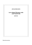
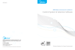
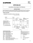
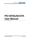
1
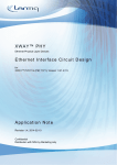
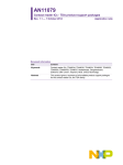
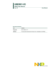
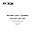
UM10338
Description of the TDA8029 I2C Demo Board
Rev. 1.0 — 11 January 2011
User manual
Document information
Info
Content
Keywords
TDA8029, I2C, Cake8029_12_D, Contact Smart Card Reader, PN533
Abstract
This user manual intends to describe the Cake8029_12_D. This demo
board is dedicated to the TDA8029 application with I2C interface.
The document also presents the connection between the TDA8029 board
and a PN533 demo board.
UM10338
NXP Semiconductors
Description of the TDA8029 I2C Demo Board
Revision history
Rev
Date
Description
1.0
First version
20110111
Contact information
For more information, please visit: http://www.nxp.com
For sales office addresses, please send an email to: [email protected]
UM10338
User manual
All information provided in this document is subject to legal disclaimers.
Rev. 1.0 — 11 January 2011
© NXP B.V. 2011. All rights reserved.
2 of 14
UM10338
NXP Semiconductors
Description of the TDA8029 I2C Demo Board
1. Introduction
1.1 TDA8029
The TDA8029 is a complete contact smart card reader. It embeds an electrical interface
with all the security features needed to protect the smart card, a fully compliant ISO 7816
UART, and a microcontroller with complete software driving the smart card protocols.
1.2 Demo Board
The Cake8029_12_D demo board is used to test the I²C interface of the TDA8029. On
the board the TDA8029 is configured for this interface, and this bus is physically the only
one implemented.
Therefore the board cannot be used with a serial interface.
The demo board is composed of
-
The TDA8029 device
-
A smart card connector
-
An interface connector, for the power supply and control signals.
-
Two configuration solder bridge (To choose using Energy Saving Mode or not)
-
A reset switch to reset the TDA8029
019aab234
Fig 1. Cake8029_12_D
UM10338
User manual
All information provided in this document is subject to legal disclaimers.
Rev. 1.0 — 11 January 2011
© NXP B.V. 2011. All rights reserved.
3 of 14
UM10338
NXP Semiconductors
Description of the TDA8029 I2C Demo Board
2. Hardware description
The next pages show the electrical schematics, the layout and the component position of
the board.
2.1 Schematics
J1
HE14_8MD
VDD
SDA
INT1
U1
CCM01_2251
C5I
C6I
C7I
C8I
P26
25
XTAL1
26
XTAL2
RESET
INT1
TX
TP9 GNDC
8
17
DCIN
SBP
TP13 VCC
C1I
C2I
C3I
C4I
ALE
EA
VDD
TEST
SAM
PGND
SBM
C6
C8
TP11 RST
220 nF
TP12 CLK
TP8 DCIN
C9
VDD
P27
PSEN
220 nF
C2
100 nF
K1
K2
TP3 SI2CM
16
18
15
7
14
19
SAP
R0
0Ω
20
6
9
TP7
PRES
5
13
PRES
TDA8029
VUP
I_O
21
IC1
12
100 nF
4
RST
TP6
I_O
CDEL
22
11
C5
3
VCC
SDWN
SDWN
23
10
GND
TP5
SDWN
P27
2
CLK
VDD
ST2
24
GNDC
SCL
1
P16
VDD
ST1
27
P17
TP4
SCL
31
32
RX
100 nF
C1
22 pF
14,745 MHz
28
C4
INT0
10 μF
16 V
C0
22 pF
Y1
29
C3
30
VDD
TP2 WUI2C
33 kΩ
DCIN
VDD
SDA
SCL
P27
INT1
SDWN
TP1 SDA
1
2
3
4
5
6
7
8
BP1
R1
C7
TP10 VUP
100 nF
220 nF
DCIN
C10
100 nF
C11
10 μF
16 V
019aab235
Fig 2. Cake8029_12_D – Schematics
UM10338
User manual
All information provided in this document is subject to legal disclaimers.
Rev. 1.0 — 11 January 2011
© NXP B.V. 2011. All rights reserved.
4 of 14
UM10338
NXP Semiconductors
Description of the TDA8029 I2C Demo Board
2.2 Layout Top
019aab236
Fig 3. Cake8029_12_D – Layout Top view
UM10338
User manual
All information provided in this document is subject to legal disclaimers.
Rev. 1.0 — 11 January 2011
© NXP B.V. 2011. All rights reserved.
5 of 14
UM10338
NXP Semiconductors
Description of the TDA8029 I2C Demo Board
2.3 Layout Bottom
019aab237
Fig 4. Cake8029_12_D – Layout Bottom view (transparent view)
UM10338
User manual
All information provided in this document is subject to legal disclaimers.
Rev. 1.0 — 11 January 2011
© NXP B.V. 2011. All rights reserved.
6 of 14
UM10338
NXP Semiconductors
Description of the TDA8029 I2C Demo Board
2.4 Components Top
J1
C5
C4
C3
C9
R0
C0
C7
IC1
Y1
C10
C11
C6
C8
ST1
C1
C2
ST2
BP1
019aab238
Fig 5. Cake8029_12_D – Components Top view
UM10338
User manual
All information provided in this document is subject to legal disclaimers.
Rev. 1.0 — 11 January 2011
© NXP B.V. 2011. All rights reserved.
7 of 14
UM10338
NXP Semiconductors
Description of the TDA8029 I2C Demo Board
2.5 Components Bottom
U1
019aab239
Fig 6. Cake8029_12_D – Components Bottom view
UM10338
User manual
All information provided in this document is subject to legal disclaimers.
Rev. 1.0 — 11 January 2011
© NXP B.V. 2011. All rights reserved.
8 of 14
UM10338
NXP Semiconductors
Description of the TDA8029 I2C Demo Board
2.6 Bill of Material
BP1
int_b3s
B3S_1000,
OMRON:Tact,Switch,6x6,SMT
C0
c0603
22pF,
Capacitor,CER2,0603,C0G,50V,5%
C1
c0603
22pF,
Capacitor,CER2,0603,C0G,50V,5%
C2
c0603
100nF,
Capacitor,CER2,0603,X7R,16V,10%
C3
c293d_c
10uF_16V,
Type,293D,Tantal,Capacitor,Package:C,10%
C4
c0603
100nF,
Capacitor,CER2,0603,X7R,16V,10%
C5
c0603
100nF,
Capacitor,CER2,0603,X7R,16V,10%
C6
c0603
220nF,
Capacitor,CER2,0603,X7R,10V,10%
C7
c0603
220nF,
Capacitor,CER2,0603,X7R,10V,10%
C8
c0603
220nF,
Capacitor,CER2,0603,X7R,10V,10%
C9
c0603
100nF,
Capacitor,CER2,0603,X7R,16V,10%
C10
c0603
100nF,
Capacitor,CER2,0603,X7R,16V,10%
C11
c293d_c
10uF_16V,
Type,293D,Tantal,Capacitor,Package:C,10%
IC1
sot358_1
TDA8029
J1
he14_1x8md
HE14_8MD,
HE14,Connector,1x8,Straight,Male
R0
r0603
0,
Resistor,Package:0603,5%,1/16W
R1
r0603
33K,
Resistor,Package:0603,5%,1/16W
ST2
chevron_clos
CLOSED,
***TO,BE,CLOSED***
TP1
plage.75
PLAGE.75,
***NOT,CONNECTED***
TP2
plage.75
PLAGE.75,
***NOT,CONNECTED***
TP3
plage.75
PLAGE.75,
***NOT,CONNECTED***
TP4
plage.75
PLAGE.75,
***NOT,CONNECTED***
TP5
plage.75
PLAGE.75,
***NOT,CONNECTED***
TP6
plage.75
PLAGE.75,
***NOT,CONNECTED***
TP7
plage.75
PLAGE.75,
***NOT,CONNECTED***
TP8
plage.75
PLAGE.75,
***NOT,CONNECTED***
TP9
plage.75
PLAGE.75,
***NOT,CONNECTED***
TP10
plage.75
PLAGE.75,
***NOT,CONNECTED***
TP11
plage.75
PLAGE.75,
***NOT,CONNECTED***
TP12
plage.75
PLAGE.75,
***NOT,CONNECTED***
TP13
plage.75
PLAGE.75,
***NOT,CONNECTED***
U1
ccm01_2251
CCM01_2251,
CANON:Card,Read,8,Contacts,SMT
Y1
hc49s
14.745MHZ,
KONY:Quartz,Crystal,Low,Profile,Package:HC49S
BUBBLE01:Printed_Circuit_board:PCB2075-1
BUBBLE02:ACME:ETL305015_Spacer_M3x15
BUBBLE03:Screw_C_M3x6_Stainless_Steel
BUBBLE04:INTER_INOX:A2M320_Lockwasher_Stainless_Steel
Fig 7. Cake8029_12_D – BOM
UM10338
User manual
All information provided in this document is subject to legal disclaimers.
Rev. 1.0 — 11 January 2011
© NXP B.V. 2011. All rights reserved.
9 of 14
UM10338
NXP Semiconductors
Description of the TDA8029 I2C Demo Board
3. Configuration and use
3.1 Energy Saving Mode
The two configuration switch ST1 and ST2 allow to choose if the Energy Saving mode is
used or not.
The connector connect the pin P26 (#25) to VDD or GND.
To use the ESM, ST1 must be soldered and ST2 open.
If the ESM is not used, ST2 must be soldered and ST1 unsoldered.
For more details on the Energy Saving Mode, refer to AN10207.
TP1
J1
a. ESM Off
TP12
TP11
TP2
TP4
C3
C4
TP5
C5
TP6
TP7
TP9
C9
TP13
C7
Y1
C1
C0
C2
TP3
ST2
ST1
TP1
IC1
TP10 R0 C10
C6 BP1
C8
TP8
C11
J1
TP12
TP11
TP2
TP4
C3
C4
TP5
C5
TP6
TP7
TP9
C9
TP13
C7
b. ESM On
Y1
C1
C0
C2
TP3
ST2
ST1
IC1
TP10 R0 C10
C6 BP1
C8
TP8
C11
019aab240
Fig 8. Cake8029_12_D – Energy Saving Mode configuration
UM10338
User manual
All information provided in this document is subject to legal disclaimers.
Rev. 1.0 — 11 January 2011
© NXP B.V. 2011. All rights reserved.
10 of 14
UM10338
NXP Semiconductors
Description of the TDA8029 I2C Demo Board
3.2 Interface connector
All the signals and power supply must come from the J1 connector.
The pin names are given in the schematics.
For a better representation, they are described on the board on the following picture:
TP1
1
J1
TP12
TP11
TP2
TP4
DCIN
C3
VDD
C4
SDA
TP5
SCL
C5
TP6
Slavel2CMute
TP7
WakeUpI2C
TP9
SDWN
C9
GND
TP13
C7
Y1
C1
C0
C2
TP3
ST2
ST1
IC1
TP10 R0 C10
C6 BP1
C8
TP8
C11
019aab241
Fig 9. Cake8029_12_D – Connector pins
The next table gives a description of each pin.
Table 1.
UM10338
User manual
Cake8029_12_D – Connector pins description
Pin number
Pin name
Description
1
DCIN
Power supply for the DC/DC converter. Must be in the
range from VDD to 6V
2
VDD
Power supply for the main chip. Must be in the range
2.7V – 6V
3
SDA
I2C bus – Data line
4
SCL
I2C bus – Clock Line
5
SlaveI2CMute
I2C bus – Line used by the TDA8029 to inform the host
that there is an event
6
WakeUpI2C
I2C bus – Line used by the host to wake up the TDA
before sending a frame
7
SDWN
Shutdown pin. Must be HIGH to use the TDA8029 and
LOW to put the TDA8029 in shutdown mode
8
GND
Power supply ground pin
All information provided in this document is subject to legal disclaimers.
Rev. 1.0 — 11 January 2011
© NXP B.V. 2011. All rights reserved.
11 of 14
UM10338
NXP Semiconductors
Description of the TDA8029 I2C Demo Board
3.3 Connection to a PN533 demo board
The PN533 embeds a software to be able to drive the TDA8029.
The PN533 generic demo board (PCB1950-1) has an external connector compatible with
the connector on the Cake8029_12_D.
The connection between the two boards can be achieved with a simple straight cable as
represented on the next picture.
019aab242
Fig 10. PN533 + TDA8029 – Boards connection
To use the board in this configuration, the connection ST1 must be closed and ST2 must
be unsoldered because the PN533 uses the Energy Saving Mode of the TDA8029.
For more detail on this application, refer to the PN533 Application Note dedicated to this
association: AN10758.
UM10338
User manual
All information provided in this document is subject to legal disclaimers.
Rev. 1.0 — 11 January 2011
© NXP B.V. 2011. All rights reserved.
12 of 14
UM10338
NXP Semiconductors
Description of the TDA8029 I2C Demo Board
4. Legal information
provide appropriate design and operating safeguards to minimize the risks
associated with their applications and products.
4.1 Definitions
Draft — The document is a draft version only. The content is still under
internal review and subject to formal approval, which may result in
modifications or additions. NXP Semiconductors does not give any
representations or warranties as to the accuracy or completeness of
information included herein and shall have no liability for the consequences
of use of such information.
4.2 Disclaimers
Limited warranty and liability — Information in this document is believed to
be accurate and reliable. However, NXP Semiconductors does not give any
representations or warranties, expressed or implied, as to the accuracy or
completeness of such information and shall have no liability for the
consequences of use of such information.
In no event shall NXP Semiconductors be liable for any indirect, incidental,
punitive, special or consequential damages (including - without limitation lost profits, lost savings, business interruption, costs related to the removal
or replacement of any products or rework charges) whether or not such
damages are based on tort (including negligence), warranty, breach of
contract or any other legal theory.
Notwithstanding any damages that customer might incur for any reason
whatsoever, NXP Semiconductors’ aggregate and cumulative liability
towards customer for the products described herein shall be limited in
accordance with the Terms and conditions of commercial sale of NXP
Semiconductors.
Right to make changes — NXP Semiconductors reserves the right to make
changes to information published in this document, including without
limitation specifications and product descriptions, at any time and without
notice. This document supersedes and replaces all information supplied prior
to the publication hereof.
Suitability for use — NXP Semiconductors products are not designed,
authorized or warranted to be suitable for use in life support, life-critical or
safety-critical systems or equipment, nor in applications where failure or
malfunction of an NXP Semiconductors product can reasonably be expected
to result in personal injury, death or severe property or environmental
damage. NXP Semiconductors accepts no liability for inclusion and/or use of
NXP Semiconductors products in such equipment or applications and
therefore such inclusion and/or use is at the customer’s own risk.
Applications — Applications that are described herein for any of these
products are for illustrative purposes only. NXP Semiconductors makes no
representation or warranty that such applications will be suitable for the
specified use without further testing or modification.
NXP Semiconductors does not accept any liability related to any default,
damage, costs or problem which is based on any weakness or default in the
customer’s applications or products, or the application or use by customer’s
third party customer(s). Customer is responsible for doing all necessary
testing for the customer’s applications and products using NXP
Semiconductors products in order to avoid a default of the applications and
the products or of the application or use by customer’s third party
customer(s). NXP does not accept any liability in this respect.
Export control — This document as well as the item(s) described herein
may be subject to export control regulations. Export might require a prior
authorization from national authorities.
Evaluation products — This product is provided on an “as is” and “with all
faults” basis for evaluation purposes only. NXP Semiconductors, its affiliates
and their suppliers expressly disclaim all warranties, whether express,
implied or statutory, including but not limited to the implied warranties of noninfringement, merchantability and fitness for a particular purpose. The entire
risk as to the quality, or arising out of the use or performance, of this product
remains with customer.
In no event shall NXP Semiconductors, its affiliates or their suppliers be
liable to customer for any special, indirect, consequential, punitive or
incidental damages (including without limitation damages for loss of
business, business interruption, loss of use, loss of data or information, and
the like) arising out the use of or inability to use the product, whether or not
based on tort (including negligence), strict liability, breach of contract, breach
of warranty or any other theory, even if advised of the possibility of such
damages.
Notwithstanding any damages that customer might incur for any reason
whatsoever (including without limitation, all damages referenced above and
all direct or general damages), the entire liability of NXP Semiconductors, its
affiliates and their suppliers and customer’s exclusive remedy for all of the
foregoing shall be limited to actual damages incurred by customer based on
reasonable reliance up to the greater of the amount actually paid by
customer for the product or five dollars (US$5.00). The foregoing limitations,
exclusions and disclaimers shall apply to the maximum extent permitted by
applicable law, even if any remedy fails of its essential purpose.
4.3 Trademarks
Notice: All referenced brands, product names, service names and
trademarks are property of their respective owners.
I2C-bus – logo is a trademark of NXP B.V.
Customers are responsible for the design and operation of their applications
and products using NXP Semiconductors products, and NXP
Semiconductors accepts no liability for any assistance with applications or
customer product design. It is customer’s sole responsibility to determine
whether the NXP Semiconductors product is suitable and fit for the
customer’s applications and products planned, as well as for the planned
application and use of customer’s third party customer(s). Customers should
UM10338
User manual
All information provided in this document is subject to legal disclaimers.
Rev. 1.0 — 11 January 2011
© NXP B.V. 2011. All rights reserved.
13 of 14
UM10338
NXP Semiconductors
Description of the TDA8029 I2C Demo Board
5. Contents
1.
1.1
1.2
2.
2.1
2.2
2.3
2.4
2.5
2.6
3.
3.1
3.2
3.3
4.
4.1
4.2
4.3
5.
Introduction .........................................................3
TDA8029 ............................................................3
Demo Board .......................................................3
Hardware description..........................................4
Schematics.........................................................4
Layout Top .........................................................5
Layout Bottom ....................................................6
Components Top................................................7
Components Bottom ..........................................8
Bill of Material.....................................................9
Configuration and use ......................................10
Energy Saving Mode ........................................10
Interface connector ..........................................11
Connection to a PN533 demo board ................12
Legal information ..............................................13
Definitions ........................................................13
Disclaimers.......................................................13
Trademarks ......................................................13
Contents.............................................................14
Please be aware that important notices concerning this document and the product(s)
described herein, have been included in the section 'Legal information'.
© NXP B.V. 2011.
All rights reserved.
For more information, please visit: http://www.nxp.com
For sales office addresses, please send an email to: [email protected]
Date of release: 11 January 2011
Document identifier: UM10338