1
D-Link® DKVM-IP1
1-port COMBO KVM Over IP
User Manual
v. 1.00
Table of Contents
1 Introduction.............................................................................................................. 4 1.1 Features ...................................................................................................................................5 1.2 Package Contents ....................................................................................................................6 1.3 Specifications ...........................................................................................................................7 1.4 System Requirements ..............................................................................................................8 1.5 Physical Diagrams....................................................................................................................9 1.6 Cable Connection Diagram ....................................................................................................10 1.7 Hardware Installation Procedure............................................................................................11 1.7.1 Connecting the DKVM-IP1 to a Host computer............................................................11 1.7.2 Connecting the DKVM-IP1 to a Multi-Port KVM Switch ...............................................12 1.8 When the server is up and running (Capabilities) ..................................................................13 1.9 When the computer/server fails (Diagnostics) .......................................................................14 2 Configuration ......................................................................................................... 15 2.1 Initial Network Configuration with the setup software ............................................................15 2.2 Configuration Setup via Serial-based Console ......................................................................20 2.3 Keyboard, Mouse, and Video configuration ...........................................................................21 2.3.1 DKVM-IP1 keyboard settings .......................................................................................22 2.3.2 Mouse settings for the Host and Remote systems.......................................................22 2.3.3 Mouse Synchronization Modes ....................................................................................24 2.3.4 Creating a Hotkey for Fast Sync/Free Mouse ..............................................................25 2.3.5 Synchronizing the Mouse Pointers (Double Mouse Mode) ..........................................26 2.3.6 Troubleshooting Mouse Synchronization (Double Mouse Mode) ................................27 2.3.7 Video Modes.................................................................................................................28 3 Usage...................................................................................................................... 29 3.1 Prerequisites ..........................................................................................................................29 3.1.1 3.2 3.2.1 HTTP as the Primary Interface.....................................................................................29 Logging into or out of the DKVM-IP1 .....................................................................................32 Logging in .....................................................................................................................32 1 3.2.2 Using the Web GUI.......................................................................................................33 3.2.3 Host Console Preview ..................................................................................................35 3.3 The Host Console...................................................................................................................36 3.3.1 Opening the Host Console window ..............................................................................37 3.3.2 Control Bar of the Host Console...................................................................................39 3.3.3 Host Console window Status Bar .................................................................................48 4 Menu Options of the Web Management GUI....................................................... 49 4.1 Remote Control ......................................................................................................................49 4.1.1 KVM Console................................................................................................................49 4.1.2 Telnet Console .............................................................................................................50 4.1.3 Remote Wakeup...........................................................................................................55 4.2 Virtual Media ..........................................................................................................................60 4.2.1 Drive Redirection ..........................................................................................................62 4.2.2 Virtual Drive ..................................................................................................................64 4.2.3 CD/DVD Disk Image.....................................................................................................65 4.2.4 Floppy Disk Image........................................................................................................69 4.2.5 Creating a Disk Image ..................................................................................................72 4.2.6 Making a Drive Redirection ..........................................................................................74 4.3 User Management..................................................................................................................78 4.3.1 Change Password ........................................................................................................78 4.3.2 User Management ........................................................................................................79 4.4 KVM Settings..........................................................................................................................81 4.4.1 User Console................................................................................................................81 4.4.2 Keyboard/Mouse ..........................................................................................................85 4.4.3 Video.............................................................................................................................86 4.5 Device Settings ......................................................................................................................87 4.5.1 Network.........................................................................................................................87 4.5.2 Dynamic DNS ...............................................................................................................90 4.5.3 Security.........................................................................................................................93 4.5.4 Certificate......................................................................................................................96 2 4.5.5 Serial Port...................................................................................................................100 4.5.6 Date/Time ...................................................................................................................102 4.5.7 Event Log....................................................................................................................104 4.5.8 Authentication.............................................................................................................108 4.5.9 USB ............................................................................................................................110 4.5.10 Config File...................................................................................................................110 4.6 Maintenance.........................................................................................................................111 4.6.1 Device Information......................................................................................................111 4.6.2 Event log.....................................................................................................................112 4.6.3 Update Firmware ........................................................................................................113 4.6.4 Unit Reset...................................................................................................................115 5 Resetting the DKVM-IP1 to Factory Defaults .................................................... 116 6 FAQ ....................................................................................................................... 117 7 Troubleshooting .................................................................................................. 118 8 Addendum............................................................................................................ 124 8.1 Key Codes............................................................................................................................124 8.2 Video Modes ........................................................................................................................126 8.3 User Role Permissions.........................................................................................................127 8.4 Suggested Video Settings for Different Bandwidths ............................................................128 8.5 Well-known TCP/UDP Port Numbers...................................................................................129 8.6 Protocol Glossary .................................................................................................................130 3 1 Introduction
NOTE: In this manual, the term “Host” and “Host system” refers to the computer or
server that is connected to the DKVM-IP1. This is therefore the computer/server that can
be remotely controlled from a “Remote” computer by an administrator, or “Remote-side
user”. The term “Host Console” refers to the redirected view of the video monitor that is
connected to the “Host” computer – as it is displayed in a window on the Remote
computer that is controlling or monitoring the Host system. The term “local” refers to
things that are in close physical proximity to a specified system. For instance, the “local”
console (KVM controls) of the Host system will be redundant during the periods when the
Remote-side user controls the Host system with his or her “local” console. For the
purpose of clarity, these terms will be capitalized in sentences where it needs to be made
clear that the term refers to the user-manual-specific definition of the word (Remote, Host,
Local, etc.), and not the general definition of the word.
The DKVM-IP1 provides convenient, remote KVM access and control via LAN or Internet.
It is installed on the Host side and transmits a Remote computer’s control INPUT (mouse
and keyboard) to the Host computer. It also captures, digitizes, and compresses the
video OUTPUT signal of a Host computer and then transmits it to the Remote computer.
This DKVM-IP1 provides a non-intrusive solution for remote access and control all the
way down to the BIOS level of the Host. The remote access and control software only
runs on the device’s embedded processors, not on mission-critical servers, so it does not
interfere with server operations, or affect network performance.
This means that administrators can securely gain BIOS-level access to remotely located
computers for maintenance, support, failure recovery, and even remote wakeup over the
Internet or LAN. All communications are secured by SSL authentication and encryption.
This DKVM-IP1 can be used in conjunction with a KVM Switch for remote access to
multiple computers.
4 1.1
Features
KVM Over IP
Manage servers remotely from anywhere
Remote KVM (keyboard, video, and mouse) access over the Internet, or analog telephone
line (modem needed)
USB Host-side computer interfaces
Full control in any OS – in BIOS level, during boot-up, or in normal operating mode
Remote power wakeup on the Host computer
Remotely controlled mass storage and redirection
Remote control over Java-enabled Browsers
No additional software needed on client console side
SSL secure access through certified authentication and data encryption
256-bit SSL encryption binding with all transmitted data
Persistent logging of all important events
Up to 63 user profiles that can each be assigned to one of three levels of user authorization
Auto-optimization of the frame rate and video quality according to bandwidth availability
Automatic sensing of video resolution for best possible screen capture
High-performance mouse tracking and synchronization
Firmware updates via web interface
KVM Transmission
Transmission of video signals through a Remote computer with support for screen
resolutions up to 1600 x 1200 at 60 Hz with 16/8/4/2/1-bit video encoding and manual and
automatic adjustment
Supports all standard VGA and VESA modes (graphics and text)
Works with all web browsers
5 Network access
Access via 10/100 Mbps LAN
Communication over TCP/IP port 80 and port 443 (reconfiguration possible)
IP-configuration via DHCP/BOOTP or static IP
HTTP and HTTPS (secure) Web Server
Works with standard Hayes-compatible modems
Supports modem speeds of up to 115200 bps
Automatic adjustment of the video-compression ratio according to available bandwidth
1.2
Package Contents
The product you purchased should contain the equipment and accessories in this list:
1-port Combo KVM Over IP device (DKVM-IP1)
External power adapter DC 5 V / 2 A
RS-232 (Female-to-Female) cable 1.8 m (null modem type)
3-in-1 cable containing a PS/2 keyboard cable, a PS/2 mouse cable, and a VGA cable
USB cable (1 Type A Male to 1 Type B Male connector) to connect the DKVM-IP1 to the Host
system for file sharing, or as an alternative connection (USB) for the Host’s keyboard and
mouse.
CD-ROM (software utilities and user manual)
6 1.3
Specifications
Specifications
Number Of Computers Controlled
1
Red for PC Linking
LEDs
Green for IP Ready
Compliant with these USB Versions
USB1.0 / USB1.1 / USB2.0
Compliant with this HID Version
USB HID 1.11
Video
1 x HDB-15 (Male)
USB (KB & MS)
1 x USB B-type (Female)
PS2 Keyboard
1 x PS/2 mini-DIN 6-pin (Female)
PS2 Mouse
1 x PS/2 mini-DIN 6-pin (Female)
Video
1 x HDB-15 (Female)
Keyboard
1 × PS/2 mini-DIN 6-pin (Female)
Mouse
1 × PS/2 mini-DIN 6-pin (Female)
PC Connectors
Console Ports
Firmware upgrade connector
1 x mini USB (Female)
Serial port
1 x RS-232 (Male)
Ethernet port
1 x RJ45
Virtual media port
1 x USB B-type (Female)
Remote computer screen resolution
Up to 1600 x 1200 at 60 Hz
DDC, DDC2 Monitor
Supports DDC2B,
(max resolution up to 2048 x 1536 at 60 Hz)
Operating systems supported
Windows 98 / 98SE / ME / 2000 / XP / Vista / 7 / 2003,
Mac OS 9 / OS X, Linux, Sun Micro OS
Power
By external power adapter – DC 5 V / 2 A
Hot-pluggable
Yes
Device driver
No
Dimensions (LxWxH)
27.5 x 7.8 x 3.8 cm (10.8 x 3.1 x 1.5 inches)
Unit Weight
780 g (1.72 lb)
Housing material
Metal
7 Operating Temperature
32 to 122 °F (0 to 50 °C)
Storage Temperature
4 to 140 °F (-20 to 60 °C)
Humidity
0% to 80%RH
1.4
System Requirements
Hardware
On the Host computer/server side:
On the Host console side:
One computer, or a server, or a serial console.
A PS/2 keyboard and mouse, and one VGA monitor. (These peripherals will only be
needed for normal operation and will become redundant during the periods when the
Host computer will be controlled remotely via the DKVM-IP1.)
On the Remote computer side:
Any computer that is connected to the same network that the target DKVM-IP1 is
connected to, whether that be a LAN or the Internet.
Software on the Remote computer
Java Runtime Environment : version 1.5 or above
Browser: Microsoft Internet Explorer 6 or above, Netscape, Mozilla, or Safari
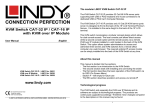
8 1.5
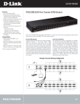
Physical Diagrams
Front View
Rear View
LED
Functions
PC-Link
Red – indicates that the DKVM-IP1 is linked to a PC
Ready
Green – blinks once every second when the system
is ready
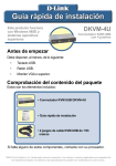
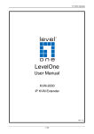
9 1.6
Cable Connection Diagram
10 1.7
Hardware Installation Procedure
1.7.1
Connecting the DKVM-IP1 to a Host computer
1.
Turn off your computer and DKVM-IP1.
2.
Connect the DKVM-IP1 to the Host computer (the computer that will be controlled from
a remote location):
a.
Have the relevant USB, PS/2 (keyboard and mouse) and VGA connectors ready
for connecting to the Host computer.
b.
Ensure that the connector types you want to connect (USB, PS/2) are supported by
your computing systems. Some computer systems only support one of the two
types.
c.
Connect your VGA connectors and other supported connectors (USB or PS/2 or
both) to the Host computer. Follow the guidelines below:
VGA: Use the included VGA cable to connect the Host computer's VGA Out
port to the DKVM-IP1's VGA In port. Use another VGA cable(not included) to
connect the DKVM-IP1's VGA Out port to your Host computer's monitor.
PS/2 (front): (optional) The PS/2 ports in the front (the “clean” or “face” side) of
the DKVM-IP1 can be used to connect a PS/2 keyboard and mouse for direct
control of the Host computer by Host-side users. This saves the trouble of
unplugging any cables when Local (Host-side) control is required.
PS/2 (back): Use the included PS/2 keyboard and mouse to connect the PS/2
mouse/keyboard ports on the back of the DKVM-IP1 to the mouse/keyboard
ports on the Host computer. Alternatively, if you will be using a USB mouse
and keyboard to control the Host computer, you can use the USB port instead.
(refer to next step)
USB (Keyboard and Mouse): If you will be using a USB mouse and keyboard
to control the Host computer(such as if the Host computer does not have PS/2
ports), use a Type A(male) to Type B(male) USB cable(one is included in your
package) to connect the USB Keyboard/Mouse port on the DKVM-IP1 to an
available USB port on the Host computer.
Ethernet: Use an Ethernet cable(one is included in your package) to connect
the Ethernet port of the DKVM-IP1 to your local network. This local network
will need to be connected to either the remote computer you will use to control
the Host computer, or to the Internet. If you wish to remotely control the Host
11
USB (Data): (optional) Use a Type A(male) to Type B(male) USB cable(one is
included in your package) to connect the USB Data port on the DKVM-IP1 to
an available USB port on the Host computer. This allows the Remote
computer to access mass storage devices connected to, or inside, the Host
computer.
3.
Connect the Remote computer to the same network that the DKVM-IP1 is connected to,
whether that would be a LAN or the Internet.
NOTE:
Connect all cables to the Host computer, Host Console devices, DKVM-IP1, and
relevant network as depicted in the Cable Connection Diagram above.
After switching on the DKVM-IP1, it will take about 60 seconds to complete the
startup process before entering normal operational mode.
1.7.2
Connecting the DKVM-IP1 to a Multi-Port KVM Switch
Instead of connecting to a single Host computer, the DKVM-IP1 can be connected to a
multi-port KVM Switch on the Host side. In this scenario, the DKVM-IP1 and KVM Switch will be
connected directly to give the Remote computer control over any one of the computers
connected to the KVM Switch. Follow the steps in the previous section, but instead of
connecting the cables to the Host PC, connect them to the multi-port KVM switch.
12 1.8
When the server is up and running (Capabilities)
The DKVM-IP1 gives the user of the Remote computer full control over devices that are
connected to the DKVM-IP1 on the Host side. These connected devices could be single
computers or servers, or multiple computers or servers that are connected to the
DKVM-IP1 through a KVM Switch. The DKVM-IP1 comes pre-loaded with
web-management firmware (GUI) that allows a Remote-side administrator to manage the
settings of the DKVM-IP1 via the Internet. The firmware also allows the Remote-side
user to control the keyboard and mouse input of the Host system, as well as view the
video output of the Host computer/server that is connected to the DKVM-IP1. In addition,
it allows the Remote-side user to send special commands to the Host, and it lets the
Remote-side user perform periodic maintenance of the Host. From the Host Console
window on the Remote computer, you can do the following:
Reboot the Host system
Monitor the Host’s boot process
Boot the Host system from a separate partition to load the diagnostic environment
Run special diagnostic programs on the Host system
13 1.9
When the computer/server fails (Diagnostics)
Unfortunately, fixing hardware defects is not possible through a remote management
device. However, the DKVM-IP1 does give the administrator valuable information about
the type of a hardware failure.
When the computer/server fails, the Remote computer user can see the error message
from the computer/server on his or her screen.
With the DKVM-IP1, Remote-side administrators can determine which kind of hardware
failure has occurred on the Host system.
Serious hardware failures can be categorized into five different categories. These
categories are listed below, together with the percentage of times that such failures
were caused by the specific type of problem.
See the table below for a list of Host system failures and how they are detected.
Type of failure
Detected by
Hard disk failure (50% of all failures)
Console screen, CMOS set-up information
Power cable detached; power
Server remains in Power Off state after Power
supply failure (28% of all failures)
On command has been given
CPU, controller, main board failure
Power supply is on, but there is no video output
(10% of all failures)
CPU fan failure (8% of all failures)
Server-specific management software
RAM failure (4% of all failures)
Boot sequence on boot console
Above: Host system failures and how they are detected.
14 2 Configuration
2.1 Initial Network Configuration with the setup software
After the initial setup, the DKVM-IP1 can be managed via a web management program
(GUI) that lets you control the device/s attached to it. However, to configure the
DKVM-IP1’s network access, the user must first run the DKVM-IP1 Utility software that is
included on the CD-ROM included in your package (DKVM-IP1_Utility.exe).
The DKVM-IP1 Utility lets you set up the DKVM-IP1’s network configuration (IP address,
Subnet mask, DHCP, etc) from any computer that is connected to the same subnet. This
program is also useful if you ever need to view or change the network settings of the unit.
If the initial or default basic configuration does not meet your requirements, use the
DKVM-IP1_Utility.exe program to change the configuration to suit your needs.
To open the DKVM-IP1 Utility on your computer, simply insert the CD-ROM and
double-click on the DKVM-IP1_Utility.exe icon when the CD-ROM’s content window
appears. The DKVM-IP1 Utility window (see the screenshot below) will appear.
Above: The network setup screen of the DKVM-IP1 Utility program.
To use the DKVM-IP1 Utility, please follow the procedures described below.
Finding the DKVM-IP1 on your network via the DKVM-IP1 Utility:
1) Make sure the computer you are using to set up the DKVM-IP1 is connected to the
same local network that the DKVM-IP1 is connected to.
15 2) Open the DKVM-IP1 Utility on your computer by simply inserting the CD-ROM and
double-clicking on the DKVM-IP1_Utility.exe icon when the CD-ROM’s content
window appears. The DKVM-IP1 Utility window (see the screenshot above) will
appear.
3) Use the DKVM-IP1 Utility to search for the DKVM-IP1 on your network:
a) Click the Refresh Devices button to show the MAC addresses of all
connected devices on your network.
b) Find the MAC address of the DKVM-IP1 by clicking on the “Device MAC
Address” drop-down box. Select your device’s MAC address from the
dropdown list. You can find your DKVM-IP1’s MAC ID on a label located on
the bottom of your DKVM-IP1 (see the image below).
Left: The label on the
bottom of each
DKVM-IP1 shows the
unique MAC ID of the
device. This ID is the
same as the MAC
Address.
c) After selecting your DKVM-IP1’s MAC address, click Query Device (see the
screenshot below) to view the device’s Network Configuration in the top right
area.
d) By default, the DHCP function is disabled, and “None” will be selected for “IP
auto configuration”. This means there would initially be no IP address for the
device. You can now configure the DKVM-IP1 to use a static IP address, or
you can turn on DHCP to automatically obtain an IP address from a DHCP
server on your network. Both configurations are described in the following
steps.
Note: We recommend that you manually set up a static IP address that is
linked to the MAC address of your DKVM-IP1.
Setting up a static IP via the DKVM-IP1 Utility:
1) Make sure that the correct MAC address is selected in the “Device” field at the top
left of the DKVM-IP1 Utility window.
2) Click Query Device (at bottom right) to view the device’s Network Configuration in
the top right area.
16 3) In the “IP auto configuration” line at the top right, select “None”.
4) Enter the IP address, subnet mask, and gateway you want the DKVM-IP1 to use.
5) In the Authentication area, enter the Super User login and password for the
DKVM-IP1. The default login is super, and the default password is pass.
6) Click the Setup Device button. If the Super User login and password are correct, a
“Successfully configured device” message will appear. Otherwise, the message
“Permission Denied” will appear.
7) The DKVM-IP1’s web management interface can now be accessed via the Internet
by simply browsing to the same IP address from a web browser.
Enabling DHCP to get a dynamic IP address:
If you have installed the DKVM-IP1 on the subnet (intranet) of a DHCP server, or the
subnet of a router that supports DHCP, you can use the DKVM-IP1 Utility to find the
dynamic IP address of the DKVM-IP1. DHCP automatically assigns a dynamic IP
address to the DKVM-IP1. This allows a device to be automatically assigned an IP,
eliminating the need for intervention by a network administrator, who would otherwise
have to manually assign the DKVM-IP1 a static IP address.
1) Before connecting the DKVM-IP1 to your network, make sure you complete the
configuration of the network’s DHCP server. The network’s router may be acting as
your network’s DHCP server, or another device may be acting as the DHCP
server.
2) Connect the DKVM-IP1 to your network by using an Ethernet cable. Connect one
end to your network, and the other end to the Ethernet port of the DKVM-IP1.
3) The DHCP function of the router/server will now automatically assign an IP
address to the DKVM-IP1.
4) Make sure that the computer you are using to set up the DKVM-IP1 is connected
to the same network that the DKVM-IP1 is connected to.
17 5) Open the DKVM-IP1 Utility on your setup computer by simply inserting the
CD-ROM and double-clicking on the DKVM-IP1_Utility.exe icon when the
CD-ROM’s content window appears. The DKVM-IP1 Utility window (see
screenshot above) will appear.
6) Use the DKVM-IP1 Utility to search for the DKVM-IP1 on the network (see the
image below):
a) Click the Refresh Devices button to detect all connected devices.
b) Find the MAC address of the DKVM-IP1 by clicking on the “Device MAC
Address” drop-down box. Select your device’s MAC address from the
dropdown list. You can find your DKVM-IP1’s MAC ID on a label located on
the bottom of your DKVM-IP1 (see the image below).
Left: The label on the
bottom of each
DKVM-IP1 shows the
unique MAC ID of the
device. This ID is the
same as the MAC
Address.
c) After selecting your DKVM-IP1’s MAC address, click Query Device (see the
screenshot below) to view the device’s Network Configuration in the top right
area.
d) In the “IP auto configuration” line at the top right, select “DHCP”.
e) In the Authentication area, enter the Super User login and password for the
DKVM-IP1. The default login is super, and the default password is pass.
f) Click the Setup Device button. If the Super User login and password are
correct, a “Successfully configured device” message will appear. Otherwise,
the message “Permission Denied” will appear.
g) The DKVM-IP1 will now try to contact a DHCP server in the subnet to which it
is physically connected. If contact is made with a DHCP server, it will provide
the DKVM-IP1 with a dynamic IP address, subnet mask, and gateway.
h) Click the Query Device button again, and the device’s dynamic IP address
and other network information should now be visible in the Network
Configuration field (see the screenshot below).
18 Notes:
BOOTP
is a static configuration protocol that uses a table that maps IP
addresses to physical addresses.
DHCP
is an extension of BOOTP that dynamically assigns configuration
information. DHCP is backwards compatible with BOOTP.
The factory default settings for the DKVM-IP1 unit are as below:
DHCP: Disabled
Default IP address: 192.168.0.70
Default Subnet mask: 255.255.255.0
IN SHORT: If the currently selected device has DHCP selected for its Network
Configuration, click OK and the DKVM-IP1 will try to contact a DHCP server in the
network to which it is physically connected. If contact is made with a DHCP server, it will
provide the DKVM-IP1 with a dynamic IP address, gateway address and subnet mask.
NB: Changing your device’s password through the DKVM-IP1 Utility:
To change your password with the DKVM-IP1 Utility, select your device from the Device
MAC Address drop-down box, then in the “Authentication” section in the bottom-left part
of the window, enter the Super User login and current password for your DKVM-IP1. The
default login is super, and the default password is pass. Now enter your new password
in the “New Super User password” text box, and enter it again in the “New Password
(confirm)” text box to confirm it.
19 To save your new password and close the window, click the OK button. Otherwise, click
the Cancel button.
WARNING:
Please make sure that you change the default Super User password immediately
after you have installed and accessed your DKVM-IP1 for the first time. Leaving
the password as it is represents a severe security risk and may result in
unauthorized access to the DKVM-IP1 as well as the entire Host system and
connected devices. The password can be changed in the setup program (as
described above) or online on the browser-based Web Management GUI. Make
sure you write your password down in a safe place.
NOTE:
Your web browser has to be set up to accept cookies, or else you won’t be able to
log in. If you experience login problems, check to see if your browser has been set
up to accept cookies.
2.2
Configuration Setup via Serial-based Console
For connecting to serial-based terminals, the DKVM-IP1 has a serial cable interface (for
setup on the Host side). This connector is compliant with the RS-232 standard for serial
connections. The serial connection has to be configured with the parameters given in the
table below.
Parameter
Value
Bits per second
115200
Data bits
8
Parity
No
Stop bits
1
Flow Control
None
When configuring your device from a serial-based terminal such as Hyper Terminal, reset
the DKVM-IP1 and immediately press the “ESC” key. You will see some device information
and a “=>” command prompt. Type in “config”, press the “Enter” key and wait a few
seconds for the configuration questions to appear.
20 As you proceed, you will be prompted for the following settings one after the other. To
accept the default value for a setting shown in square brackets below, press the “Enter”
key.
IP auto configuration: (empty field)
IP address: [192.168.0.70]
Net mask: [255.255.255.0]
Gateway: [0.0.0.0] -- (0.0.0.0 means “none”)
IP auto-configuration
You can specify whether the DKVM-IP1 should get its network settings from a DHCP or
BOOTP server. To enable IP auto-configuration via DHCP, type “dhcp” in the “IP
auto-configuration” line. For BOOTP, type “bootp”. Press “Enter” to apply the setting.
If you do not specify either of these two options, IP auto-configuration will be disabled(it will
be static IP configuration) and you will be asked for the following network settings:
IP address
Enter the IP address of the DKVM-IP1. This option is only available if “IP
auto-configuration” is disabled.
Net mask
Enter the subnet mask of the connected IP subnet. This option is only available if “IP
auto-configuration” is disabled.
Gateway address
Enter the IP address of the default router for the connected IP subnet. If you do not have a
default router, enter 0.0.0.0. This option is only available if “IP auto-configuration” is
disabled.
2.3
Keyboard, Mouse, and Video configuration
This DKVM-IP1 device gives you the option of using either the USB or PS/2 interface to
transmit keyboard and mouse input data (from the Remote computer) to the DKVM-IP1
and the Host. These ports are situated next to each other at the back of the device. (The
DKVM-IP1 also features secondary PS/2 ports on the front of the device, so that
Host-side users can attach a PS/2 keyboard and mouse to the DKVM-IP1, for direct
Local control of the Host machine, on the Host side.)
21 The following settings must be configured to ensure that the Remote keyboard, video,
and mouse inputs are transmitted correctly:
2.3.1
DKVM-IP1 keyboard settings
The keyboard model emulated by the DKVM-IP1 must be set properly in order for
keystrokes received by the Host computer to match the ones sent by a Remote computer.
View these settings in the DKVM-IP1’s Web Management GUI by clicking KVM Settings
> Keyboard/Mouse Settings (see the screenshot below).
Above: Click on KVM Settings > Keyboard/Mouse in the left-hand panel of the Web
Management GUI to configure the correct settings for the keyboard model to emulate for
the Host computer. The correct settings are required for the Remote keyboard’s input to be
transmitted to the Host computer properly.
2.3.2
Mouse settings for the Host and Remote systems
A common problem with KVM devices is the synchronization between the Host-side and
Remote-side mouse cursors. The DKVM-IP1 addresses this problem with an intelligent
synchronization algorithm.
22 NOTE:
The best results for mouse synchronization are obtained when both machines run on
optimal operating systems. For instance, good results can be obtained when both systems
run versions of Windows that are either Windows 2000 or later. Mac OS X devices also deliver
good results. Check the information below for OS-specific settings and limitations.
For obtaining the best mouse sync results on Windows systems, first go to your
DKVM-IP1’s web GUI and go to KVM Settings > Keyboard/Mouse.
In KVM Settings > Keyboard/Mouse, select Auto for your Mouse Speed. Click Apply
to save your changes.
Windows 2000 (on Host computer): On the Host computer, you will need to go to
Control Panel > Mouse > Motion > Acceleration and make sure “Improve Mouse
Acceleration” is disabled.
Windows XP/Vista/7 (on Host computer): On the Host computer, you will need to go to
Control Panel > Mouse > Pointer Options and make sure “Enhance Pointer Precision” is
disabled.
On the Remote computer, go to the web GUI screen and open the Host Console window.
Click the “Auto Adjust Video” button (
For best results, click the button with the white mouse pointer icon at the top right of the
) at the top right of the Host Console window.
Host Console window until it displays two pointers side by side (Double Mouse Mode).
This mode works well for most operating systems.
Click on the Host Console window to activate the second pointer.
The Remote mouse pointer will move faster than the darker Host pointer. However, the
Host pointer should quickly catch up with the Remote pointer once it stops. The Host
pointer should sync perfectly with the Remote pointer a few moments after the
Remote pointer comes to a stop.
If the Host pointer does not sync perfectly after a second or two, click the “Sync” icon at
the top right of the Host window.
Click on the Host Console window again and test the pointers to see if they sync when
the Remote pointer comes to a stop.
23 There are two mouse speed modes available on the DKVM-IP1:
Auto mode
The auto mouse speed mode tries to detect the speed and acceleration settings of the
Host system automatically. (See section 2.3.3 below for a more detailed explanation.)
Above: In this zoom-in screenshot of the Keyboard/Mouse Settings web page, “Mouse
speed – Auto” mode is disabled, “Fixed scaling” is active and set to 4, although a setting
of 1 might work better on some computers.
Fixed scaling mode
This mode translates the mouse movements from the Remote computer so that one pixel
of movement will result in “n” number of pixel moves on the Host computer. The value of
“n” is adjustable (see screenshot above). Please note that this works only when mouse
acceleration settings are turned off on the Host computer. See the previous note for
instructions on how to do this on different editions of Windows.
2.3.3
Mouse Synchronization Modes
The DKVM-IP1 features two different mouse synchronization modes: Double Mouse
mode, and Single Mouse mode.
Double Mouse Mode: In this mode, both the Remote and Host mouse pointers are
visible, allowing you to control the Host computer on your Remote computer while
allowing you to move the mouse outside the Host Console window. In this mode, the
mouse pointers may need to be synchronized in order to ensure they are pointing at the
same position on your Host computer screen. You can define a hotkey to quickly sync
the two mouse pointers.
Single Mouse Mode: In this mode, only one mouse pointer is visible – the Remote
computer pointer. On the Remote computer, when you click on the Host Console window,
your mouse pointer will be “captured”, and all mouse movement will be inside the Host
Console window only. In order to “free” the Remote computer’s mouse pointer, you will
24 need to use a hotkey to “release” the mouse pointer from the Host Console window. The
default hotkey for this is “Alt + F12”.
2.3.4
Creating a Hotkey for Fast Sync/Free Mouse
A Fast Sync/Free Mouse hotkey can be defined by going to KVM Settings > User
Console in the DKVM-IP1’s web GUI. After opening this screen, go to the Mouse Hotkey
field and type in your choice of keystroke sequence. Click “Apply” to activate the hotkey
sequence (see the image below).
Note: The default hotkey for the Fast Sync/Free Mouse function is Alt+F12.
When in Double Mouse mode, this hotkey will perform a Fast Sync.
When in Single Mouse mode, this hotkey will release the mouse from the
captured state it enters when the Remote user clicks on the Host Console
window.
Above: The Mouse Hotkey can be configured by clicking KVM Settings > User Console.
25 2.3.5
Synchronizing the Mouse Pointers (Double Mouse Mode)
In Double Mouse Mode, whenever the Host-side and Remote-side mouse cursors move
non-synchronously, you will need to synchronize them. To do this, you can use a Fast
Sync, or Intelligent Sync.
Fast Sync
To synchronize the mouse pointers, click the “Sync” button at the top right corner of the
Host Console window.
Above: The “Sync” icon can be found at the top right of the Host Console window on the
Remote computer’s screen.
This is used to correct a temporary, but fixed difference in positions of the Remote and
Host mouse pointers.
You can also perform a Fast Sync by pressing the Fast Sync/Free Mouse hotkey
combination, as described in the previous section.
Intelligent Sync
Above: The “Intelligent Sync” option can be found by clicking on Options > Mouse
Handling.
If Fast Sync does not work, or if the mouse settings have been changed on the Host
computer, you can use Intelligent Sync. This method will take more time than Fast Sync.
It can be accessed by clicking the “Options” button on the top right of the Host Console
26 window on the Remote computer’s screen. After opening the Options menu(as seen in
the above image), click on “Mouse Handling > Intelligent Sync”.
NOTE:
Intelligent Sync requires a correctly adjusted picture; click the “Auto Adjust
Video” button (
) to automatically adjust the picture. After initial setup and/or
startup, if the Host-side mouse pointer is not synchronized with the Remote-side
mouse pointer, click the “Auto Adjust Video” button once before applying
“Intelligent Sync”.
2.3.6
Troubleshooting Mouse Synchronization (Double Mouse Mode)
While the DKVM-IP1 supports accelerated mouse movements and is able to synchronize
the Host-side pointer with the Remote-side mouse pointer, there are a few operating
systems that limit this functionality and may prevent this synchronization from working
properly. If you experience issues with mouse synchronization, please try the following:
Special Mouse Drivers
Specific mouse drivers may influence the synchronization process and impede
synchronization of dual mouse pointers. If this happens, make sure you are not using a
special vendor-specific mouse driver on your Host system.
Windows Settings
All versions of Windows (on Host computer): In the DKVM-IP1’s web GUI, select
“Auto Mouse Speed” (in KVM Settings > Keyboard/Mouse).
Windows 2000 (on Host computer): On the Host computer, you will need to go to
Control Panel > Mouse > Motion > Acceleration and make sure “Improve Mouse
Acceleration” is disabled.
Windows XP/Vista/7 (on Host computer): On the Host computer, you will need to go to
Control Panel > Mouse > Pointer Options and make sure “Enhance Pointer Precision”
is disabled.
Active Desktop: If the “Active Desktop” feature of Microsoft Windows is enabled, do not
use a plain background. Instead, use a wallpaper image. Alternatively, disable “Active
Desktop” completely.
27 Mac OS X Settings
Mac OS X (on Host computer): If the host computer is running on any version of
Mac OS X, we recommend using Single Mouse mode.
SUN Solaris Settings
SUN Solaris (on Host computer): If the host system is running SUN Solaris, adjust
the mouse settings of the system by entering “xset m 1” into the console, or use the
CDE Control Panel to set the mouse to “1:1, no acceleration”. Alternatively, you
could use the Single Mouse mode only. On SUN operating systems, Double Mouse
Mode only functions if you use SUN JVM 1.5 or higher.
2.3.7
Video Modes
The DKVM-IP1 recognizes a limited number of common video modes. If you run X11 on
the Host system, please do not use any custom mode lines with special video modes. If
you do, the DKVM-IP1 may not be able to detect them. We recommend using any of the
standard VESA video modes instead.
28 3
Usage
3.1
Prerequisites
The DKVM-IP1 features an embedded operating system and applications that support
two standardized interfaces – HTTP/HTTPS and Telnet. This chapter will describe both
these interfaces in detail, as well as how to use them. Both interfaces are accessed
using the TCP/IP protocol family.
■ HTTP and HTTPS
Full access is provided by the device’s embedded web server. The DKVM-IP1
environment can be managed completely by using a standard web browser. You can
access the DKVM-IP1 by using the non-secure HTTP protocol, or by using the
encrypted HTTPS protocol. For security purposes, we suggest using HTTPS whenever
possible.
■ Telnet
A standard Telnet client can be used to access any device that is connected to
the DKVM-IP1’s serial port (RS-232) in terminal mode.
3.1.1
HTTP as the Primary Interface
The primary interface of the DKVM-IP1 is the HTTP web interface. This will be covered
extensively in this chapter. Other interfaces will be addressed in sub-topics.
The “Host Console” window is the redirected view of the Host screen that is displayed in
a window on the Remote computer. In order to open the Host Console window of your
managed Host system, the browser must support version 1.5 or above of the Java
Runtime Environment. If the browser has no Java support (such as the browser on a
small handheld device), you can still manage your DKVM-IP1 by using the administration
forms displayed by the browser itself.
29 Above: The web management interface of the DKVM-IP1. To get to this “User Management”
page, click on UserManagement > Users in the left-hand panel.
For a secure connection to the DKVM-IP1, we recommend the following web browsers:
■ Microsoft Internet Explorer 6 or higher
■ Netscape Navigator 7 or higher
■ Mozilla Firefox 1.6 or higher
In order to access the remotely located Host system through a securely encrypted
connection, you need a browser that supports the HTTPS protocol. Strong security is
only assured by using a browser that supports a 128-bit passkey. Some older browsers
do not have strong 128-bit encryption algorithms.
If you are using Internet Explorer, click on the top toolbar menu option marked “?”, then
click on “About Internet Explorer” to see the current “Cipher Strength” (the passkey
length that is currently activated). The dialog box contains a link that leads you to
information on how to upgrade your browser to a more powerful encryption scheme. The
screenshots below shows the dialog boxes presented by IE 8 and IE 6.
30 Above: Internet Explorer versions 8 and 6 displaying the encryption key length (“cipher strength”).
NOTE: Newer web browsers generally support strong encryption by default.
31 3.2
Logging into or out of the DKVM-IP1
3.2.1
Logging in
The DKVM-IP1 has three levels of access privileges:
User Name
Default Password
Access Privileges
super
pass
(factory default)
(factory default)
administrator
(user-defined)
Partial rights to configure the settings of
critical functions
user
(user-defined)
Rights to access basic functions of the
Host Console
Full access
The Super User can add or remove a user easily on the User Management page,
accessed by moving the mouse pointer to the left-hand column and clicking
UserManagement > Users. Please refer to Addendum C for details on what access
rights are assigned for each user level.
Getting Started
Launch a web browser, and type in the IP address that you configured for your DKVM-IP1
during the installation process.
http://<IP address of DKVM-IP1>
When using a secure (https) connection, type in:
https://<IP address of DKVM-IP1>
The browser will open the DKVM-IP1 login page, as shown below:
Above: The DKVM-IP1’s login page.
32 If you connect to the DKVM-IP1 unit, the DKVM-IP1 system (via its web server, Telnet
server, or SSH server) will prompt you to enter your username and password in order to
access the system. If this is the first time you log in, log in with the factory default
username super and password pass, after which you will be prompted to change the
default password.
WARNING:
Please make sure that you change the default Super User password immediately
after you have installed and accessed your DKVM-IP1 for the first time. Leaving
the password as it is represents a severe security risk and may result in
unauthorized access to the DKVM-IP1 as well as the entire Host system and
connected devices!
NOTE:
Your web browser has to be set up to accept cookies, or else you won’t be able to
log in.
3.2.2
Using the Web GUI
Home Screen
After successfully logging into the DKVM-IP1, the Home Screen of the DKVM-IP1 web
management GUI will appear (image below). The buttons on the top bar are clickable
shortcuts to go to the Home Screen (house icon) and to log out (arrow icon). The
left-hand column displays the configuration categories. Clicking on each configuration
category will give a submenu of configuration/command options.
33 Above: The web GUI’s home screen. The configuration categories in the left-hand column
can be opened by clicking on them to reveal their submenus of configuration options.
Click this button to return to the home screen of the DKVM-IP1’s web GUI
(Graphic User Interface).
LOGOUT: Click this button to log out and exit from the DKVM-IP1’s web GUI.
Clicking on this button logs out the current user and presents a new login
screen.
NOTE:
If there is no user activity for 30 minutes, the DKVM-IP1 will log you out
automatically. Clicking on any of the menu items will bring you back to the login
screen.
34 3.2.3
Host Console Preview
The Host Console Preview screen shows a screenshot of what was displayed on the Host
Console window when the user logged into the web GUI, or when the Refresh button was
last clicked. Click on Refresh to refresh the picture.
Click on the Click to open link to open the redirected screen view of the Host computer (the
Host Console). Alternatively, you can also click Remote Control > KVM Console in the
left-hand column.
35 3.3
The Host Console
The “Host Console” refers to the remotely displayed video screen of the Host system. It
is the redirected, “live” view of the Host system’s video screen that is displayed in a
window on the Remote computer’s screen. The “Remote computer” is the computer used
to control the Host system from a remote location. Mouse and keyboard inputs on the
Remote computer will be redirected to the Host computer, allowing you to control the
Host computer.
Compared to the Host Console Preview, the Host Console is live view that updates in
real-time. The Host Console Preview is only a screenshot of the Host Console’s screen,
and must be refreshed to be updated.
The Host Console (Host) window is a Java Applet that tries to establish its own TCP
connection with the DKVM-IP1. The protocol that is running on this connection is neither
HTTP nor HTTPS, but RFB (Remote Frame Buffer Protocol). By default, RFB tries to
establish a connection to TCP port 443. Your local network environment must allow this
connection to be made. Therefore, your firewall and – in case you have a private internal
network – your NAT (Network Address Translation) settings have to be configured
accordingly. You may need to configure port forwarding on your router to allow remote
computers to connect to the Host computer through port 443; please consult your
network administrator for further assistance.
NOTE:
If the DKVM-IP1 is connected to your local network environment and your
connection to the Internet is available only by using a proxy server without NAT
being configured, it is unlikely that the Host Console will be able to establish the
desired connection with the Remote computer. This is because modern web
proxies are not capable of relaying the RFB protocol.
If you experience any problems, please consult your network administrator to
configure an appropriate networking environment.
36 3.3.1
Opening the Host Console window
To open the KVM console, either click Remote Control > KVM Console in the left-hand
column, or click the Click to open link at the top of the Host Console Preview box.
Above: Click on either of the links circled in red to open the Host Console window (the
redirected view of the Host system’s screen) on the Remote computer’s screen.
Above: The “Host Console” window (the redirected view of the Host system’s screen). This
is the view the Remote-side user will see if the Host system is running on Windows XP and
has the Desktop view open. The Remote-side user can now open any of the files and
programs on this Host system, simply by clicking on them with his or her mouse.
37 Activating the Host Console function opens a new window on the Remote-side user’s
screen. This window displays the screen content of your Host system (the system you
control remotely via the DKVM-IP1). The Host system will behave exactly as if you were
sitting in front of it. This means you can use your keyboard and mouse in the usual way.
However, be aware of the fact that the feedback from keyboard and mouse actions on
the Host system will be slightly delayed. The delay depends on the bandwidth of the link
between you and the DKVM-IP1.
Keyboard Settings:
Differences between the Remote computer’s keyboard layout and the Host computer’s
keyboard settings may lead to some problems. For example, if the Remote-side user
uses a German keyboard layout and the Host system is set up for an English keyboard
layout, special German-specific keys on the German keyboard will not work as expected.
Instead, the keys will have the same effect as those of an English-layout keyboard. The
Remote-side user can circumvent such problems by adjusting the keyboard settings of
the Host system to have the same mapping as the Remote user’s keyboard.
You can adjust these settings in the DKVM-IP1’s web management GUI by going to
KVM Settings > Keyboard/Mouse Settings (see the screenshot below), and using the
Keyboard Model dropdown box to choose the same type of keyboard used on the
Remote computer.
Resizing the Host Console window:
By default, the Host Console window will display the Host screen at an optimal size. That
means it will resize the window to fit the Remote-side user’s screen by default. However,
the Remote-side user can always resize the Host Console window in the Remote-side
38 user’s screen by moving the mouse pointer to the top right of the Host Console window
and clicking on Options > Scaling and then selecting the desired window size.
NOTE:
The Host Console window is just another window on the Remote-side user’s
system. To get control of the Host system, the Remote-side user first needs to
click inside the Host window to give it focus. In Single Mouse mode, this action
will capture the mouse pointer, so all mouse input is directed to the Host
computer, and making the Remote computer’s mouse pointer disappear. To
release the mouse from this captured state, use the Fast Sync/Free Mouse hotkey.
The default hotkey for this is Alt+F12, but this hotkey can be reconfigured
manually.
3.3.2
Control Bar of the Host Console
The upper part of the Host Console window contains a control bar (shown below). By
clicking on the icons on this bar, you can view the status of the Host Console and adjust the
Host Console’s local settings. The following is a description for each control:
Above: The control bar of the Host Console window.
Ctrl+Alt+Delete button
Click this button to send the “Control Alt Delete” key-sequence command to the remote system.
(Also, see section 6.4.1 for configuring new key-sequence buttons).
Drive Redirection button
Click this button to open the Drive Redirection options at the top of the Host Console window (see
the screenshot below). For more details, see section 5.2.
39 Auto Adjust button
If the quality of the Host Console video is bad, or if the Host Console window is distorted in some
way, click this button and wait a few seconds while the DKVM-IP1 tries to detect the video mode
of the VGA connection of the Host system to the DKVM-IP1. Once detection is complete, the
DKVM-IP1 will adjust itself for the best possible video quality.
Sync (Mouse) button
Clicking this button activates the mouse synchronization process (Fast Sync). Choose this option
to synchronize the Host-side mouse cursor with the Remote-side mouse cursor. (Double Mouse
Mode only)
Single/Double Mouse Mode icon
Clicking this button switches between Single Mouse Mode (where only the Host-side mouse pointer
is visible) and the Double Mouse Mode (where the Host-side and Remote-side mouse pointers are
both visible and need to be synchronized). On SUN operating systems, Double Mouse Mode only
functions if you use SUN JVM 1.5 or higher. We recommend using only Single Mouse Mode on
Mac OS X systems. For more information on Single and Double Mouse mode and troubleshooting
mouse synchronization, please refer to Section 2.3.3.
Options icon
Click on this button to open the “Options” menu.
Right: Clicking on the Host Console screen’s Options menu
makes this drop-down menu appear.
40 The following is a short description of the Options menu items:
• Monitor Only
Click this command to toggle the Monitor Only function on or off. If this function is switched on,
the Remote-side user can only monitor the Host-side user’s console, and cannot control it.
Left: The icon at the bottom right of the Host Console
window will display a red “feature turned off” circled
bar if the Monitor Only function is turned ON.
• Exclusive Access
If a user has the appropriate administration rights, he or she can force a shutout of all other
Remote-side users from a Host system, so that he or she alone can control the Host systems. No
one can re-open the selected Host Consoles until this user deactivates Exclusive Access, or logs
off.
The Access Mode icon in the status bar at the bottom of the screen will indicate the current
status of the Exclusive Access function (see the screenshot below).
Left: This icon will appear at the bottom right of the Remote-side user’s
screen if “Exclusive Access” has been activated in the Options menu. It
indicates that only this Remote-side user has access to the selected Host
system, no other users or administrators can access the Host system.
NOTE:
For more information about Monitor Only and Exclusive Access settings, see the related
sections in this manual.
• Screenshot to Clipboard
Click on this menu item to take a screenshot of the Host view window. The screenshot
will be saved to the clipboard of the Remote computer.
41 • Scaling
This allows the Remote-side user to scale down the Host Console window on their
monitor. The mouse and keyboard controls will stay the same, but the scaling algorithm
will not preserve all the display details.
When you select 25%, 50%, or 100% scaling, the size of the Host Console window is
calculated according to the Host video settings and the scaling algorithm. When you
select “Scale to fit”, the Host video display will fit into the size and shape of the window
for the Host Console, no matter how this window is resized by the Remote-side user.
• Mouse Handling
The Options > Mouse Handling submenu offers two options for synchronizing the Host-side
and Remote-side mouse cursors when in Double Mouse Mode (Fast Sync and Intelligent
Sync). It also offers an alternative way to toggle between Single and Double Mouse Mode.
42 Fast Sync
The fast synchronization action is used to correct a temporary, but fixed skew.
Intelligent Sync
Use this option if the Fast Sync does not work or the mouse settings have been
changed on the host system.
For more information on Fast Sync and Intelligent Sync, please refer to section 2.3.3.
• Local Cursor
This submenu offers a list of different cursor shapes for the mouse pointer visible by the Remote
user. The selected shape will be saved for the current user and activated the next time this user
opens the Host Console. The number of available pointer shapes depends on the version of the
Java Virtual Machine installed on the Remote computer; version 1.5 or above will offer the full
list.
Above: The Host Console window’s Options menu – Local Cursor options. The term “local” refers
to the cursor of the Remote-side user’s mouse in this case.
• Video Settings
This submenu opens a panel for changing the DKVM-IP1 video settings. The DKVM-IP1 has
two separate areas where different video settings can be configured. One area is the Host
Console window’s Options menu, the other area is in the DKVM-IP1’s web interface
configuration menus.
Video Settings via the Host Console’s “Options > Video Settings”
43 Above: The Host Console’s Video Settings Panel (Options > Video Settings)
Brightness - Controls the brightness of the picture.
Contrast Red/Green/Blue - Controls the contrast of the relevant color channel.
Clock - Defines the horizontal frequency for the video mode. Different video card types
may require different values here. The default settings in conjunction with the auto
adjustment procedure should be adequate for most configurations. If the picture quality
still has problems after auto adjustment, you can try adjusting this setting together and
the Phase setting, as mentioned below.
Phase - Defines the phase for video sampling. This is used with the above-mentioned Clock
setting to control the display quality.
Horizontal Offset – Defines the horizontal positioning of the video.
Vertical Offset – Defines the vertical positioning of the video.
Reset this Mode - Resets video mode-specific settings (Clock, Phase, and Position) to the
factory defaults.
Reset all Modes - Resets all settings to the factory defaults.
Save changes - Saves any changes made to the video settings.
Undo Changes - Undoes any changes you made to the video settings.
44 Video Settings via the Web Management GUI
To set the video feed’s “Noise Filter”, use the DKVM-IP1’s web management GUI. In the
left-hand column, click on KVM Settings > Video. This will open the Miscellaneous
Video Settings screen.
The “Noise Filter” option defines how the DKVM-IP1 reacts to small changes in the video
input signal. Turning on the noise filter can help reduce video flickering that is often caused
by interference, and can help lower unnecessary bandwidth consumption. A large filter
setting needs less network data traffic and enables a faster video display, but some small
changes in the display may not be recognized immediately. A small filter setting displays
all changes instantly, but may lead to a constant stream of network traffic, even if the
display content is not actually changing (depending on the quality of the video input
signal). In general, the default setting should be suitable for most situations.
Click the “Force Composite Sync” button if you are using a SUN computer or server on the
Host-side.
After adjusting any settings, click the Apply button to save your changes.
• Refresh Video
Click this menu item in the Options menu list of the Host Console to refresh the video stream
coming from the Host system. Usually, only the parts of the video feed that have changed will be
sent from the DKVM-IP1 in order to save network bandwidth. This function is mainly for
troubleshooting issues that may occur when old video fragments are not updated quickly for
some reason. One of the reasons for this could be that the “Noise Filter” setting for video has
been set too high. To adjust the Noise Filter setting, please refer to the previous section.
45 • Soft Keyboard
Click this menu item to open up the submenu for the Soft Keyboard.
Soft Keyboard > Show
Clicking this item brings up the Soft Keyboard. The Soft Keyboard may be necessary if your
Host system runs a completely different language and country mapping than your Remote
computer.
Above: Soft Keyboard > Show
Soft Keyboard > Mapping
This menu item is used for choosing the specific language
and country mapping of the Soft Keyboard.
• Local Keyboard
This submenu is used to change the language-specific mapping
of the Remote computer. The term “Local” is from the
perspective of the Remote-side user. Normally, the software of
the Host Console determines the correct value automatically.
However, depending on the particular Remote-side Java Virtual
Machine and browser settings, this is not always possible. A
typical example is a German-based Remote Control system that
uses English keyboard mapping. In such a case, you will need
to change the “Local Keyboard” setting (for the Remote Control
side) to the correct language.
46 • Hotkeys
This menu item opens a list of pre-defined hotkeys, which is useful for hotkey combinations that
may be difficult to send, such as CTRL+ALT+DEL. Click any entry and that specific command
will be sent to the Host system.
A confirmation dialog will appear before the system sends the selected command to the Host
system. Click the OK button execute the key combination on the Host system.
Left: The confirmation dialog box for confirming the
sending of hotkey commands.
47 3.3.3
Host Console window Status Bar
The status bar shows the status of the Host Console as well as the status of the
connection between the Host system and the Remote system.
In the screenshot below, the Mouse Mode is displayed on the left-hand side of the
bar, and network traffic statistics are displayed on the right-hand side of the bar.
Other variables that may be displayed on the left-hand side of the bar at include
the size of the Host screen in pixels, or Norm/SSL to indicate a standard and a
secure connection, respectively.
The right-hand side of the Status Bar may show the frame rate of the video in
frames per second(Fps), and the current incoming (In) and outgoing (Out)
transmission rates. If compressed encoding is enabled, the compressed transfer
rate will be displayed in brackets.
Above: The status line at the bottom of the Host Console window.
48 4
Menu Options of the Web Management GUI
4.1
4.1.1
Remote Control
KVM Console
Click this menu item to open the Host Console window. (This window can also be
opened by clicking on the “Click to open” text line above the Host Console Preview
screen on the web GUI’s Home Screen.) The Host Console window displays the
redirected screen output as well as the remote-controlled keyboard and mouse Input of
the remotely located Host system, which is controlled by the Remote-side user via the
DKVM-IP1. The Host Console window is a Java Applet that establishes its own TCP
connection to the DKVM-IP1. (See the screenshot below.)
49 Above: The “Host Console” (the redirected view of the Host system’s screen). This is the
view the Remote-side user will see if the Host system is running on Windows XP and has
the Desktop file view open. The Remote-side user can now open any of the files and
programs on this Host system, simply by clicking on them with his or her mouse.
If the setup and configuration has been done correctly, the user of the Remote computer
can now control the Host computer by clicking inside this window and using the Remote
system’s keyboard and mouse to access all the Host system’s files and programs. Thus,
an administrator can control the Host system entirely from the Remote system in exactly
the same way as he or she would control the computer in front of him or her. Due to
network bandwidth limitations, the Remote computer user may experience slight lag.
4.1.2
Telnet Console
In general, the Telnet or SSH interface supports two operating modes: command-line
mode and terminal mode. Command-line mode is used to control or display some
parameters. In terminal mode, the passthrough access to the DKVM-IP1’s serial port is
activated (if the serial connection settings were configured accordingly). All inputs and
outputs will now be redirected to the device via the serial port, and its configuration
parameters and values will be displayed in the Telnet interface.
1) In order to log in with Telnet or SSH, you have to enable their access settings from
the Device Settings menu category in the left-hand column of the GUI (see the
screenshot below). Click on Device Settings > Network. Tick the check boxes next
to “Enable TELNET access” and “Enable SSH access”.
50 Above: Click on “Device Settings > Network” to enable TELNET and SSH access. Also
remember to click the relevant setting on the Serial Port Settings page (screenshot below).
2) Also, before accessing Telnet or SSH, click on Device Settings > Serial Port to
open the Serial Port Settings screen (see the screenshot below). Make sure
“Passthrough access to serial port via Telnet/SSH” is selected.
51 Above: Click on Device Settings > Serial Port to get the Serial Port Settings page.
Telnet Console
The DKVM-IP1 features a Telnet server interface in its web GUI. This allows users the
option to access the device in Telnet mode via either the GUI or a standard Telnet client. If
the Telnet program is using a VT 100, VT 102 or VT 220 terminal or any other suitable
emulation, it will be possible to perform a console redirection – as long as the DKVM-IP1
Host machine is using a text-mode screen resolution.
To log into the Telnet console:
1.
In the left-hand column of the web GUI, click Remote Control > Telnet Console.
2.
The Telnet Console screen will appear (see the screenshot below).
3.
Type in the Login and Password. These will be the same as the login and password
you use to log into the web GUI.
4.
A command line prompt (“eSH>”) will appear. Type help and press Enter to list all
available commands (see the screenshot below). Below follows a description of these
commands:
52 Above: Click “Remote Control > Telnet Console” on the web GUI to get the Telnet screen.
Telnet and SSH commands and their explanations
help
Display a list of supported commands.
quit
Exit the current session and disconnect from the client.
cls
Clear the screen.
version
Display the firmware version information (version, build number, description).
terminal
Activate terminal passthrough mode for the RS-232 serial port. This mode
provides Serial-over-IP functionality. The hotkey sequence “ESC + e-x-i-t”
(type “exit” while holding the ESC key) will switc the screen back to command
mode.
vscaa
Auto-adjust the Host Console’s video.
vscreset
This command resets the video modes. This is similar to the settings in the
Host Console menu item Options > Video Settings.
The extensions of this command are described below:
53 5.
vscreset modes:
Reset the settings for the current video mode.
vscreset allmodes:
Reset the settings for all video modes.
vscreset all:
Reset all video modes and global settings such as
brightness and contrast.
The administrator can also type in a Telnet command as required by the Telnet client.
For instance, in a UNIX shell the command will look like this:
telnet 192.168.0.70
SSH Console (SSH2)
The administrator can also run an SSH-supported terminal emulation program, such as
PuTTY (see the screenshots below).
The DKVM-IP1 supports the SSH security protocol. The device uses version 2 of the SSH
protocol (SSH2) to encrypt the transferred data and secure transmissions. The SSH
configuration interface is the same as that of Telnet, except for the fact that SSH is
encrypted and therefore more secure.
Above: The PuTTY terminal emulation program supports SSH and SSH2. This is the program’s
configuration screen.
54 To log in to the DKVM-IP1 using a program like PuTTY, open the configuration page
and replace the IP address with the one that was assigned to the DKVM-IP1. This will
bring up the prompt for a username and password combination. This will be the same
as the login and password you use for the DKVM-IP1’s web GUI.
Once you have successfully logged into the DKVM-IP1, a command line will appear
and you can enter the relevant management commands.
Above: The login screen of an SSH-supported terminal emulation program called PuTTY.
Type in help and press Enter to list all available commands.
The SSH interface uses the same commands as explained in the Telnet Console
description on the previous pages.
4.1.3
Remote Wakeup
55 The DKVM-IP1 features a “Remote Wakeup” function. With this feature, all computers/servers on
the device’s LAN can be shut down remotely and woken up remotely from the Remote user’s
computer. The DKVM-IP1 can even wake up computers/servers on the same LAN that are not
connected to it or any KVM switch. This represents a great opportunity for saving on power
usage and electricity bills.
The Remote Wakeup feature allows a remotely located administrator to wake up any
pre-configured computer/server that has been turned off, as long as it is connected to the same
LAN that the DKVM-IP1 is connected to. The administrator can configure all computers/servers
on the LAN to accept the Remote Wakeup command(also known as Wake on LAN). After this
quick configuration process, the administrator simply has to log into the DKVM-IP1 via the
device’s web GUI, and select which systems to wake up.
The target computers/servers first need to be configured to react to a Remote Wakeup command.
The DKVM-IP1 also has to be pre-configured with the address details of the target systems.
Please follow the configuration steps below.
Configuring the target computer/server for Remote Wakeup:
To wake up a remotely located computer/server via the DKVM-IP1, some settings have to be
pre-configured on the target computer/server:
1. BIOS settings:
Enable the wakeup function in the BIOS of the target system.
NOTE:
The naming of the wakeup function in any given BIOS varies depending on the type of BIOS. It
may be listed as Wake On LAN/PME, or PME Event Wake Up, or Power On By PCI Device.
2. Windows settings:
A. Enter the properties of the Local Area Connection in the target system. To do this in
Windows XP, click Start > Control Panel > Network and Internet Connections >
Network Connections. Different OS versions may have slightly different ways to navigate
to these setting menus.
B. Click on the name of your Host’s LAN network. This would usually be “Local Area
Connection”.
56 C. While the name of the LAN is highlighted, right-click it and then click on “Properties” from
the context menu that appears. This will open up the properties screen below:
Above: Click on the name of the relevant LAN on the “Network Connections” screen, then right-click
and click on “Properties” to open the screen above.
D. Click the Configure button, then click on the Advanced tab. This will open up a screen
similar to the screens below. The two screens below are slightly different because they
represent different brands of network controllers.
E. Enable the “Wake on Magic packet” function, which may be listed in the Property list on
the left, or may be a sub-option of one of those entries, depending on the brand of the
network controller in the Host system.
F. Click on the Power Management tab at the top of the configuration screen. Make sure the
top two items are selected (see the screenshot below).
57 G. Click the OK button to save your changes.
58 Configuring the Remote Wakeup target systems’ details on the DKVM-IP1:
The DKVM-IP1 can be easily configured via its web GUI.
A. In the DKVM-IP1’s web GUI, click on Remote Control > Remote Wakeup to bring up the
configuration page.
B. Type in the computer/server description and the computer/server’s IP address.
C. Click on the Get MAC button to obtain and automatically add the corresponding MAC
address of the selected computer/server.
D. Click on the Apply button to save the entry.
E. Click on the Reset to defaults button if you want to clear all entries.
F. If you want to configure multiple target systems, click on the More entries button to add
more target computers/servers. Repeat steps B to D for all target systems.
59 4.2
Virtual Media
The DKVM-IP1 provides a powerful feature called Virtual Media (or Virtual Disk). The DKVM-IP1
can present either a local floppy disk image (stored on the DKVM-IP1) or a redirected remote
CD/DVD-ROM image (redirected from the Remote computer) to the target Host computer
through the built-in USB port. This can allow for system recovery in conditions including disk
failure or no primary network connection on the Host computer.
NOTE:
Before using any Virtual Media functions, make sure you create a USB connection between
the target Host system and the DKVM-IP1. Use a Type A Male to Type B Male USB cable to
connect the port labeled “USB DATA” on the DKVM-IP1 to an available USB port on the
Host system.
After connecting the cable, you should see a Removable Disk listed on the “My Computer”
screen of the Host Console (see the screenshot below).
Above: Before using any Virtual Media functions, the Host system should be linked via USB cable
to the “USB DATA” port of the DKVM-IP1. After that, clicking on the “My Computer” file view of the
Host system should display the DKVM-IP1 as a “Removable Disk”.
By clicking Virtual Media > Floppy Image in the left-hand column of the web GUI, the user can
upload a binary image with a maximum size of 1.44MB to the DKVM-IP1’s onboard memory,
which will then emulate a locally attached floppy drive.
60 By clicking Virtual Media > CD/DVD Image, a Windows Share file or other SAMBA share file
can be emulated as a locally attached CD/DVD-ROM.
Above: The Virtual Media menu options. The Drive Redirection screen has been opened on the
right.
By clicking Virtual Media > Drive Redirection the Remote user can share (redirect) a local drive
(floppy drives, hard disks, CD-ROM drives, and other removable devices such as USB storage
drives) with the Host system over a TCP network connection. Thus, with Drive Redirection, you
can use a virtual disk drive on the Host computer instead of an image file. It is also possible to
enable a Host computer to write data to the Remote user’s local disk, using it as if it was
connected directly to the Host computer.
NOTE:
For the Drive Redirection feature, both the Remote Control computer and Host system must
both be running Windows 2000 or later. This function does not work with other operating
systems at this time.
61 4.2.1
Drive Redirection
The Drive Redirection function gives the administrator another virtual disk drive on the Host
computer. With Drive Redirection, you do not have to use a disk image file. Instead, the
Remote-side user can open a drive on his or her local computer and use it on the Host machine.
Thus, the drive is shared over a TCP network connection. Devices that can be redirected are
floppy drives, hard disks, CD-ROM drives, and other removable devices such as USB storage
drives.
It is even possible to enable write support so that the Remote-side user can write data to his or her
local disk from the Host machine. However, if write support is enabled, care should be taken that
the two systems do not write onto the same disk at the same time, as computer operating systems
cannot distinguish a local system from a redirected system.
WARNING: If both the Host system and the Remote system try to write data on the same
device at the same time, data may be damaged and/or lost. Please use this feature only if
you know what you are doing.
Above: Click on Drive Redirection to see the status and setting options for this function.
Please note that Drive Redirection works on a more basic level than the operating systems of the
computers. This means that neither the Remote-side nor the Host-side operating system is aware
that the drive is being redirected. This may lead to inconsistent data when the operating system
(either on the Remote-side or Host-side machine) is writing data on the device. If write support is
enabled, the Host computer/server might damage the data and the file system on the redirected
62 device. On the other hand, if the Remote-side operating system tries to write data to the redirected
device, the drive cache of the Host’s operating system might contain older data.
Because the operating systems are not aware that the drive is being redirected, they could try to
write data at the same time and therefore cause error messages to pop up. We therefore
recommend that the Remote user uses the Drive Redirection function with care, especially if write
support is enabled.
Disabling Drive Redirection
To disable the Drive Redirection function, click Disable Drive Redirection on the Virtual
Media > Drive Redirection screen and then click Apply.
Force read-only connections
If you enable the Force read-only connections function, write support for the Drive
Redirection feature will be switched off once you click Apply. This will make it impossible to
write on a redirected device, which is a safer option if you don’t want to take the risk of
file-system-destroying write-over collisions between the Remote and
63 4.2.2
Virtual Drive
Above: Clicking “Virtual Drive” gives you the option to disable USB mass storage when no image is
loaded.
Clicking Virtual Media > Virtual Drive gives you the option to disable USB mass storage when no
image is loaded. Enable this option to disable mass storage emulation (and hide the virtual drive) if
you are not presenting (or “mounting”) a disk image file or drive to the Host system. After ticking or
unticking the checkbox, click the Apply button to save your changes.
NOTE:
If the above setting is not enabled, and if no disk image file is detected, the Host system
could possibly hang in boot mode due to changes in the boot order or the boot manager
(LILO, GRUB). Such incidents were reported for some Windows versions (Windows 2000
and Windows XP), and other operating systems might behave in the same way. The actual
OS behavior will depend on the BIOS version used in the specific machine.
64 4.2.3
CD/DVD Disk Image
Using a Disk Image from a Windows Share file (via SAMBA)
Above: Clicking on “CD/DVD Image” lets you share a CD/DVD disk image from a Windows Share file.
To include an image from a Windows Share file, click on Virtual Media > CD/DVD Image from the
submenu.
In the screen on the right, fill in the information below:
Share host
Enter the server name or its IP address (the computer/server that shares out the image file).
Note: For Windows 95, 98 and Windows ME, do not enter the IP address; enter the server
name (e.g. “NetBIOS Name”).
Share folder name
Enter the name of the relevant share folder.
Image file name
Enter the name of the image file as it is on the share folder.
User (optional)
65 If needed, enter the username for the share file. If the name is unspecified and a guest
account is activated, the guest account information will be used as the login.
Password (optional)
If needed, specify the password for the username entered above.
NOTE:
1.
The output image extension file must be an ISO image file, and the file name extension must
be ‘iso’, e.g. CD-Rom_vir.iso.
2.
You can create an ISO file up to 650 MB in size (CD-ROM size). This drive will be accessible
only in read-only mode, you will not be able to write any information to it. This drive can act as
a boot drive if the motherboard/BIOS on the Host computer supports the USB BOOTABLE
function. For emulating a DVD Drive, please use the Drive Redirection function.
3.
The information required for the steps above has to be given from the point of view of the
DKVM-IP1. Please enter IP addresses and device names accordingly. Administrative
permission is required for this, as regular users may not have access rights. Please log in as a
system administrator (or as “root” on UNIX systems). It is also important to specify the correct
IP addresses and device names. Otherwise, the DKVM-IP1 may not be able to access the
referenced image file properly. This will cause the DKVM-IP1 to leave the given file
unmounted, and instead display an error message.
4.
The specified Share file must be configured correctly. Administrative permission is required for
this. Normal users may not have a high enough level of authorization. You should either log in
as a system administrator (or as “root” on UNIX systems), or ask your system administrator for
help to complete this task.
How to create a CD/DVD ISO image:
1. Run a CD/DVD imaging tool to create a CD/DVD ISO image. (This sequence is described in
detail in section 5.2.5.)
2. Create a sharing folder on the PC that the image file will be shared from. Copy the CD/DVD
ISO image file to this sharing folder. You can configure the folder’s sharing options and the
usage permission levels of each user by right-clicking on the folder and following the sequence
Sharing and Security > Sharing > Share this folder > Permissions (see the screenshot
below).
66 3. Choose an appropriate name for the share. You may also add a short description for this folder
in the Comment field).
4. Add the users that will be allowed to access the file in the “Permissions” screen.
5. Click Apply and OK to save the settings.
6. Copy the CD/DVD ISO image file to this sharing folder.
For additional help in creating and sharing an ISO image, please contact your network
administrator.
Above: To create a sharing folder and set up the usage permission levels of each user, right-click
on the folder and follow this sequence: Sharing and Security > Sharing > Share this folder >
Permissions.
UNIX and UNIX-like OS (UNIX, Solaris, Linux)
If you would like to access the share folder via SAMBA, SAMBA must be set up properly.
You may either edit the /etc/samba/smb.conf SAMBA configuration file or use the
Samba Web Administration Tool (SWAT) or WebMin to set the correct parameters.
Viewing the man entry for smb.conf may also provide additional help.
67 7. On the DKVM-IP1 web GUI, fill in the sharing information on the Image on Windows Share
screen (Virtual Media > CD/DVD Image) and click the Set button to save the settings (see the
screenshot below).
8. If the disk image file was set successfully, a screen like the one below will appear.
9. On the Remote computer, in the Host Console window, open “My Computer”. The virtual CD
will be listed as cd_boot (F:) and described as a CD Drive (see the screenshot below).
68 4.2.4
Floppy Disk Image
Above: Clicking “Virtual Media > Floppy Image” brings up the Floppy Image Upload screen.
When uploading a floppy disk image, keep in mind that the maximum image size is limited to
1.44 MB. To use a larger image, mount this image via Windows Share or SAMBA (see Using a
Disk Image from a Windows Share file (via SAMBA) in section 5.2.3 for more details).
69 Operating Procedures:
1. Before starting, create a floppy disk image file. This process is explained in section 4.2.5.
For this user manual, we used the RawWrite program to create the floppy disk image, but
you can use any other software that is designed to create disk images.
2. Use the disk-image software to create the file and save it in a suitable folder on your
computer.
3. Open your browser and log into the DKVM-IP1 web GUI. Click Virtual Media > Floppy
Image, then click the Browse button to choose the image file.
4. Click the Upload button to upload the selected image file to the DKVM-IP1’s onboard
memory.
5. After you have uploaded the image file, you will see the information screen below.
6. Open the Host system’s “My Computer” folder. The folder will show that a virtual floppy
drive has been created on the Host system. The drive will be classified as a 3,5-inch
Floppy Disk.
70 The maximum size of the floppy image disk is 1.44MB. This drive is in read-only mode and does
not allow you to write any information on the drive. This drive can act as a boot drive if the
motherboard/BIOS on the Host computer supports the USB BOOTABLE function.
Notes:
1. For any image-creating software, the output image’s file extension must be “.img”, e.g.
“floppy_vir.img”.
2. The uploaded disk image file will be kept in the onboard memory of the DKVM-IP1 until the end
of the current session. A session ends when you log out or initiate a reboot of the DKVM-IP1.
71 4.2.5
Creating a Disk Image
Creating a Floppy Disk Image
On Windows:
Above: Disk image programs such as RawWrite are designed to create disk images.
For Microsoft Windows editions, you can use an image-creating tool such as RawWrite
(“RawWrite for Windows”). You can get the RawWrite from the developer’s website at
http://www.chrysocome.net/rawwrite.
1. Download and install the image-creation program. In this case, we used the RawWrite
program.
2. On the program’s configuration screen, select the “Read” tab.
3. Browse for, or type in the name of the pre-created file in which you would like to save the
floppy disk image.
4. Click the “Read” button to start the image-creation process.
On UNIX and UNIX-like OSes:
To create a disk image file, you can use the dd command. This is one of the original UNIX utilities
and is included in every UNIX-like OS (UNIX, Sun Solaris, and Linux).
To create a floppy disk image file, copy the contents of the target floppy disk to a file. You can use
the following command:
72 dd [ if=/dev/fd0 ] [ of=/tmp/floppy.image ]
dd reads the entire disk from the device /dev/fd0, and saves the output in the specified output file
/tmp/floppy.image. Adjust both parameters to suit your requirements (input device, etc.).
Creating a CD/DVD ISO Image
On Windows:
To create a disk image file, use your favorite CD imaging tool. Copy all the contents of the disk into
one single disk image file on your hard disk.
For example, with “Nero” you should select “Copy and Backup”. Then, click on the “Copy Disk”
section. Select the CD-ROM or DVD drive you would like to create an image from. Specify the
filename of the image, and save the CD-ROM content in that file.
Above: The Nero program is one of several programs you can use to create a CD/DVD disk image.
On UNIX and UNIX-like OSes:
To create a disk image file, you can use the dd command. This is one of the original UNIX utilities
and is included in every UNIX-like OS (UNIX, Sun Solaris, and Linux).
To create a CD-ROM image file, copy the contents of the CD-ROM to a file. You can use the
following command:
dd [ if=/dev/cdrom ] [ of=/tmp/cdrom.image ]
dd reads the entire disk from the device /dev/cdrom, and saves the output in the specified output
file /tmp/cdrom.image. Adjust both parameters to suit your requirements (input device, etc.).
73 4.2.6
Making a Drive Redirection
The steps for making a Drive Redirection are as follows:
1.
Click Remote Control > KVM Console.
2.
When the Host Console window appears, click on the floppy disk button
at the top right
of the window (see the screenshot below).
The Drive Redirection field will open above the Host Console window, as shown in the
screenshot below. To close this field, click on the floppy disk button
3.
again.
The Remote-side user can either redirect a local drive (only available for Windows systems) or
an ISO CD/DVD disk image.
74 4.
If you click the Connect Drive button in the Drive Redirection field, the following issues need
to be taken into consideration:
A. Select the drive that should be redirected (see the screenshot above). Please note that the
entire hard disk that the drive belongs to will be shared with the Remote computer, not only
one partition. If you have a hard disk with more than one partition, all partitions that belong
to this disk will be redirected. The “Refresh” button can be used to regenerate the list of
drive initials. This is especially handy when working with a USB stick.
B. If you wish to enable Write Support, tick the” Enable Write support” checkbox. Write
support enables the Host computer to write on the Remote-side user’s local drive. Use this
feature with extreme caution, as it may lead to loss of data.
WARNING: If both the Host system and the Remote system try to write data on the same
device at the same time, data may be damaged and/or lost. Please use this feature only
if you know what you are doing.
C. Click the OK button to save your settings.
D. Click the Connect button to redirect the drive.
NOTE:
Drive Redirection is only possible with Windows 2000 or later.
Drive Redirection works on a basic protocol called SCSI. The SCSI protocol cannot
recognize partitions; therefore all parts of the selected drive will be shared,
instead of any particular partition.
75 5.
If you click on the Connect ISO field in the Drive Redirection field, use the window that
appears to select the ISO image file to redirect, then click the Open button.
6.
Once the Drive Redirection configuration has been completed successfully, the connected
drive’s name will be displayed in the Drive Redirection window.
76 7.
If you open the “My Computer” folder in the Host Console window, you will see the virtual
drive listed as a “Removable Disk” on the Host system (see the screenshot below).
8.
Clicking the Disconnect button will disconnect the Drive Redirection connection.
WARNING:
The drive redirection software will try to lock the Remote-side local drive before it is redirected.
That means that it will try to prevent the local operating system from accessing the drive as long as
it is redirected. This attempt may fail, especially if a file on the drive is open when the attempt
is made. In the case of such a locking failure, you will be prompted if you want to establish the
connection anyway. If Write Support is enabled, a drive which is not locked may be damaged
by the Drive Redirection. This should not be a serious problem if the Write Support is disabled.
77 NOTE:
Please note that the Virtual Drive is created on the “device level”, not the “partition level”, which
means that the computer looks for I/O at the BIOS level and sends the corresponding data to the
Host computer. This means that it sends the entire hard drive (which may consist of multiple
partitions) and emulates all of those partitions on the Host computer. A DVD drive can be emulated
in the same way. However, such a “virtual” DVD drive cannot act as a boot drive like floppy and
CD-ROM images can.
4.3
User Management
On a DKVM-IP1, each username has permission levels that are assigned to it. These permission
settings affect how the user interfaces with the Host Console. Permissions allow or forbid the user
from performing various actions on the DKVM-IP1’s web GUI pages. There are three permission
“ranks” that can be assigned to any user at any time by any user that has the relevant permission
“rank”. The highest permission rank is “super user”, then “administrator”, then “user” at the bottom
of the rank hierarchy.
4.3.1
Change Password
Click on User Management > Change Password to change the password for the currently
logged in user account. Enter the relevant old and new passwords, then click the Apply
button to save your changes. (see the screenshot above)
78 4.3.2
User Management
Above: The User Management page lets administrators create new users and adjust permission
levels of existing users.
The DKVM-IP1 comes pre-configured with a factory default “super user” account that is
permitted to make all possible configuration changes and use all the device’s functions.
The factory default username and password for this super user is “super” and “pass”. Make
sure you change the password immediately after you have installed your DKVM-IP1.
User Management Settings Page
Name
Existing users
Description
Select an existing user for modification. Once a user has been
selected, click the Lookup button to display the user’s information.
New User name
Enter a name for the new user account.
Password
Enter a password for the selected user. It must be at least three
characters long.
Confirm password
Re-enter the password for the selected user for confirmation.
Email address
Enter the user’s e-mail address here. (optional)
79 Mobile number
Enter the user’s mobile phone number here. (optional)
Role
Assign a permission level, or role, to the selected user. (Descriptions
follow in the table below.)
Create
After entering the new user’s details, click this button to save your
changes and create the new user.
Modify
Click here to change the selected user’s settings.
Delete
Click here to delete the selected user.
Roles and Permission Levels
Name
Description
Super
Has permission to change all configurations and use all functions.
Administrator
Has permission to change most configurations and use most
functions.
User
Has permission to access only the basic functions of the Host
Console.
NOTE:
The DKVM-IP1 is equipped with a built-in processor and memory unit, which both have limitations
in terms of the processing instructions and memory space. To guarantee an acceptable response
time, we recommend that you do not let more than 15 users connect to the DKVM-IP1 at the
same time. The memory space available on the DKVM-IP1 mainly depends on the configuration
and usage of the DKVM-IP1 (log file entries, etc.). For this reason, we recommend that you do
not store more than 63 user profiles.
80 4.4
KVM Settings
4.4.1
User Console
The settings on this configuration page (see the screenshot above) are user specific. The super
user can customize these settings for every user separately. Changing the settings for one user
does not affect the settings for the other users. The following is a detailed description of each
setting field:
Host Console Settings for User (user selection box)
81 This selection box displays the username whose configuration values are displayed and for
which any changes will take effect. You may change the settings of other users if you have
the required permission level. Use the dropdown box to select the user whose configuration
settings you want change, then click the Update button.
Transmission Encoding
The Transmission Encoding setting allows you to change the image-encoding algorithm that
is used to transmit the video data to the Host Console window. It is possible to optimize the
speed of the remote screen processing depending on the number of users logged in at the
same time and the network bandwidth of the connection line (Modem, ISDN, DSL, LAN, etc.).
Automatic detection
The encoding and the compression level are determined automatically from the
available bandwidth and the current content of the video image.
Pre-configured
Use the dropdown box to select the network speed that most closely matches the
DKVM-IP1’s connection speed to automatically choose the best settings for compression
and color depth for the indicated network speed.
Manually
This field lets you adjust both the compression rate and the color depth individually.
Depending on the selected compression rate, the data stream between the DKVM-IP1 and
the Host Console will be compressed in order to save bandwidth. Since high compression
rates use more of the DKVM-IP1’s computing power, they should not be used while
several users are accessing the DKVM-IP1 simultaneously.
The standard color depth is 16 -bit (65536 colors). Other color depths are intended for
slower network connections in order to allow for faster transmission of data. Compression
level 0 (no compression) uses only 16-bit color. For low bandwidth connections, 4-bit (16
colors) and 2-bit (4-color grayscale) are recommended for typical desktop interfaces. To
retain a high-quality image on a low bandwidth connection, such as when viewing photos,
try 4-bit (16-color grayscale). 1-bit color depth (black/white) should only be used for
extremely slow network connections.
Host Console Type
This field specifies which Host Console viewer the selected user will use.
82
Default Java-VM
This viewer uses the default Java Virtual Machine (JVM) of your Browser. This may be the
Microsoft JVM for Internet Explorer, or the Sun JVM if the browser is configured to use it
by default. Use of the Sun JVM may also be forced manually (see below).
Sun Microsystems Java Browser Plugin
This viewer instructs the web browser that your GUI is running on to use the Sun
Microsystems Java Virtual Machine (JVM). The JVM in the browser is used to run the
code for the Host Console window, which is actually a Java Applet. If you check this box
for the first time on your administration system, and if the appropriate Java plug-in is not
already installed on your system, it will be downloaded and installed automatically.
However, in order to make the installation possible, you still need to instruct your browser
to download and install the plugin, usually through prompts that will appear, and an 11 MB
plugin will need to be downloaded. (The DKVM-IP1 will provide a link to the JVM plugin if
the Remote computer does not already have it installed. The user could also install the
latest Java software later, if needed.)
The advantage of downloading Sun's JVM is that it provides a stable and identical
experience across different platforms. The Host Console software is optimized for this
JVM version and offers a wider range of functionality when run in Sun's JVM. Please
make sure that you install Sun JVM 1.5 or above in your client system.
Miscellaneous Host Console Settings
Start in Monitor Mode
This setting sets the initial value for the Monitor Only mode. By default, Monitor Only mode
is off. If you enable this setting, the Host Console window will open in view-only mode.
Start in Exclusive Access Mode
If you enable this setting, the Host Console will start in Exclusive Access mode. This
means that the Host Console windows of all other users will be forced to close if this user
opens the Host Console for the DKVM-IP1 on his or her computer. No one else can open
the DKVM-IP1’s Host Console window until this user disables Exclusive Access mode or
logs off.
83 Mouse Hotkey
This lets you specify a hotkey combination for this user that will either start the mouse
synchronization process when Double Mouse Mode is active, OR will free the mouse
pointer from being captured by the Host Console when Single Mouse Mode is active.
Host Console Button Keys
Button Keys allow keystroke combinations to be sent to the Host computer that normally
cannot be generated on the Remote computer. The reason for this might be a missing key, or
the fact that the local operating system of the Remote computer is unconditionally catching
this key combination already. Typical examples are “Control+Alt+Delete” in Windows and
DOS, or “Control+Alt+Backspace” on Unix or Unix-like operating systems for restarting
X-Server.
The syntax to define a new Button Key is as follows:
[confirm] <keycode>[+|-[*]<keycode>]*
“confirm” programs the system to display a confirmation dialog box (Yes/No) before a
keystroke sequence is sent to the remote host.
“keycode” is the key sequence that will be sent. Multiple key codes can be concatenated with
a plus or a minus sign. The plus sign builds key combinations where all keys listed will be
pressed until a minus sign or the end of the combination is encountered, where all pressed
keys will be released in reversed sequence. The minus sign builds single, separate key
presses and releases. The star(*) inserts a pause with duration of 100 milliseconds.
84 4.4.2
Keyboard/Mouse
Above: Click on KVM Settings > Keyboard/Mouse to configure the basic settings for these devices.
Keyboard Model
Select the keyboard configuration that matches the one that will be used by the Remote
user. This will help ensure that keystrokes received by the Host computer match the
ones sent by the Remote computer. You can choose between “Generic 101-Key PC” for
a standard keyboard layout, “Generic 104-Key PC” for a standard keyboard layout
extended by three additional windows keys, “Generic 106-Key PC” for a Japanese
keyboard, and “Apple Macintosh” for the Apple Macintosh.
Key release timeout
We recommend that you enable this setting if the Host system runs on a UNIX or
UNIX-like OS.
Mouse Speed
• Auto mouse speed
Use this option if the mouse settings on the Host system use an additional acceleration
setting. The DKVM-IP1 tries to detect the acceleration and speed of the mouse during
the mouse sync process.
• Fixed mouse speed
This option uses a direct translation of mouse movements between the local and the
remote pointer. You may also adjust the fixed scaling which determines number of
pixels to move the remote mouse pointer when the local mouse pointer is moved one
pixel. This option is used to manually control the remote mouse speed and only works
85 when the mouse settings on the host are linear. This means that any mouse
acceleration settings of the OS should be disabled. Also, the Host Console’s Intelligent
Sync function will not be available when fixed scaling is selected.
• Absolute mouse scaling for MAC server
Enable this option if the Host computer uses Mac OS.
After making any changes, click the Apply button to save your settings.
4.4.3
Video
Miscellaneous Video Settings
• Noise filter
This option defines how the DKVM-IP1 reacts to small changes in the video input signal.
Turning on the noise filter can help reduce video flickering that is often caused by
interference, and can help lower unnecessary bandwidth consumption. A large filter
setting needs less network data traffic and enables a faster video display, but some
small changes in the display may not be recognized immediately. A small filter setting
displays all changes instantly, but may lead to a constant stream of network traffic, even
if the display content is not actually changing (depending on the quality of the video
input signal). In general, the default setting should be suitable for most situations.
• Force Composite Sync (Required for Sun Computers)
When connecting the device directly to a legacy Sun computer that uses composite
sync as the video output, the DKVM-IP1 may not recognize the composite sync video
output automatically. To support signal transmission from a Sun machine, enable this
option. If this is not enabled, the video feed of the Host Console may not be visible.
After making any changes, click the Apply button to save your settings.
86 4.5
Device Settings
4.5.1
Network
The Device Settings > Network panel (see the screenshot above) allows the user to change
network-related parameters. Each parameter will be explained below. After changing any settings,
click the Apply button to save your changes. Once applied, the new network settings will
immediately come into effect.
WARNING:
Changing the network settings of the DKVM-IP1 may result in losing your connection to it.
In case you change the settings remotely, make sure that all the values are correct and that
you still have a way to access the DKVM-IP1 if the connection is lost, such as through a
local network.
87
IP auto configuration
With this option you can control whether the DKVM-IP1 should fetch its network settings
from a DHCP or BOOTP server. For DHCP, select “dhcp” , and for BOOTP select “bootp”. If
you choose “none” then IP auto configuration is disabled, and you will need to set a static
IP.
Preferred host name
This sets the preferred host name to request from DHCP server. Whether the DHCP
server takes the DKVM-IP1 suggestion into account or not depends on the DHCP server’s
configuration.
IP address
Here you can set the DKVM-IP1’s IP address.
Subnet Mask
Here you can set the subnet mask for the DKVM-IP1.
Gateway IP address
Here you can set the gateway for the DKVM-IP1. In case the DKVM-IP1 needs to be
accessible from networks other than the local one, this IP address must be set to the local
network router's IP address.
Primary DNS Server IP Address
Here you can set the primary DNS server for the DKVM-IP1. This option may be left blank,
but the DKVM-IP1 will then be unable to perform name resolution.
Secondary DNS Server IP Address
Here you can set the primary DNS server for the DKVM-IP1. It will be used in case the
Primary DNS Server cannot be contacted.
Host Console And HTTPS port
Here you can set the port the DKVM-IP1 will use for the Host Console server and
HTTPS server. If this is blank, the default port of 443 will be used.
88
HTTP port
Here you can set the port the DKVM-IP1 will use for the HTTP server. If this is blank, the
default port of 80 will be used.
Telnet port
Here you can set the port the DKVM-IP1 will use for the Telnet server. If this is blank, the
default port of 23 will be used.
SSH port
Here you can set the port the DKVM-IP1 will use for the SSH server. If this is blank, the
default port of 22 will be used.
Bandwidth Limit
This lets you limit the bandwidth used by the DKVM-IP1. If this is blank, no bandwidth limit
will be applied.
Enable Telnet access
This enables the Telnet function.
Enable SSH access
This enables the SSH (Secure Shell) function.
Disable Setup Protocol
Enable this option to exclude the DKVM-IP1 from the setup protocol. Setup protocol is a
proprietary layer-2 MAC-based protocol to allow some configuration software to detect
DKVM-IP1 devices in the network, even without an IP address, and then configure
network related settings for the DKVM-IP1.
89 4.5.2
Dynamic DNS
Dynamic DNS allows you to use a Dynamic DNS service to reach your DKVM-IP1 by an easy to
remember domain name rather than by its IP address. This can also be useful if your IP address
changes frequently, such as when using a DSL connection. When Dynamic DNS is enabled, the
DKVM-IP1 will connect to a DDNS service at regular intervals to update it with its current IP
address. The Remote user can then simply open a web browser to go to the easy to remember
address (e.g. mykvm.dyndns.org) provided by the DDNS service. There are many freely available
DDNS services available, such as www.dyndns.org, which is used in the example diagram below.
DKVM-IP1
Above: An example of a Dynamic DNS setup scenario.
90 To use Dynamic DNS, you will need perform the following steps:
1) Make sure that the LAN interface of the DKVM-IP1 is properly configured.
2) Create an account with a DDNS service provider and set up a hostname for the DKVM-IP1 to
use. You will need the username and password for your DDNS account as well as the
hostname you will use.
3) Open the DKVM-IP1’s web GUI and click Device Settings > Dynamic DNS to open the
Dynamic DNS Setings page.
4) Enable Dynamic DNS and enter the required settings, as described below. After making your
changes, click the Apply button to save your changes.
Enable Dynamic DNS
This enables the Dynamic DNS service. This requires you to have configured a DNS server’s
IP address in Device Settings > Network.
Dynamic DNS server
This is the address of the DDNS service the DKVM-IP1 will use. Currently, this is a fixed
setting as only dyndns.org is currently supported.
DNS System
Choose Dynamic for free DNS service. Customize this for your own domain.
91 Hostname
Enter the hostname of the DKVM-IP1 that is provided by the Dynamic DNS service. Make sure
you enter the entire hostname, including the domain. (e.g. testserver.dyndns.org)
Username
Enter the username for your DDNS service account. The username may not contain any
spaces.
Password
Enter the password for your DDNS service account.
Check time
The DKVM-IP1 registers itself for initiating the IP address of DKVM-IP1 stored in the Dynamic
DNS server at this time.
Check interval
Set the interval the DKVM-IP1 will use between IP address updates to the DDNS service.
WARNING:
The DKVM-IP1 has its own independent real-time clock. Make sure the time
settings of the DKVM-IP1 are correct. (See section 4.5.6 – “Date/Time”)
92 4.5.3
Security
Above: The “Device Settings > Security” setup screen.
The Device Settings > Security panel (see the screenshot above) allows the user to
change security-related parameters. Each parameter will be explained below. After changing
any settings, click the Apply button to save your changes.
Force HTTPS for Web access
If this option is enabled, access to the web GUI is only possible using an HTTPS
connection. The DKVM-IP1 will not listen on the HTTP port for incoming
connections.
KVM encryption
This option controls the encryption of the RFB protocol. RFB is used by the Host
Console to transmit screen data from the Host computer to the Remote computer, and
keyboard and mouse data from the Remote computer back to the Host. If this options is
set to “Off”, no encryption will be used. If set to “Try” the applet will try to make an
encrypted connection. In case the encrypted connection fails for any reason, an
unencrypted connection will be used.
93 If KVM encryption is set to “Force”, the applet will only make an encrypted connection
with a certificate. An error will be reported in case an encrypted connection cannot be
made.
Group-based System Access Control (IP Filtering)
This lets you control what IP addresses can connect to the DKVM-IP1 by creating IP
filtering rules. You can choose to allow or block IP addresses to/from accessing the
DKVM-IP1.
Note: If you set the IP filtering rules incorrectly, it is possible to block your computer
from accessing the DKVM-IP1. For assistance in creating IP filtering rules, please
contact your network administrator.
When the DKVM-IP1 receives a TCP packet from an IP address, each rule will be run in
order in a chain rule fashion to determine whether to allow access to the DKVM-IP1. If an
IP address matches the first rule, the rule’s action will be used to determine access. If the
IP address does not match the specified rule, the IP address will be checked against the
next rule, and so forth. If none of the rules applies to the IP address, the Default Action
will be used. (see the diagram below)
Above: A chain-rule diagram of IP filtering procedures.
To use Group-based System Access Control, use the following steps:
1.
Tick the Enable Group-based System Access Control checkbox.
2.
Enter the following settings for each rule you want to create:
94
Rule #: Enter the rule number for the rule. This will determine the order in
which the rules are applied.
Starting IP: Enter the starting IP for the IP range the rule will apply to.
Ending IP: Enter the ending IP for the IP range the rule will apply to.
Group: Set which user groups this rule will apply to – all, super,
administrator, or user.
Action: Set the action to do if the IP is inside the designated IP range.
ACCEPT will accept connections from the IP address, and DROP will block
connections from the IP address.
3.
After entering the above settings, click the Insert button to save the new rule.
4.
Click the Apply button to save your changes.
You can also click the Append button to edit and existing rule, click the Replace button
to replace a rule, or click the Delete button to delete a rule. After making any changes,
click the Apply button to save your changes. Click the Reset to defaults to clear all
rules and return to the factory default settings.
Above: IP filter settings.
95 4.5.4
Certificate
The DKVM-IP1 uses the Secure Socket Layer (SSL) protocol for any encrypted network
traffic between itself and a connected client. While establishing a connection, the DKVM-IP1
has to expose its identity to a client using a cryptographic certificate.
NOTE: The default certificate that comes with the DKVM-IP1 device upon delivery is for
testing purposes only. The system administrator should not rely on this default
certificate as a secured global access mechanism for access via the Internet.
It is possible to generate and install a new base64 X.509 certificate that is unique for a
particular DKVM-IP1. In order to do this, the DKVM-IP1 can generate a new cryptographic
key and the associated Certificate Signing Request (CSR) that will need to be certified by a
Certification Authority (CA). A CA verifies that you are the person who you claim you are, and
signs and issues an SSL certificate to you.
Above: The Certificate Signing Request screen can be opened by clicking Settings >
Certificate.
To create and install an SSL certificate for the DKVM-IP1, do the following steps:
1. Create an SSL Certificate Signing Request by logging into the DKVM-IP1 web GUI and
clicking on Device Settings > Certificate. You need to fill out a number of fields that
96 Common name
Enter the network name of the DKVM-IP1 (usually the fully qualified domain
name). It is identical to the name that is used to access the DKVM-IP1 with a
web browser (without the “http://” prefix). In case the name given here and the
actual network name differ, the browser will pop up a security warning when the
DKVM-IP1 is accessed using HTTPS.
Organizational unit
Enter the department within your organization the DKVM-IP1 belongs to.
Organization
Enter the name of the organization to which the DKVM-IP1 belongs.
Locality/City
Enter the city where your organization is located.
State/Province
Enter the state or province where your organization is located.
Country (ISO code)
Enter the country where your organization is located. This is the two-letter ISO
code, e.g. DE for Germany, or US for the USA. (Note: the country code must be
entered in CAPITAL LETTERS.)
Challenge Password
Some certification authorities require a challenge password to authorize later
changes on the certificate (e.g. revocation of the certificate). The minimal length
of this password is 4 characters.
Confirm Challenge Password
Reenter the challenge password for confirmation.
Email
Enter the e-mail address of the contact person that is responsible for the
DKVM-IP1 and its security.
97 Key length
Enter the length of the generated key in bits. 1024 bits should be sufficient in
most cases. Longer keys may result in slower response time when establishing a
connection to the DKVM-IP1.
Above: Clicking Create on the CSR page produces this CSR information form.
2. Download the Remote computer by clicking the Download button (see the screenshot
above). This will open a CSR string in a program file (such as Notepad, as shown in
the screenshot below) on your Remote computer.
Above: The first part of a newly generated CSR string as it looks when your administration computer
downloads it onto a Notepad file.
98 Above: A newly generated CSR string as it looks when it is displayed on the web GUI of the
DKVM-IP1.
3. Save the file of the CSR string (if it is not displayed in a file, copy and paste it onto a
word processing program file before you save it) and send it to a Certification Authority
(CA) for certification. You will get the new certificate from the CA after an
authentication process (the process will depend on the specific CA).
4. Once you receive the certificate, upload the certificate to the DKVM-IP1 by clicking on
the Browse button, selecting the certificate file, then clicking the Upload button, as
shown in the screenshot below.
Above: Once you receive the certificate, upload it to the DKVM-IP1 using the Browse and Upload
buttons on the Certificate Upload box.
After completing these three steps, the DKVM-IP1 will have its own certificate that will be
used to identify itself to its clients.
WARNING:
If you delete the CSR on the DKVM-IP1, there is no way to get it back. In case you
deleted it by mistake, you will need to reupload it using the above steps.
99 4.5.5
Serial Port
The DKVM-IP1 Serial Settings allows you to specify what device is connected to the serial
port and how it should be used.
Above: Click Device Settings > Serial Port to get this setup screen.
To configure the serial port’s settings, click Device Settings > Serial Port to open the
Serial Port Settings screen. The parameter descriptions are as follows:
Configuration login
If this is selected, the DKVM-IP1 will not use the serial port for any advanced functions; it
will only be used for initial configuration.
Modem
If this is selected, the serial port will support an Internet modem connection. The
DKVM-IP1 offers remote access using a telephone line in addition to the standard built-in
Ethernet adapter. The modem needs to be connected to the serial interface of the
DKVM-IP1.
100 Logically, connecting to the DKVM-IP1 using a telephone line means nothing more than
creating a dedicated point-to-point connection from your Remote computer to the
DKVM-IP1. In other words, the DKVM-IP1 acts as an Internet Service Provider (ISP) to
which you can dial in. The connection is established using the Point-to-Point Protocol
(PPP). Before you connect to the DKVM-IP1, make sure to configure your Remote
computer accordingly. For instance, on Windows based operating systems you can
configure a dial-up network connection (which is set to PPP by default).
The Modem Settings panel allows you to configure the remote access to the
DKVM-IP1 using a modem. The meaning of each parameter is described below. For
further assistance with these settings, please contact your network administrator.
Serial line speed
Enter the speed the DKVM-IP1 will communicate with the modem at. Most modems
available today will support the default value of 115200 bps. In case you are using an
older modem and having connection issues, try to lowering this speed.
Modem Init String
Enter the initialization string used by the DKVM-IP1 to initialize the modem. The
default value will work with most modern standard modems directly connected to a
telephone line. In case you have a special modem, or if the modem is connected to a
local telephone switch that requires a special dial sequence in order to establish a
connection to the public telephone network, you can change this setting by entering a
new string. Refer to the modem's manual for the modem init string syntax.
Modem server IP address
Enter the IP address that will be assigned to the DKVM-IP1 itself during the PPP
handshake. Since it is a point-to-point IP connection, virtually every IP address is
possible but you must make sure it is not interfering with the IP settings of the
DKVM-IP1 or the Remote computer. The default value will work in most cases.
Modem client IP address
Enter the IP address that will be assigned to your console computer during the PPP
handshake. Since it is a point-to-point IP connection, virtually every IP address is
possible but you must make sure it is not interfering with the IP settings of the
DKVM-IP1 or the Remote computer. The default value will work in most cases.
101 Passthrough access to serial port 1 via Telnet
Using this option, it is possible to connect an arbitrary device to the serial port and
access it (assuming it provides terminal support) via Telnet. Select the appropriate
options for the serial port and use the Telnet Console, or a standard Telnet client to
connect to the DKVM-IP1.
Serial Port Log
“Key Word 1”: The Serial Port Log function is used for console server applications. The
data received from the selected serial port can be buffered in the DKVM-IP1’s memory or
in an NFS server. The user can also define Key Words for that serial port, which will then
trigger email notifications or SNMP traps that will be sent to an administrator if the
keyword is found in the logged data.
The way in which the device deals with a detected keyword can be configured in the
“Event Log” section on page 104.
4.5.6
Date/Time
Above: Click Device Settings > Date/Time to open this configuration screen.
On this screen, the internal clock of the DKVM-IP1 can be set. You can adjust the clock
manually, or use an NTP time server. Without a time server, the time setting will lost if the
DKVM-IP1 loses power for more than a few minutes. To avoid this, you can use an NTP time
server, which sets the internal clock automatically according to the current UTC time.
102 After making any changes, click the Apply button to save your changes. You can click the
Reset to defaults button to change settings back to the factory defaults.
UTC Offset: When using an NTP server to set the time automatically, use this setting to
determine the offset for your time zone.
User Specified Time: Select this option to set the time manually. Enter the date and time
using the formats specified.
Synchronize with NTP Server: Select this option to use an NTP server to set the time
automatically. Enter the address of the NTP server you want to use in the Primary Time
server text box. You can enter another NTP server in the Secondary Time server text box in
the event that the Primary Time server is unavailable. Also, make sure you set the UTC Offset
for your time zone by using the UTC Offset dropdown box at the top of the window.
NOTE:
There is currently no way to adjust daylight saving time automatically.
103 4.5.7
Event Log
Important events such as a login failure or a firmware update can be logged to several
different destinations. Each type of event belongs to an event group for which logging can
be separately activated or deactivated.
Above: Click Device Settings > Event Log to set the events that should be logged.
104 On the DKVM-IP1’s web GUI, click Device Settings > Event Log to open the Event Log
Targets and Event Log Assignments page. You can see the current event log by going to
Maintenance > Event Log.
The following is a description of each of the fields on the Device Settings > Event Log screen:
List logging enabled
The usual way to log events is to use the internal log list of the DKVM-IP1. To enable this
internal log, tick the “List Logging Enabled” checkbox in Device Settings > Event Log. To
view the actual log list, go to Maintenance > Event Log.
Since the DKVM-IP1's system memory is used to save the event log, the maximum number
of saved log list entries is restricted to 1000 events. After this maximum is reached, older
log entries will be deleted to make room for newer ones.
You can clear the internal log by clicking the Clear button.
WARNING:
If the reset button on the web (HTML) GUI is used to restart the DKVM-IP1, all log data
will be saved and will be available after the DKVM-IP1 has been restarted. However, if the
DKVM-IP1 loses power or a hard reset is performed, all log data will be lost. To avoid
this, use one of the following logging methods:
NFS Logging enabled
This allows you to log events to a file on an NFS server. To use NFS Logging, tick the NFS
Logging Enabled checkbox and enter the NFS Server, NFS Share, and NFS Log File to
use. To write log data from more than one DKVM-IP1 device to only one NFS share, you will
need to use a unique NFS Log File name for each DKVM-IP1. After making your changes,
click the Apply button. After applying the settings, the DKVM-IP1 will try to mount the NFS
share immediately, so make sure that the NFS share is online and accessible to the
DKVM-IP1.
WARNING:
In contrast to the internal log file on the DKVM-IP1, the size of the NFS log file is not
limited. Every log event will be appended to the end of the file, so it will grow
continuously and you may need to delete it or move it from time to time.
105
SMTP Logging enabled
This allows the DKVM-IP1 is able to send event e-mails to the specified e-mail address.
These mails contain the same description strings as the internal log file, and the mail subject
will contain the event group of the log event. In order to use SMTP Logging, tick the SMTP
Logging Enabled checkbox, enter the SMTP Server (<server IP>: <port>), Receiver Email
Address, and Sender Email Address, then click the Apply button to save your changes.
Note: The SMTP Server must be reachable by the DKVM-IP1, and must require no
authentication.
SNMP Logging enabled
If this is activated, the DKVM-IP1 sends a SNMP trap to a specified destination IP address
every time a log event occurs. If the receiver requires a community string, you can set it in the
appropriate text field. Most of the event traps only contain one descriptive string with all the
information about the log event. Only authentication and host power events have their own
trap class that consists of several fields with detailed information about the event. To receive
SNMP traps, any SNMP trap listener may be used.
Here is an example of all generated events and their event groups:
Loggable Events and their Event Groups
Event
Event Group
Device successfully started
Device
Board Reset performed by user...
Device
Firmware upload failed.
Device
No firmware file uploaded.
Device
Uploaded firmware file discarded.
Device
Firmware validation failed.
Device
Firmware file uploaded by user...
Device
Firmware updated by user...
Device
106 Internal log file cleared by user...
Device
Host Power
Host
Host Reset
Host
Connection to Host Console failed: reason.
Console
Connection to client ... established.
Console
Connection to client ... closed.
Console
Security Violation
Security
Login failed.
Auth
Login succeed.
Auth
107 4.5.8
Authentication
On this screen, you can specify how the DKVM-IP1 will look to authenticate the users. By default,
Local Authentication is enabled, which means users will need to use a user account configured on
the DKVM-IP1.
Alternatively, you can use a RADIUS Server for login authentication. This can be very useful if you
already use a RADIUS server to authenticate users for your network, and allows you to use
existing authentication information.
Above: Click Device Settings > Authentication to open this setup screen.
NOTE:
Whatever settings the superuser may configure, he or she will always be able to log in via
the network with the username/password combination for the "super" username. The
superuser is always locally authenticated and authorized, so there is always a "back door"
to the DKVM-IP1.
108 Using the RADIUS Server:
RADIUS (Remote Authentication Dial In User Service) is a protocol specified by the Internet
Engineering Task Force (IETF) working group. There are two specifications that make up the
RADIUS protocol suite: Authentication and Accounting. These specifications aim to centralize
authentication, configuration and accounting for dial-in services to an independent server. The
RADIUS protocol exists in several implementations such as freeRADIUS, openRADIUS or RADIUS
on UNIX systems. The RADIUS protocol itself is well specified and tested. We can give a
recommendation for all products listed above, especially for the freeRADIUS implementation.
NOTE:
Currently, the DKVM-IP1 does not support challenge/response. An Access Challenge
response is seen and evaluated as an Access Reject.
To access a remote device using the RADIUS protocol you will need to log in first. You will be
asked to specify your username and password. The RADIUS server will read your input data
(Authentication) and the DKVM-IP1 will look for your profile (Authorization). The profile defines (or
limits) your actions and may differ depending on your specific situation. If there is no such profile,
your access via RADIUS authentication will be refused. In terms of the remote activity mechanism,
logging in via RADIUS works similarly to the Host Console; if there is no activity for half an hour,
your connection to the DKVM-IP1 will be aborted and closed.
Server
Enter either the IP address or the hostname of the RADIUS Server to connect to. For the
hostname, the DKVM-IP1 needs to have a DNS server configured.
Shared Secret
A shared secret is a text string that serves as a password between the RADIUS client and
RADIUS server. In this case, the DKVM-IP1 serves as a RADIUS client. A shared secret is
used to verify that RADIUS messages are sent by a RADIUS-enabled device that is configured
with the same shared secret to verify that the RADIUS message has not been modified during
transit (message integrity). For the shared secret, you can use any standard alphanumeric or
special characters. A shared secret may consist of up to 128 characters in length and may
contain both lowercase and uppercase letters (A-Z,a-z), numerals (0-9), and other symbols (all
characters not defined as letters or numerals) such as an exclamation mark (!) or an asterisk
(*).
Authentication Port
Enter the port the RADIUS server listens to for authentication requests. The default port is
1812.
109 Accounting Port
Enter the port the RADIUS server listens to for accounting requests. The default value is 1813.
Timeout
Set the request time-to-live in seconds. The time-to-live is the time to wait time for the
completion of an authentication request. If the request job is not completed within this interval
of time, it is cancelled. The default value is 1 second.
Retries
Set the number of times to retry a request if it cannot be completed. The default value is 3.
4.5.9
USB
This screen lets you set whether to force use of USB 1.1 with the DKVM-IP1. You should only need
to enable this setting if the Host computer does not support USB 2.0. After making any changes to
this screen, click the Apply button to save your changes.
4.5.10
Config File
On this screen, you can save the configuration of the DKVM-IP1 to file. Click the Backup button to
save the configuration to a file on the Remote computer. To restore a previously saved
configuration, click the Browse button, select the saved configuration file(usually named config.gz),
then click the Restore button.
110 4.6
Maintenance
The administrator can perform various maintenance activities on the DKVM-IP1. These include
viewing its status, updating its firmware, viewing the event log, and resetting the unit.
4.6.1
Device Information
The Device Status page contains a table with information about the DKVM-IP1’s hardware
and firmware. This information is useful if technical support is required. Click Maintenance
> Device Information to view this table:
111
Clicking the Click here to navigate to D-Link’s website link will open a
web browser that will automatically navigate to D-Link’s global support
website.
The Connected Users field at the bottom of the Device Information field
(see the screenshot above) displays the status of connected users. For
every user, it lists the username, the IP address of the network host that
the user is connecting from, and the activity status.
RC means that the Host Console window is open and active on that
user’s computer.
If the Host Console is opened in Exclusive Access mode, the term
“exclusive” is added. For more information about this option, see the
section 3.3.2 Control Bar of the Host Console.
The column on the far right displays either the term “active” for an active
user, or shows the number of minutes that the user has been inactive.
4.6.2
Event log
The Event Log displays all events that are logged by the DKVM-IP1 (see screenshot below).
To configure the events that should be logged, navigate back to the Device Settings menu
and click Device Settings > Event Log. For more information about configuring the event
log, please refer to section 4.5.7 Event Log.
112 4.6.3
Update Firmware
The DKVM-IP1’s firmware can be easily updated via its web GUI. This section describes the
update procedures.
The DKVM-IP1 is a complete, independent, standalone computer. The software it runs is
called firmware. If you need to update the firmware to the latest version, the DKVM-IP1’s
firmware can be updated remotely. You can obtain the latest firmware from the D-Link
website.
Before you can start updating the firmware of your DKVM-IP1, the new, uncompressed
firmware file has to be accessible on the system that you use for connecting to the
DKVM-IP1.
To update the DKVM-IP1’s firmware, please follow these steps:
113 1.
Download the firmware file to the Remote computer. You can obtain the latest firmware
from the D-Link website. After downloading the firmware, you may need to unzip the file
before uploading it to the DKVM-IP1.
2.
Upload the new firmware file onto the DKVM-IP1 unit by clicking the Browse button,
selecting the firmware file, then clicking the Upload button.
Once the firmware file has been uploaded, the DKVM-IP1 will check to see whether or
not it is a valid firmware file and if there were any transmission errors. In case of any
error, the update process will be aborted.
3.
If the upload was successful, the Firmware Update panel will appear:
This panel shows you the version number of the DKVM-IP1’s current firmware and the
version of the uploaded firmware. Clicking the Update button will proceed to update the
DKVM-IP1 with the new firmware. The update process may take a few minutes to
complete.
WARNING: The update process cannot be stopped once it has started. During this
process, do not disconnect power or the Ethernet cable, as it may cause the
update process to fail, and may cause damage to the flash memory of the
DKVM-IP1, causing it to be unusable. It is critical that the DKVM-IP1 has
uninterrupted power during the update process.
4.
After the firmware has been updated successfully, the device automatically reboot, and
you will be redirected to the login page automatically. Log in and check the device
information page (Maintenance > Device Information) to confirm that the updated
firmware is installed.
114 4.6.4
Unit Reset
This section allows you to reset specific parts of the device, such as the settings for the keyboard
and mouse, USB, the video engine, and the entire DKVM-IP1 device itself. In the event of an
abnormal operation, the subsystems may be reset without resetting the entire DKVM-IP1.
Above: Click Maintenance > Unit Reset to view the Reset panel.
To reset a specific functionality, click on the related Reset button.
Clicking the Reset button in the Reset Device field will reboot the entire DKVM-IP1 system. It will
close all current connections from the Host computer to any Remote computers. The whole
process will take about one minute. Resetting subsystems (e.g. the video engine) will take only a
few seconds and will not cause the device’s network connections to close.
NOTE:
Only the super user is allowed to reset the DKVM-IP1.
115 5 Resetting the DKVM-IP1 to Factory Defaults
This function can be used if you forget the password for logging in to the DKVM-IP1, or if you want
to return the DKVM-IP1 to its factory default settings as it was when you purchased it.
WARNING: The unit will reboot after this command. All current settings will be lost.
The following procedure will return the DKVM-IP1 to factory default settings:
1.
Connect an RS-232 null modem cable from any Host-side computer to the DKVM-IP1 serial
port. Configure your terminal emulation program (such as HyperTerminal or PuTTY) with the
following settings: Baud rate 115200, Data/stop bits 8-1, Parity none, Flow control none.
Enter the DKVM-IP1’s debugging mode. There are two ways to do this:
(a) Reboot the DKVM-IP1 device. During the first 2 seconds of boot-up, press the ESC key (on the
computer that’s connecting through the serial port) a few times to get to a => prompt.
(b) Press and hold the computer’s ESC button while you push and release the DKVM-IP1’s Reset
button, and then release the ESC button after 2 seconds.
The debugging mode window will appear as shown below:
2.
Key in the command “defaults” and then press Enter. The unit will automatically reset to
factory default settings and reboot the system.
WARNING: Resetting the DKVM-IP1 to factory defaults will clear all settings on the
device.
3.
The window will display the following information when the reset to factory defaults has been
completed, and the DKVM-IP1 will automatically reboot.
116 6 FAQ
1.
Do you need to install any software on the Remote computers which connect to the
DKVM-IP1?
No. The DKVM-IP1 is a 100% hardware solution. No extra software is required.
2.
What operating systems does the DKVM-IP1 support?
The DKVM-IP1 supports Windows, Unix, Unix-like operating systems (Sun Solaris, Linux) and
Mac OS.
3.
What web browsers does the DKVM-IP1 support?
The DKVM-IP1 supports Microsoft Internet Explorer 6 and above, Netscape, Mozilla, Safari,
Firefox, Avant, World, Opera, as well as other web browsers.
4.
What Java version should the user install on the Host computer?
Java Runtime Environment (version 1.5 or above) should be installed on the Host computer.
5.
Does the DKVM-IP1 work with KVM switches made by other companies?
Yes, the DKVM-IP1 can work with most standard KVMs.
6.
When you set up the username and password, what is the maximum number of letters
and digits that can be used?
The DKVM-IP1 accepts up to 32 letters and digits for the username and password.
7.
How many users can access the DKVM-IP1 at the same time?
The DKVM-IP1 can accommodate up to 15 concurrent users.
8.
What level of data encryption does the DKVM-IP1 provide?
The DKVM-IP1 provides RSA 2048-bit encryption for authentication, and AES 256-bit
encryption for data.
9.
How do I set up keystroke hotkeys for commands such as CTRL+ALT+DEL?
Host Console Button Keys allow you to send keystroke combinations to the Host computer
that normally cannot be generated on the Remote computer. Typical examples are
“CTRL+ALT+DEL” on Windows and DOS, or “CTRL+ALT+Backspace” on Unix or Unix-like
operating systems for rebooting X-Server. Please refer to section 4.4.1 User Console for
more information on creating Host Console Button Keys.
117 7 Troubleshooting
1. I can’t bring up the login page of DKVM-IP1 web server.
Check to make sure that the DKVM-IP1 is powered on, and that your network configuration (IP
address, subnet mask, router, firewall, etc.) is correct. Try pinging the IP address of the
DKVM-IP1 to find out whether the DKVM-IP1 is reachable. If you cannot reach the DKVM-IP1,
you will not be able to go to its login page.
2. I forgot my password. How can I reset the DKVM-IP1 to factory defaults?
For a detailed description of this process, see the section 5. Reset Factory Defaults.
3. I can’t log in to the DKVM-IP1.
Check to make sure that the username and password combination you are entering is correct.
The default username is super, and the default password is pass. Also, your browser must
also be configured to accept cookies.
4. When a PC connects to the Host via USB (B-type connector) and runs the DKVM-IP1
Utility, an error message appears that says: “Exception processing message ...”
This may be due to improper BIOS settings. If the Host system is not equipped with a floppy
disk drive, check the BIOS to make sure it is set to “No floppy drive installed”.
5. The DKVM-IP1 web GUI pages are inconsistent or have errors.
Make sure your browser cache settings are not set to “never check for newer pages” or
something similar. Otherwise, web pages may be loaded from your browser cache and not from
the DKVM-IP1 device itself.
6. I can’t open the Host Console window for the DKVM-IP1.
(1) Please make sure that the Remote computer has Java Runtime Environment v1.5 or above
installed. When trying to open the Host Console on the Remote computer, the
icon will
appear at the top right corner of the screen if the Java Runtime Environment is not installed.
NOTES:
1. In order to run the Host Console window, the Remote system must be able to
support Java Runtime Environment version 1.5 or above. You can get the
Java software from their website: http://www.java.com/en/download/.
2. It’s recommended that you install a newer Java version (e.g. version 6 update
11 or newer) for better performance.
118 (2) It is also possible that a firewall is preventing access to the Host Console. Make sure that
TCP port 443 (for both HTTPS and RFB) and port 80 (for HTTP) are open for the
DKVM-IP1 to receive incoming TCP connection attempts.
7. The Host Console window (Java Applet) is “hanging”.
The reason for this may be related to your Windows memory management configuration. Often,
the issue is that Windows has allocated more memory to system cache than to applications.
Try the following steps to solve this issue:
(a) Go to Control Panel > System.
In Windows XP, go to Control Panel > Performance and Maintenance > System >
Advanced > (Performance) Settings > Advanced.)
In Windows 2000, in the Advanced tab, click Performance Settings.
(b) If System cache is selected in Memory Usage, change it to Programs and click the OK
button to save your changes. (See the screenshot below.)
(c) Restart the computer. The problem should be solved now.
Above: The “Performance Options > Advanced” page on Windows XP is similar to that on
Windows 2000, but navigating to it is slightly different.
119 8. The Host and Remote mouse pointers are still not in sync after doing Mouse Intelligent
Sync.
Please don’t place the pointer on the upper left-hand corner of Host Console window. Intelligent
Sync (Options > Mouse Handling) will re-calculate the coordinates of the pointer from the upper
left-hand corner of Host Console window. If still not in sync, please ensure that the “Enhance
pointer precision” tab is not checked in the Windows Control Panel of the Host system. (For
Windows XP, the click sequence to this setting is Control Panel > Printers and Other
Hardware > Mouse > Pointer Options). See page 23 for detailed information.
9. In Double Mouse Mode, the Host and Remote mouse pointers are not in sync, even after
clicking the “Sync” button.
Check to make sure that the mouse settings on your Host computer have the options “Enhance
pointer precision” or “Automatically move mouse pointer to the default button in a dialog box”
disabled. (For Windows XP, go to Control Panel > Printers and Other Hardware > Mouse >
Pointer Options). See page 23 for detailed information.
10. In Windows Vista, the mouse won’t work in the Host Console window, and Drive
Redirection also doesn’t work.
Try running Internet Explorer in Administrator mode. To do this, right-click on a shortcut to IE,
and tick the checkbox next to "Run as administrator". Alternatively, right-click on the IE shortcut,
select Properties, Shortcut-Advanced Properties, and tick the checkbox next to "Run as
administrator". See page 23 for detailed information.
Note: This shortcut will always start IE in Administrator mode until this setting is
disabled.
120 11. The Virtual Media > Drive Redirection function fails to connect to a USB drive.
This may be due to improper BIOS settings. If the PC is not equipped with a floppy disk drive,
check the BIOS to make sure it is set to “No floppy drive installed”.
12. When connecting the Host monitor, the Host computer VGA resolution does not match
the monitor’s resolution.
Make sure that VGA resolution works when the monitor is directly connected to the computer,
then connect the Host computer, DKVM-IP1, monitor, and other peripherals according to
section 1.7.1 Connecting the DKVM-IP1 to a Host computer. Make sure the DKVM-IP1 and
the monitor are both turned on and that the DKVM-IP1 has finished starting up (this may take
about a minute) before turning on the Host computer.
13. The video quality is bad or the picture is grainy.
Adjust the brightness and contrast settings by clicking Options > Video Settings in the top bar of
the Host Console window, or click on the “Auto Adjust Video” button
to correct flickering
video.
14. The video on the Remote computer’s Host Console window is surrounded by a black
border.
The black bars may be caused by a fixed video mode where the resolution of the video is
smaller than the window size. The video mode can be changed in the video settings of the
DKVM-IP1. Refer to section 3.3.2 Control Bar of the Host Console for more information.
15. The Remote-side monitor shows video, but the Remote system’s Host Console window
remains blank.
Check to make sure that the Host Console is connected by checking the Status Bar at the
bottom of the Host Console window. If the connection is active, you should verify that the flat
panel interface (VGA interface) is not switched off by the video driver of your operating system.
121 16. Video in the Host Console window has a pinkish tint.
Try adjusting the brightness of the Host Console window by following these steps:
(a) Click Video Settings in Options menu of the Host Console.
(b) Adjust the Brightness setting until the pinkish tint is reduced or eliminated.
17. Special key combinations, e.g. ALT+F2 and ALT+F3 are intercepted by the Remote
system and not transmitted to the Host.
You can create a Host Console Button Key to send the keystroke combination for you. This can
be done in the KVM Settings > User Console screen of the DKVM-IP1’s web GUI. For more
information, refer to section 4.4.1 User Console.
18. I can’t upload the signed certificate in Mac OS X.
If an “internal error” occurs while uploading the signed certificate, either change the extension
of the file to .txt or add a file helper using the Internet Explorer preferences for this type of file.
Make sure that the encoding is plain text and that the checkbox “use for outgoing” is checked.
Alternatively, try using a Mozilla-based browser such as Firefox.
122 19. The Host Console window does not open on Opera in Linux.
Some versions of Opera do not grant enough permissions if the signature of the applet cannot
be verified. To solve the problem, add the following lines to the java policy file of Opera
(e.g./usr/share/opera/java/opera.policy):
grant codeBase "nn.pp.rc.RemoteConsoleApplet" { permission java.lang.RuntimePermission "accessClassInPackage.sun.*";} 123 8 Addendum
8.1
Key Codes
The table below shows the key codes used to define keystrokes or hotkeys for several functions.
Please note that these key codes do not represent necessary key characters that are used on
international keyboards. These key codes refer to a standard 104-key PC keyboard with US
English language mapping. The layout for this keyboard is shown in the figure below. However,
most modifier keys and other alphanumeric keys used for hotkey purposes in application programs
are in an identical position, no matter what language mapping you are using. Some of the keys
may have aliases, meaning that they can be named by 2 key codes (in the table these are
separated by a comma).
The key codes in the table below refer to a standard 104-key PC keyboard with US English
language mapping. The layout for this keyboard is shown in the keyboard diagram below:
Key (and aliases)
0-9
SPACE
PAGE DOWN
A-Z
ALTGR
UP
, TILDE
ESCAPE, ESC
LEFT
-, MINUS
F1
DOWN
=, EQUALS
F2
RIGHT
;
F3
NUM LOCK
’
F4
NUMPAD0
<, LESS
F5
NUMPAD1
,
F6
NUMPAD2
.
F7
NUMPAD3
/, SLASH
F8
NUMPAD4
124 BACK SPACE
F9
NUMPAD5
TAB
F10
NUMPAD6
[
F11
NUMPAD7
]
F12
NUMPAD8
ENTER
PRINTSCREEN
NUMPAD9
CAPS LOCK
SCROLL LOCK
NUMPADPLUS,NUMPAD PLUS
\, BACK SLASH
BREAK
NUMPAD/
LSHIFT, SHIFT
INSERT
NUMPADMUL,NUMPAD MUL
RCTRL
HOME
NUMPADMINUS,NUMPAD MINUS
RSHIFT
PAGE UP
NUMPADENTER
LCTRL, CTRL
DELETE
WINDOWS
LALT, ALT
END
MENU
125 8.2
Video Modes
The table below lists the video modes that the DKVM-IP1 supports. Please don’t use other
custom video settings. If you do, the DKVM-IP1 may not be able to detect them.
Resolution (x,
y)
Refresh Rates (Hz)
640 x 350
70, 85
640 x 400
56, 85
640 x 480
60, 72, 75, 85, 90, 100, 120
640 x 480
66.6
720 x 400
70, 85
800 x 600
56, 60, 70, 72, 75, 85, 90, 100
832 x 624
75
1024 x 768
60, 70, 72, 75, 85, 90, 100
1152 x 864
75
1152 x 870
75
1152 x 900
66, 76
1280 x 960
60, 85
1280 x 1024
60, 75, 85
1600 x 1200
60
2048 x 1536
85
(local console)
126 8.3
User Role Permissions
The table below lists the user authorization permissions granted for the three user
authority categories: “Super User”, “Administrator”, and “User”
Function
User
Administrator
Super
Yes
Yes
Yes
Remote Power Wakeup
-
Yes
Yes
Remote Control: Telnet
Console
Yes
Yes
Yes
Virtual Media
Yes
Yes
Yes
User Management: Change
Password
Yes
Yes
Yes
-
-
Yes
Yes (but not
Misc. Settings)
Yes
Yes
KVM Settings:
Keyboard/Mouse
-
Yes
Yes
KVM Settings: Video
-
Yes
Yes
Device Settings
-
-
Yes
Yes
Yes
Yes
Maintenance: Event Log
-
-
Yes
Maintenance: Update
Firmware
-
-
Yes
Keyboard/ Mouse,
Video
Keyboard/ Mouse,
Video
Keyboard/ Mouse,
Video, Device
Remote Control: KVM
User Management: Users
KVM Settings: User Console
Maintenance: Device
Information
Maintenance: Unit Reset
127 8.4
Suggested Video Settings for Different Bandwidths
The preconfigured network speed selection uses different Compression and Color Depth
configurations in order to match the different bandwidth limitations of a network connection(UMTS,
ISDN, etc.).
The following network bandwidth planning table for is based on tests with the “3D Labyrinth”
screensaver at a resolution of 800 x 600, as a worst-case scenario setup that consumes a lot of
network bandwidth. Refer to section 4.4.1 User Console for information on setting the
Compression and Color depth.
Connection
Video
Color Bandwidth
Type
Compression
Depth Used
Comments
uncompressed, synchronized
Video Optimized Video Optimized
8 bit
3 - 3.3 MB/s
video data, most bandwidth
needed
uncompressed, synchronized
Video Optimized
Video Optimized
16 bit
4.3 - 5.0 MB/s
(high color)
LAN (high color)
LAN
video data, most bandwidth
needed
0
(no compression )
0
(no compression )
16 bit
1.0 - 1.3 MB/s
uncompressed video data
8 bit
500 - 700 kb/s uncompressed video data
slower video because of
DSL
2
8 bit
110 - 140 kb/s
UMTS
4
8 bit
80
- 100 kb/s
ISDN 128k
6
4 bit
20
-
30 kb/s 16 colors
7
2 bit
13
-
17 kb/s gray scale
8
2 bit
5
-
7 kb/s gray scale
1 bit
1
-
3 kb/s black&white video
ISDN/Modem
V.90
GPRS/HSCSD
GSM Modem
9
(best compression)
128 compression
slower video because of
compression
8.5
Well-known TCP/UDP Port Numbers
Port numbers are divided into three ranges: Well-Known Ports, Registered Ports, and Dynamic
and/or Private Ports. Well-Known Ports are those that are numbered from 0 to 1023. Registered
Ports are those from 1024 through 49151. Dynamic and/or Private Ports are those from 49152
through 65535.
Well-Known Ports are assigned by IANA, and on most systems, can only be used by system
processes or by programs executed by privileged users. The table below shows some of the
well-known port numbers. For more details, please visit the IANA website:
http://www.iana.org/assignments/port-numbers
Port
Number
Protocol
TCP/UDP
21
FTP (File Transfer Protocol)
TCP
22
SSH (Secure Shell)
TCP
23
Telnet
TCP
25
SMTP (Simple Mail Transfer Protocol)
TCP
37
Time
39
RLP (Resource Location Protocol)
UDP
49
TACACS, TACACS+
UDP
53
DNS
UDP
67
BOOTP server
UDP
68
BOOTP client
UDP
69
TFTP
UDP
70
Gopher
TCP
79
Finger
TCP
80
HTTP
TCP
110
POP3
TCP
119
NNTP (Network News Transfer
Protocol)
TCP
161/162
SNMP
UDP
443
HTTPS
TCP
TCP, UCP
129 8.6
Protocol Glossary
BOOTP (Bootstrap Protocol)
Similar to DHCP, but for smaller networks. Automatically assigns the IP address for a specific
duration of time.
CHAP (Challenge Handshake Authentication Protocol)
A secure protocol for connecting to a system; it is more secure than PAP.
DHCP (Dynamic Host Configuration Protocol)
An Internet protocol for automating the configuration of computers that use TCP/IP.
DNS (Domain Name Servers): A system that allows a network name server to translate text
host names into numeric IP addresses.
LDAP (Lightweight Directory Access Protocol)
A protocol for accessing directory information.
NAT (Network Address Translation)
An Internet standard that enables a LAN to use one set of IP addresses for internal traffic and
a second set of addresses for external traffic. This enables a company to shield internal
addresses from the public Internet.
NFS (Network File System)
A protocol that allows file-sharing across a network. Users can view, store, and update files on a
Remote computer. You can use NFS to mount all or a portion of a file system. Users can access
the portion mounted with the same privileges as the user’s access to each file.
130 NTP (Network Time Protocol)
A protocol used to synchronize time on networked computers and equipment.
PAP (Password Authentication Protocol)
A method of user authentication in which the username and password are transmitted over
a network and compared to a table of name-password pairs.
PPP (Point-to-Point Protocol)
A protocol for creating and running IP and other network protocols over a serial link.
RADIUS (Remote Authentication Dial-In User Service)
An authentication and accounting protocol. It enables remote access servers to communicate with
a central server to authenticate dial-in users and their access permissions. A company stores user
profiles in a central database that all remote servers can share.
SNMP (Simple Network Management Protocol)
A protocol that system administrators use to monitor networks and connected devices and
to respond to queries from other network hosts.
SMTP (Simple Mail Transfer Protocol)
TCP/IP protocol for sending email between servers.
SSL (Secure Sockets Layer)
A protocol that provides authentication and encryption services between a web server and a
web browser.
SSH (Secure Shell)
131 A secure transport protocol based on public-key cryptography.
Telnet
A terminal protocol that provides an easy-to-use method of creating terminal connections to
a network host.
132 Disclaimer
Information in this document is subject to change without notice. D-Link does not make any
representations or warranties (implied or otherwise) regarding the accuracy and completeness of
this document and shall in no event be liable for any loss of profit or any other commercial damage,
including but not limited to special, incidental, consequential, or other damages.
All brand names and product names used in this document are trademarks, or registered
trademarks of their respective holders.
FCC Statement
This device generates and uses radio frequency and may cause interference to radio and
television reception if not installed and used properly. This has been tested and found to comply
with the limits of a Class B computing device in accordance with the specifications in Part 15 of the
FCC Rules. These specifications are designed to provide reasonable protection against such
interference in a residential installation. However, there is no guarantee that interference will not
occur in a particular installation. If this device does cause harmful interference to radio or television
reception, which can be determined by plugging the device in and out, the user can try to correct
the interference by one or more of the following measures:
Reorient or relocate the receiving antenna.
Increase the separation between the device and receiver.
Connect the computer into an outlet on a circuit different from that to which the receiver is
connected.
Consult the dealer or an experienced radio/TV technician for help.
133