1
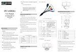
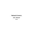
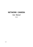
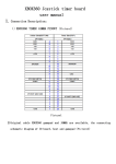
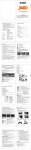
It may cause a malfunction. Picture 1 Cable function Never face the camera to strong light for long periods of time. It may damage the CMOS sensor. 1 ○ 2 ○ When this camera is installed near wireless co mmunication devices that emits strong electro magnetic field, irregularity such as noise may appear in the image. IP CAMERA 3.EQUIPMENT INSTALLATION User Manual IV-BUF363MP (MINI IR Bullet) V1.2 Picture 3 Equipment installation diagram(1) 1.OPEN-CASE INSPECTION List 2 Cable function of table 1.1 Check step When a user receives a IP camera, Please check the equipment appearance without obvious damage. Product NO. Name 1 Power Functional description DC12V power input packaging use protective material to deal with most accidental 2 impact in the transport process. LAN(RJ45) Please open the product outer packing,Check attachment Connect to a router or switch on your network using RJ45 Ethernet cable (Cat5e or better). 100Mhz connection. PoE supported (class 3 PoE switch required). provided product is complete,See List 1 below accessories package for inspection. 2.2 Dimensions 1.2 Standard accessories Please make sure the item is consistent with the listing Picture 2 Dimensions when open the product outer packing,Detailed list please see NO. Do not use the camera in extreme temperature condit the table below,Actual configuration, please refer to specific 1 IP Camera ions. products. 2 Mounting Screw 3 Expansion bolt 4 Sticker 5 Wall or Ceiling PRECAUTIONS Please use the camera within 14°F to 122°F List 1 Accessories list Air vent is required at high temperature Do not use or store the camera in humid environment Units Quantity IP camera pcs 1 User Manual pcs 1 Description: bracket installation metope, need to withstand at Inconsistent lighting or flickering may cause poor ima Accessory pack pcs 1 least 3X the total weight of the bracket and the camera ge. CD pcs 1 3.1 Put stickers to the surface where need to be installed (Wall It may cause poor image quality. Do not use the camera in unstable lighting conditions. Name Name Never use the camera close to gas or oil leak. or Ceiling) It may not operate properly. Do not disassemble the camera. There is no user serviceable part inside. Do not drop the camera or apply force on it. 3.2 Carried out in accordance with the installation sticker 2.PRODUCT STRUCTURE above marked the location of the hole; 2.1 Cable function 3.3 Open the accessory pack, take out expansion bolt, expansion bolt nail into drilled holes inside; 3.4 Open the attachment pack, take out the screws; With this 4.4 Go to CD->English->Software to find Upgrade Tool and screw will play good expansion bolt installation device fixed install it. and password, see below picture. 5.SPECIFICATIONS Model Picture 8 WEB GUI After login, enter into below picture IV-BUF363MP Camera to the surface (wall or ceiling); use the device ip address is in the same LAN of router, de Image Sensor 1/3” 3Megapixel Sony Aptina CMOS 3.5 Plug the external cables according to the use requirements 4.5 Run Upgrade Tool, Clock “IP Search”, you will find Effective Pixels 2048(H) x 1536(V) of equipment. the device ip, see below picture Scanning System Progressive Electronic Shutter Speed Auto/Manual 1/50~1/10000 Min. Illumination Color: 0. 1 lux /F1.4, B/W: 0.01 lux /F1.4,0 lux (IR on) S/N Ratio Picture 6 IP Configure >50dB Camera Features Picture 4 Equipment installation diagram(2) Max. IR LEDs Length Day/Night 4.9 Login with user name and password, see below picture Picture 9 Bit rate type 60 ft Auto(ICR) / Color / B/W Backlight BLC White Balance Auto Gain Control Auto/Manual Noise Reduction 3D Privacy Masking Up to 4 areas Slow Shutter None / Low / Middle / High Motion Detection 22 x 18 areas Lens Focal Length 3.6 Using tools to adjust screw loose device; 3.7 The up and down or so regulating equipment, according to the use requirements set equipment of direction; 3.6mm Max Aperture F1.2 Mount Type Board-in Type Compression H.264 High Profile / JPEG Snapshot Resolution 60Hz Mode: 3M (2048 x 1536) / 1080p (1920 × 1080) / 720P(1280 × 720) 4.6 Select the device to configure IP, see below picture Video Picture7 IP Configure 3.8 Using tools to screw locking device; Frame Rate 4.Network Operation 4.1 Use correct power supply Main Stream Sub Stream Bit Rate 4.2 After startup, connect the device with switch or router, Picture10 WEB GUI after login 3M (1 ~ 15fps) / 1080p / 720p (1~25/30fps) D1 / CIF (1 ~ 25/30fps) H.264: 50K ~ 8000Kbps Network Ethernet see below picture Protocol Picture 5 Network structure RJ-45 (10/100Base-T) IPv4, HTTP, SSL, TCP/IP, UDP, UPnP, ICMP, IGMP, SNMP, RTSP, RTP, SMTP, NTP, DHCP, DNS, PPPOE, DDNS, FTP, IP Filter, QoS, Cloud ONVIF ONVIF Ver. 2.0 Max. User Access 5 users Smart Phones iPhone, Android Browsers IE General Power Supply Power Consumption 4. 7 Default IP setting: IP address: 192.168.1.10 Subnet Mask: 255.255.255.0 refer to IP camera user manual in the CD “IPC Fast User Gateway: 192.168.1.1 Manual.pdf” and “IP Camera user manual Common User name: admin Password: no password 4.3 Make default IP address is 192.168.1.10 Equipment specific relevant parameter Settings please 4.8 Open IE type IP address. login with user name Version.pdf”. Working Environment DC12V, PoE (802.3af) <10W Temperature:14°F~140°F, Humidity: 10%~90% Ingress Protection IP66 Dimensions 2.31” x 2.5” x 5.75” Weight Appro 0.8 lbs The Specifications are subject to change without prior notice.