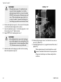
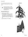
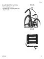
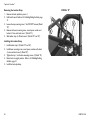
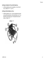
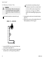
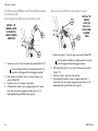
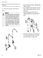
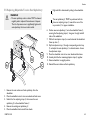
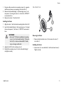
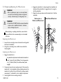
1
Top End® Crossfire™
Crossfire T6, Crossfire Titanium, Crossfire All Terrain
EN Crossfire series Wheelchair
User Manual
This manual MUST be given to the user of the product.
BEFORE using this product, read this manual and save for future reference.
©2013 Invacare®Corporation
All rights reserved. Republication, duplication or modification in whole or in part is prohibited without
prior written permission from Invacare. Trademarks are identified by ™and ®. All trademarks are
owned by or licensed to Invacare Corporation or its subsidiaries unless otherwise noted.
Shimano is a registered trademark of Shimano Inc.
Please record your serial number SN#__________________.
The SN is required for any warranty claims and placing aftermarket parts orders.
4.6
4.7
4.8
4.9
4.10
Contents
1
2
General . . . . . . . . . . . . . . . . . . . . . . . . . . . . . . . . . . . . . . 5
1.1
Symbols. . . . . . . . . . . . . . . . . . . . . . . . . . . . . . . . . . 5
1.2
Intended Use . . . . . . . . . . . . . . . . . . . . . . . . . . . . . . 5
1.3
Service Life . . . . . . . . . . . . . . . . . . . . . . . . . . . . . . . 5
1.4
Dealer/Technician Information . . . . . . . . . . . . . . . . . 5
Safety. . . . . . . . . . . . . . . . . . . . . . . . . . . . . . . . . . . . . . . .
2.1
Safety . . . . . . . . . . . . . . . . . . . . . . . . . . . . . . . . . . .
Safety/Handling of Wheelchairs . . . . . . . . . . . . . . .
2.2
Stability and Balance . . . . . . . . . . . . . . . . . . . . . . . . .
2.3
Reaching, Leaning and Bending . . . . . . . . . . . . . . . . .
2.4
Coping with Everyday Obstacles . . . . . . . . . . . . . . . .
2.5
A Note to Wheelchair Assistants . . . . . . . . . . . . . . .
2.6
Tipping . . . . . . . . . . . . . . . . . . . . . . . . . . . . . . . . . .
2.7
Stairways. . . . . . . . . . . . . . . . . . . . . . . . . . . . . . . . .
2.8
Escalators . . . . . . . . . . . . . . . . . . . . . . . . . . . . . . . .
2.9
Transferring To and From Other Seats . . . . . . . . . . .
2.10 Safety Inspection Checklist . . . . . . . . . . . . . . . . . . . .
6
6
9
10
12
13
13
13
13
14
14
15
3
Overview . . . . . . . . . . . . . . . . . . . . . . . . . . . . . . . . . . . . .
3.1
Label Locations . . . . . . . . . . . . . . . . . . . . . . . . . . . .
3.2
Typical Product Parameters . . . . . . . . . . . . . . . . . . .
3.3
Component Identification . . . . . . . . . . . . . . . . . . . . .
3.4
Tire Pressure Conversion. . . . . . . . . . . . . . . . . . . . .
17
17
18
27
28
4
Operation . . . . . . . . . . . . . . . . . . . . . . . . . . . . . . . . . . . .
4.1
Adjusting/Replacing Standard Footrest. . . . . . . . . . . .
4.2
Replacing/Adjusting Optional Adjustable Angle
Footrest . . . . . . . . . . . . . . . . . . . . . . . . . . . . . . . . .
4.3
Unfolding/Folding the Back . . . . . . . . . . . . . . . . . . . .
4.4
Back Angle Adjustment . . . . . . . . . . . . . . . . . . . . . .
4.5
Adjustable Tension Back Upholstery . . . . . . . . . . . . .
29
29
29
31
32
37
4.11
4.12
4.13
4.14
4.15
4.16
4.17
4.18
4.19
5
Back Height Adjustment . . . . . . . . . . . . . . . . . . .
Adjusting Quick-Release Axles . . . . . . . . . . . . . .
Adjusting Quad-Release Handles . . . . . . . . . . . . .
Removing Play from Rear Wheels . . . . . . . . . . . .
Adjusting Wheelbase Length, Adjusting Center of
Gravity (COG) . . . . . . . . . . . . . . . . . . . . . . . . .
Reposition the Camber Tube . . . . . . . . . . . . . . .
Repositioning the Camber Tube Clamp Socket
Screws . . . . . . . . . . . . . . . . . . . . . . . . . . . . . . .
Adjusting Wheelbase Width . . . . . . . . . . . . . . . .
Adjusting the Camber Tube . . . . . . . . . . . . . . . .
Determining/Setting Toe In/Toe Out . . . . . . . . . .
Adjusting Fork Tension . . . . . . . . . . . . . . . . . . .
Changing Wheel Lock Handle Position . . . . . . . .
Converting Wheel Lock From Push-to-Lock or
Pull-to-Lock. . . . . . . . . . . . . . . . . . . . . . . . . . . .
Adjusting/Replacing Anti-tipper . . . . . . . . . . . . . .
.
.
.
.
.
.
.
.
.
.
.
.
42
43
43
44
. . . 45
. . . 47
.
.
.
.
.
.
.
.
.
.
.
.
.
.
.
.
.
.
48
49
50
51
52
53
. . . 54
. . . 55
Service . . . . . . . . . . . . . . . . . . . . . . . . . . . . . . . . . . . . . . .
5.1
Installing the Swingaway Padded Armrest
Socket. . . . . . . . . . . . . . . . . . . . . . . . . . . . . . . . . . .
5.2
Installing/Removing/Adjusting the Swingaway
Padded Armrest. . . . . . . . . . . . . . . . . . . . . . . . . . . .
5.3
Removing/Installing Foldover Back Upholstery . . . . . .
5.4
Removing/Installing the Back Frame. . . . . . . . . . . . . .
5.5
Replacing Adjustable Tension Seat Upholstery . . . . . .
5.6
Replacing Screw-On Seat Upholstery Option . . . . . . .
5.7
Removing/Installing Rear Wheels. . . . . . . . . . . . . . . .
5.8
Replacing Quad-Release Axles . . . . . . . . . . . . . . . . .
5.9
Handrim Replacement . . . . . . . . . . . . . . . . . . . . . . .
5.10 Repairing/Replacing Rear Wheel, Tire/Tube . . . . . . . .
5.11 Removing/Installing the Camber Tube . . . . . . . . . . . .
5.12 Removing/Installing/Repositioning the Caster
Assemblies . . . . . . . . . . . . . . . . . . . . . . . . . . . . . . .
58
58
60
61
62
63
64
65
66
67
68
69
70
5.13
5.14
5.15
Removing/Installing the Fork Assembly . . . . . . . . . . . 72
Removing/Installing the Elastomers (Suspension
Forks Only) . . . . . . . . . . . . . . . . . . . . . . . . . . . . . . . 74
Replacing/Adjusting the Wheel Locks . . . . . . . . . . . . 75
6
Maintenance . . . . . . . . . . . . . . . . . . . . . . . . . . . . . . . . . .
6.1
Maintenance . . . . . . . . . . . . . . . . . . . . . . . . . . . . . .
Replacing/Repairing Rear Wheel Tire/Tube . . . . . .
Replacing/Repairing Caster Tire/Tube . . . . . . . . . .
76
76
76
77
7
Troubleshooting . . . . . . . . . . . . . . . . . . . . . . . . . . . . . . . 78
7.1
Troubleshooting . . . . . . . . . . . . . . . . . . . . . . . . . . . 78
8
Options . . . . . . . . . . . . . . . . . . . . . . . . . . . . . . . . . . . . . . 79
8.1
Options. . . . . . . . . . . . . . . . . . . . . . . . . . . . . . . . . . 79
9
Warranty. . . . . . . . . . . . . . . . . . . . . . . . . . . . . . . . . . . . . 84
9.1
Warranty Information . . . . . . . . . . . . . . . . . . . . . . . 84
9.2
Usability Survey . . . . . . . . . . . . . . . . . . . . . . . . . . . . 86
General
1 General
This product complies with Directive 93/42/EEC
concerning medical devices.
1.1 Symbols
The launch date of this product is stated in the EC
declaration of conformity.
Warnings
Signal words are used in this manual and apply to hazards or unsafe
practices which could result in personal injury or property damage.
See the information below for definitions of the signal words.
DANGER!
– Danger indicates an imminently hazardous situation
which, if not avoided, will result in death or serious
injury.
WARNING!
– Warning indicates a potentially hazardous situation
which, if not avoided, could result in death or serious
injury.
CAUTION!
– Caution indicates a potentially hazardous situation
which, if not avoided, may result in property damage
or minor injury or both.
1.2 Intended Use
The intended use for the manual (mechanical) wheelchair it to
provide mobility and transportation of physically impaired persons.
The manual wheelchair is intended for ongoing daily use. The models
offer a wide range of customization which allows for a better fit
for the end user resulting in comfort, lightweight, easier propelling,
transferring, and smooth ride. The manual wheelchair is intended for
indoor and outdoor use on firm surfaces free of climbing obstacles.
All other uses are prohibited.
1.3 Service Life
The expected service life of this product is five years when used daily
and in accordance with the safety instructions, maintenance intervals
and correct use, stated in this manual. The effective service life can
vary according to frequency and intensity of use.
1.4 Dealer/Technician Information
The term “qualified technician” in this manual refers to an Invacare
qualified technician or a Shimano® certified bicycle repair technician.
– Indicates a hazardous situation that could result in
damage to property if it is not avoided.
Gives useful tips, recommendations and information for
efficient, trouble-free use.
1134872-D~08
5
Top End® Crossfire™
2 Safety
2.1 Safety
The safety section contains important information for the safe operation and use of this product.
General Guidelines
WARNING!
– Do not use this product or any available optional equipment without first completely reading and understanding these instructions
and any additional instructional material such as owner’s manuals, service manuals or instruction sheets supplied with this product or
optional equipment. If you are unable to understand the warnings, cautions or instructions, contact a healthcare professional, dealer
or technical personnel before attempting to use this equipment - otherwise, injury or damage may occur.
WARNING!
ACCESSORIES
– Invacare products are specifically designed and manufactured for use in conjunction with Invacare accessories. Accessories designed
by other manufacturers have not been tested by Invacare and are not recommended for use with Invacare products.
– THE INFORMATION CONTAINED IN THIS DOCUMENT IS SUBJECT TO CHANGE WITHOUT NOTICE.
– Check all parts for shipping damage and test before using. In case of damage, do NOT use. Contact Invacare/Carrier for further
instruction.
WARNING!
Wheelchair User
– As a manufacturer of wheelchairs, Invacare endeavors to supply a wide variety of wheelchairs to meet many needs of the end user.
However, final selection of the type of wheelchair to be used by an individual rests solely with the user and his/her healthcare
professional capable of making such a selection.
6
1134872-D~08
Safety
WARNING!
Wheelchair Tie Down Restraints
– Invacare recommends that wheelchair users not be transported in vehicles of any kind while in wheelchairs. As of this date, the
Department of Transportation has not approved any tie-down systems for transportation of a user while in a wheelchair, in a
moving vehicle of any type.
– It is Invacare’s position that users of wheelchairs should be transferred into appropriate seating in vehicles for transportation and
use be made of the restraints made available by the auto industry. Invacare cannot and does not recommend any wheelchair
transportation systems.
Stability Warning
– The position of the footrest, camber tube (COG - Center of Gravity), seat angle, back angle, the tautness of the back upholstery
as well as the user's condition are directly related to the wheelchairs stability. Any change to one or any combination of the six
may cause the wheelchair to decrease in stability. Use EXTREME caution when using a new seating position. The addition of
anti-tippers may be required.
1134872-D~08
7
Top End® Crossfire™
When changes to the left hand column occur, follow across the chart and refer to the procedure to maintain the proper stability,
safety and handling of the wheelchair.
FOOTREST
POSITION
FOOTREST POSITION
=
=
CAMBER TUBE (COG)
BACK ANGLE
CAMBER TUBE
(COG)
ü
BACK UPHOLSTERY
BACK ANGLE
BACK
UPHOLSTERY
USER
CONDITION
SEAT ANGLE
ü
ü
ü
ü
ü
ü
=
ü
ü
ü
ü
=
ü
ü
USER CONDITION
ü
ü
ü
ü
=
ü
SEAT ANGLE
ü
ü
ü
ü
ü
=
WARNING!
Repair and Service Information
– Unless otherwise noted, all service and adjustments should be performed while the wheelchair is unoccupied.
Operating Information
– To determine and establish your particular safety limits, practice bending, reaching and transferring activities in several combinations
in the presence of a qualified healthcare professional before attempting active use of the wheelchair.
– DO NOT attempt to reach objects if you have to move forward in the seat.
– DO NOT attempt to reach objects if you have to pick them up from the floor by reaching down between your knees.
– DO NOT lean over the top of the back upholstery to reach objects from behind as this may cause the wheelchair to tip over.
– DO NOT shift your weight or sitting position toward the direction you are reaching as the wheelchair may tip over.
– DO NOT tip the wheelchair without assistance.
– DO NOT attempt to stop a moving wheelchair with wheel locks. Wheel locks are not brakes.
– Never leave an unoccupied wheelchair on an incline.
– DO NOT use an escalator to move a wheelchair between floors. Serious bodily injury may occur.
8
1134872-D~08
Safety
WARNING!
Operating Information
– DO NOT operate on roads, streets or highways.
– DO NOT climb, go up or down ramps or traverse slopes greater than 9°.
– DO NOT attempt to move up or down an incline with a water, ice or oil film.
– DO NOT attempt to ride over curbs or obstacles. Doing so may cause your wheelchair to turn over and cause bodily harm or
damage to the wheelchair.
– DO NOT attempt to lift the wheelchair by any removable (detachable) parts. Lifting by means of any removable (detachable) parts of
a wheelchair may result in injury to the user or damage to the wheelchair.
– DO NOT stand on the frame of the wheelchair.
– ALWAYS keep hands and fingers clear of moving parts to avoid injury.
Safety/Handling of Wheelchairs
“Safety and Handling” of the wheelchair requires the close attention of the wheelchair user as well as the assistant. This manual points out the most
common procedures and techniques involved in the safe operation and maintenance of the wheelchair. It is important to practice and master these
safe techniques until you are comfortable in maneuvering around the frequently encountered architectural barriers.
Use this information only as a “basic” guide. The techniques that are discussed on the following pages have been used successfully by many.
Individual wheelchair users often develop skills to deal with daily living activities that may differ from those described in this manual. Invacare
recognizes and encourages each individual to try what works best for him/her in overcoming architectural obstacles that they may encounter,
however, ALL WARNINGS and CAUTIONS given in this manual MUST be followed. Techniques in this manual are a starting point for the new
wheelchair user and assistant with “safety” as the most important consideration for all.
1134872-D~08
9
Top End® Crossfire™
2.2 Stability and Balance
WARNING!
– ALWAYS wear your seat positioning strap. Inasmuch as the seat positioning strap is an option on this wheelchair (you may order
with or without the seat positioning strap), Invacare strongly recommends ordering the seat positioning strap as an additional
safeguard for the wheelchair user. The seat positioning strap is a positioning strap only. It is not designed for use as a safety device
withstanding high stress loads such as auto or aircraft safety belts. If signs of wear appear, strap MUST be replaced IMMEDIATELY.
– DO NOT attempt to lift a wheelchair by lifting on any removable (detachable) parts. Lifting by means of any removable (detachable)
parts of the wheelchair may result in injury to the user or damage to the wheelchair.
– ALWAYS check hand grips for looseness before using the wheelchair. If loose and/or worn, replace IMMEDIATELY.
– Anti-tippers MUST be attached at all times. Inasmuch as the anti-tippers are an option on this wheelchair (you may order with or
without the anti-tippers), Invacare strongly recommends ordering the anti-tippers as an additional safeguard for the wheelchair user.
– DO NOT climb, go up, or down ramps or traverse slopes greater than 9°.
– Invacare strongly recommends proceeding down ramps or slopes slowly to avoid hard braking or sudden stops.
WARNING!
– Be aware that carrying heavy objects on your lap while occupying the wheelchair may adversely affect the stability of the wheelchair,
resulting in serious bodily injury to the user, damage to the wheelchair and surrounding property.
– This wheelchair has been designed to accommodate one individual. If more than one individual occupies the wheelchair this
may adversely affect the stability of the wheelchair, resulting in serious bodily injury to the user and passenger and damage the
wheelchair and surrounding property.
To assure stability and proper operation of your wheelchair, you MUST at all times maintain proper balance. Your wheelchair has been designed to
remain upright and stable during normal daily activities as long as you DO NOT move beyond the center of gravity.
Virtually all activities which involve movement in the wheelchair have an effect on the center of gravity. Invacare recommends using seat positioning
straps for additional safety while involved in activities that shift your weight.
DO NOT lean forward out of the wheelchair any further than stability will allow. Make sure casters are pointing in the forward position whenever
you lean forward. This can be achieved by advancing the wheelchair and then reversing it in a straight line.
10
1134872-D~08
Safety
WARNING!
– DO NOT attempt to reach objects if you have to move forward in the seat or pick them up from the floor by reaching down
between your knees.
– The position of the footrest, camber tube, back angle, the tautness of the back upholstery as well as the user's condition are directly
related to the wheelchair's stability. Any change to one or any combination of the five may cause the wheelchair to decrease in
stability. Use EXTREME caution when using a new seating position. The addition of anti-tippers may be required.
Many activities require the wheelchair owner to reach, bend and transfer in and out of the wheelchair. These movements will cause a change
to the normal balance, the center of gravity, and the weight distribution of the wheelchair.
To determine and establish your particular safety limits, practice bending, reaching and transferring activities in several combinations in the presence
of a qualified health-care professional before attempting active use of wheelchair.
Proper positioning is essential for your safety. When reaching, leaning, bending forward, it is important to use the front casters as a tool to
maintain stability and balance.
•
•
Lengthening the wheelbase A will increase the stability and maintain standard maneuverability of wheelchair.
Shortening the wheelbase B will decrease the stability, increase the maneuverability and distribute additional weight onto the rear wheels.
1134872-D~08
11
Top End® Crossfire™
2.3 Reaching, Leaning and Bending
Reaching, Leaning, or Bending Forward
WARNING!
– DO NOT attempt to reach objects if you have to
move forward in the seat.
– DO NOT attempt to reach objects if you have to pick
them up from the floor by reaching down between
your knees.
– DO NOT lean over the top of the back upholstery
to reach objects from behind as this may cause the
wheelchair to tip over.
– DO NOT shift your weight or sitting position toward
the direction you are reaching as the wheelchair may
tip over.
Position the front casters so that they are extended as far forward as
possible and engage wheel locks..
Reaching, Leaning, or Bending Backwards
Position wheelchair as close as possible to the desired object. Point
front casters forward to create the longest possible wheelbase.
12
1134872-D~08
Safety
Reach back only as far as your arm will extend without changing
your sitting position.
2.4 Coping with Everyday Obstacles
Coping with the irritation of everyday obstacles can be alleviated
somewhat by learning how to manage your wheelchair. Keep in mind
your center of gravity to maintain stability and balance.
2.5 A Note to Wheelchair Assistants
When assistance to the wheelchair user is required, remember to
use good body mechanics. Keep your back straight and bend your
knees whenever tilting the wheelchair or traversing curbs, or other
impediments.
WARNING!
– Do not attempt to lift a wheelchair by lifting on any
removable (detachable) parts. Lifting by means of
any removable (detachable) parts of a wheelchair
may result in injury to the user or damage to the
wheelchair.
Also, be aware of any removable (detachable) parts. These MUST
NEVER be used to move the wheelchair or as lifting supports, as
they may be inadvertently released, resulting in possible injury to the
user and/or assistant(s).
2.6 Tipping
WARNING!
– DO NOT tip the wheelchair without assistance.
– When lowering the front casters of the wheelchair,
DO NOT let the wheelchair drop the last few inches
to the ground. This could result in injury to the
occupant.
After mastering the techniques of tipping the wheelchair, use one of
the following methods to tackle curbs, short stairs, etc.
2.7 Stairways
WARNING!
– Extreme caution is advised when it is necessary to
move an occupied or unoccupied wheelchair up
or down the stairs. Invacare recommends that, if
possible, the user be removed from the wheelchair
prior to moving. Invacare recommends using two
assistants and making thorough preparations. Make
sure to use only secure, non-detachable parts for
hand-held supports.
Follow this procedure for moving the wheelchair between floors
when an elevator is not available:
When learning a new assistance technique, have an experienced
assistant help you before attempting it alone.
1134872-D~08
13
Top End® Crossfire™
Moving Up Stairs
1.
2.
3.
4.
5.
6.
If necessary, rotate the anti-tippers so the wheels are facing up.
One assistant (positioned behind the wheelchair), securely grasps
a non-removable (non-detachable) part of the wheelchair for
leverage and tilts the wheelchair back to the balance point.
After the wheelchair has been tilted back to the balance point,
the assistant behind the wheelchair backs the wheelchair up
against the first step.
The second assistant (positioned in the front of the wheelchair),
with a firm hold on a non-detachable part of the framework, lifts
the wheelchair up and on to the next stair above and steadies
the wheelchair as the assistant behind the wheelchair places one
foot on the next stair above and repeats process.
The wheelchair should not be lowered until the last stair has
been negotiated and the wheelchair has been rolled away from
the stairway.
If necessary, rotate the anti-tippers so the wheels are facing
down.
3.
4.
5.
6.
After the wheelchair has been tilted back to the balance point,
the assistant behind the wheelchair rolls the wheelchair up to
the edge of the first step.
The second assistant (positioned in the front of the wheelchair),
with a firm hold on a non-detachable part of the framework,
lowers the wheelchair down and on to the next stair below and
steadies the wheelchair as the assistant in the rear places one
foot on the next stair below and repeats process.
The wheelchair should not be lowered until the last stair has
been negotiated and the wheelchair has been rolled away from
the stairway.
If necessary, rotate the anti-tippers so the wheels are facing
down.
2.8 Escalators
WARNING!
– DO NOT use an escalator to move a wheelchair
between floors. Serious bodily injury may occur.
2.9 Transferring To and From Other Seats
Moving Down Stairs
1.
2.
14
If necessary, rotate the anti-tippers so the wheels are facing up.
One assistant (positioned behind the wheelchair), securely grasps
a non-removable (non-detachable) part of the wheelchair for
leverage and tilts the wheelchair back to the balance point.
WARNING!
– Before attempting to transfer in or out of the
wheelchair, every precaution should be taken to
reduce the gap distance.
– Turn both casters parallel to the object you are
transferring onto. Also be certain the wheel locks are
engaged to help prevent the wheels from moving.
– When transferring, position yourself as far back
as possible in the seat. This will prevent damaged
upholstery and the possibility of the wheelchair tipping
forward.
1134872-D~08
Safety
This activity may be performed independently provided you
have adequate mobility and upper body strength.
CAUTION!
– As with any vehicle, the wheels and tires should be
checked periodically for cracks and wear, and should
be replaced if damaged.
Initial adjustments should be made to suit your personal body
structure and preference. Thereafter follow these maintenance
procedures:
Inspect Initially
q Ensure wheelchair rolls straight (no excessive drag/pull to one
Position the wheelchair as close as possible along side the seat to
which you are transferring, with the front casters parallel to it.
Remove the armrest, if installed. Engage wheel locks. Shift body
weight into seat with transfer.
During independent transfer, little or no seat platform will be beneath
you. Use a transfer board if at all possible.
2.10 Safety Inspection Checklist
Every six months, take your wheelchair to a qualified
technician for a thorough inspection and servicing. Regular
cleaning will reveal loose or worn parts and enhance the
smooth operation of your wheelchair. To operate properly
and safely, your wheelchair MUST be cared for just like any
other vehicle. Routine maintenance will extend the life and
efficiency of your wheelchair. Clean upholstery with mild
soap and water or spray disinfectant using a sponge. DO
NOT use bleach or wash in a washing machine.
1134872-D~08
side).
q Ensure wheel locks Do not interfere with tires when rolling.
q Ensure pivot points are free of wear and looseness.
q Ensure wheel locks are easy to engage and prevent the wheels
q
q
q
q
q
q
q
q
q
q
q
q
q
from moving.
Ensure that the casters are free of debris.
Inspect seat and back upholstery for rips or sagging.
Inspect upholstery fastening flaps to ensure they securely latch.
Inspect seat positioning strap for any signs of wear. Ensure
buckle latches. Verify hardware that attaches strap to frame is
secure and undamaged. Replace if necessary.
Ensure hand grips (if equipped) are not loose.
Ensure quick release axles and camber inserts are clean.
Ensure camber bar mounting clamps are securely tightened.
Ensure quick/quad release axles lock properly.
Ensure no excessive side movement or binding when lifted and
spun.
Inspect handrims for signs of rough edges or peeling.
Inspect spokes for bent or broken spokes.
Ensure all spokes are uniformly tight.
Clean upholstery and armrests.
15
Top End® Crossfire™
q Inspect wheel/fork assembly for proper tension by spinning
q
q
q
q
q
caster; caster should come to a gradual stop.
Loosen/tighten locknut if wheel wobbles noticeably or binds
to a stop.
Ensure wheel bearings are clean and free of moisture.
Inspect tires for flat spots and wear.
If pneumatic tires check for proper inflation.
Check that all labels are present and legible. Replace if necessary.
Inspect/Adjust Weekly
q Ensure wheel locks are easy to engage and prevent the wheels
q
q
q
q
q
q
q
q
q
q
from moving.
Ensure that the casters are free of debris.
Ensure hand grips (if equipped) are not loose.
Ensure quick release axles and camber inserts are clean.
Ensure quick/quad release axles lock properly.
Inspect handrims for signs of rough edges or peeling.
Inspect spokes for bent or broken spokes.
Ensure all spokes uniformly tight.
Inspect wheel/fork assembly for proper tension by spinning
caster; caster should come to a gradual stop.
Inspect tires for flat spots and wear.
If pneumatic tires check for proper inflation.
q Loosen/tighten locknut if wheel wobbles noticeably or binds
to a stop.
q Ensure wheel bearings are clean and free of moisture.
Inspect/Adjust Periodically
q Ensure wheelchair rolls straight (no excessive drag/pull to one
q
q
q
q
q
q
q
q
q
side).
Ensure wheel locks are easy to engage.
Ensure that the casters are free of debris.
Inspect seat and back upholstery for rips or sagging.
Ensure camber bar mounting clamps are securely tightened.
Ensure no excessive side movement or binding when lifted and
spun.
Inspect handrims for signs of rough edges or peeling.
Clean upholstery and armrests.
Ensure wheel bearings are clean and free of moisture.
Check that all labels are present and legible. Replace if necessary.
Inspect /Adjust Monthly
q
q
q
q
q
q
16
Ensure wheel locks Do not interfere with tires when rolling.
Ensure that the casters are free of debris.
Ensure pivot points are free of wear and looseness.
Inspect upholstery fastening flaps to ensure they securely latch.
Inspect seat positioning strap for any signs of wear. Ensure
buckle latches. Verify hardware that attaches strap to frame is
secure and undamaged. Replace if necessary.
Ensure camber bar mounting clamps are securely tightened.
1134872-D~08
Overview
3 Overview
3.1 Label Locations
1134872-D~08
17
Top End® Crossfire™
3.2 Typical Product Parameters
All specifications are approximate.
Crossfire T6
FRAME:
6061T6 Aluminum
FRONT FRAME:
Tapered front end (Standard), V-Style (Optional)
FRONT FRAME ANGLE:
70°, 75°, 80°, 85° or 90°
FOOTREST:
Tubular footrest in same material as frame (Standard),
Adjustable Angle NCO, Plastic or Carbon Fiber Cover (Optional)
SEAT HEIGHT
FRONT:
16 to 21 inches (40.6 to 53.3 cm) (Fixed)
REAR:
14 to 20 Inches (35.6 to 50.8 cm) (Fixed), Ergo Level Seat (Optional)
ARMS (OPTIONAL):
Swing-away Style
SIDE GUARDS (OPTIONAL)
FOLDING BACK:
Removable, Folding, Removable with Fender
FIXED BACK:
Fixed Aluminum, Fixed Carbon Fiber
SEAT WIDTH:
12 to 18 inches (30.5 to 45.7 cm) (Standard), 19 to 20 inches (48.3 to
50.8 cm) (Optional), Tapered Seat Width (Optional)
18
1134872-D~08
Overview
Crossfire T6
SEAT DEPTH:
14 to 18 inches (35.6 to 45.7 cm) (Standard), 19 to 20 inches (48.3 to
50.8 cm) (Optional)
BACK STYLE:
Folding (Standard), Fixed (Optional)
BACK HEIGHT
ADJUSTABLE:
9 to 11, 10 to 14, 12 to 16, 14 to 18, or 16 to 20 inches
(20.32 to 27.94, 25.4 to 35.56, 30.48 to 40.64, 35.56 to 45.72, 40.64
to 50.8 cm)
FIXED:
Not Available
BACK ANGLE
FOLDING:
-8°, -4°, 0° and +4°,+8°
FIXED:
Not Available
BACK UPHOLSTERY:
U850 Black - Adjustable Tension by Straps
SEAT UPHOLSTERY:
U850 Black - Adjustable Tension by Straps
AXLE POSITIONS/CENTER OF GRAVITY:
Adjustable to 4¼ inches (10.8 cm) in two positions:
Amputee Position: -2¼ to 2 inches (-5.7 to 5.1 cm)
Active Position: 1¼ to 5½ inches (3.2 to 14 cm)
REAR WHEEL AXLE:
Quick Release (Standard), Quad-Release or Titanium (Optional)
REAR WHEEL CAMBER
CAMBER TUBE:
0°, 3°, 6°, or 9°
REAR WHEELS
REAR WHEEL TYPE:
1134872-D~08
Sun High performance (Standard), Spinergy SPOX, Spinergy LX, Sun
Fusion
19
Top End® Crossfire™
REAR WHEEL SIZE:
22, 24 or 25-inch (55.9, 61 or 63.5 cm) (Standard), 26-inch (66 cm)
(Optional)
TIRES:
1" Primo High pressure clincher (standard),1" Kenda, 1" Schwalbe flat
resistant, 1 3/8" treaded, 1 3/8" w/flat free inserts, 1" solid, 2" knobby
HANDRIMS:
Aluminum Anodized (Standard)
Titanium, Coated, Natural Fit® (Optional)
WHEEL LOCKS:
Push or Pull to Lock (Standard) or Hideaway Undermount (Optional)
FRONT FORKS:
Non-Suspension (Standard), Suspension (Optional)
CASTERS
CASTER SIZE:
3, 4 or 5-inch (7.6, 10.2 or 12.7 cm)
CASTER TYPE:
Semi-pneumatic (Standard), Soft Roll or Lighted (Optional)
ANTI-TIPPERS:
Optional
WEIGHT:
19.5 lbs (8.8 kg)
SHIPPING WEIGHT:
30 lbs (14 kg)
WEIGHT LIMITATION:
250 lbs (114 kg)
16 x 16-inch seat, rear wheels and minimal options are
included in the weight.
20
1134872-D~08
Overview
All specifications are approximate.
Crossfire Titanium
FRAME:
Grade 9 Titanium
FRONT FRAME:
Tapered front end (Standard), V-Style (Optional)
FRONT FRAME ANGLE:
70°, 75°, 80°, 85° or 90°
FOOTREST:
Tubular footrest in same material as frame (Standard), Adjustable Angle
NCO, Plastic or Carbon Fiber Cover (Optional)
SEAT HEIGHT
FRONT:
16 to 21 inches (40.6 to 53.3 cm) (Fixed)
REAR:
14 to 20 Inches (35.6 to 50.8 cm) (Fixed), Ergo Level Seat (Optional)
ARMS (OPTIONAL):
Swing-away Style
SIDE GUARDS (OPTIONAL)
FOLDING BACK:
Removable, Folding, Removable with Fender
FIXED BACK:
Fixed Aluminum, Fixed Carbon Fiber
SEAT WIDTH:
12 to 18 inches (30.5 to 45.7 cm) (Standard), 19 to 20 inches (48.3 to
50.8 cm) (Optional), Tapered Seat Width (Optional)
1134872-D~08
21
Top End® Crossfire™
Crossfire Titanium
SEAT DEPTH:
14 to 18 inches (35.6 to 45.7 cm) (Standard), 19 to 20 inches (48.3 to
50.8 cm) (Optional)
BACK STYLE:
Folding (Standard), Fixed (Optional)
BACK HEIGHT
ADJUSTABLE:
8 to 11, 10 to 14, 12 to 16, 14 to 18, or 16 to 20 inches
(20.32 to 27.94, 25.4 to 35.56, 30.48 to 40.64, 35.56 to 45.72, 40.64
to 50.8 cm)
FIXED:
8 to 16 inches (20.32 to 40.64 cm)
BACK ANGLE
FOLDING:
-8°, -4°, 0° and +4°,+8°
FIXED:
0°, 3°, 6°, and 9°
BACK UPHOLSTERY:
U850 Black - Adjustable Tension by Straps
SEAT UPHOLSTERY:
U850 Black - Adjustable Tension by Straps
AXLE POSITIONS/CENTER OF GRAVITY:
Adjustable to 4¼ inches (10.8 cm) in two positions:
Amputee Position: -2¼ to 2 inches (-5.7 to 5.1 cm)
Active Position: 1¼ to 5½ inches (3.2 to 14 cm)
REAR WHEEL AXLE:
Quick Release (Standard), Quad-Release or Titanium (Optional)
REAR WHEEL CAMBER
CAMBER TUBE:
22
0°, 3°, 6°, or 9°
1134872-D~08
Overview
Crossfire Titanium
REAR WHEELS
REAR WHEEL TYPE:
Sun High performance (Standard), Spinergy SPOX, Spinergy LX, Sun
Fusion
REAR WHEEL SIZE:
22, 24 or 25-inch (55.9, 61 or 63.5 cm) (Standard), 26-inch (66 cm)
(Optional)
TIRES:
1" Primo High pressure clincher (standard),1" Kenda, 1" Schwalbe flat
resistant, 1 3/8" treaded, 1 3/8" w/flat free inserts, 1" solid, 2" knobby
HANDRIMS:
Aluminum Anodized (Standard), Titanium, Coated, Natural Fit®
(Optional)
WHEEL LOCKS:
Push to Lock (Standard) or Hideaway Undermount (Optional)
FRONT FORKS:
Non-Suspension (Standard), Suspension (Optional)
CASTERS
CASTER SIZE:
3, 4 or 5 inch (7.6, 10.2 or 12.7 cm)
CASTER TYPE:
Semi-pneumatic (Standard), Soft Roll or Lighted (Optional)
ANTI-TIPPERS:
Optional
WEIGHT:
18.5 lbs (8.3 kg)
SHIPPING WEIGHT:
30 lbs (14 kg)
WEIGHT LIMITATION:
250 lbs (114 kg)
16 x 16-inch seat, rear wheels and minimal options are
included in the weight.
1134872-D~08
23
Top End® Crossfire™
All specifications are approximate.
Crossfire All Terrain
FRAME:
6061T6 Aluminum
FRONT FRAME:
Tapered front end (Standard)
FRONT FRAME ANGLE:
90°
FOOTREST:
Adjustable Angle Footplate (Standard), 2 inch risers (Optional)
SEAT HEIGHT:
Front: 19 to 21 inches (48.26 to 53.34 cm) (Fixed)
Rear: 15** to 20 Inches (38.10 to 50.8 cm) (Fixed)
ARMS (OPTIONAL):
Swing-away Style
SIDE GUARDS (OPTIONAL)
FOLDING BACK:
Removable, Folding, Removable with Fender
FIXED BACK:
Fixed Aluminum, Fixed Carbon Fiber
SEAT WIDTH:
14 to 18 inches (30.48 to 45.72 cm) (Standard), 19 to 20 inches (48.26
to 50.8 cm ) (Optional)
SEAT DEPTH:
14 to 18 inches (35.56 to 45.72 cm) (Standard), 19 to 20 inches (48.26
to 50.8 cm) (Optional)
BACK STYLE:
Folding (Standard), Fixed (Optional)
BACK HEIGHT:
No fixed height available.
ADJUSTABLE:
9 to 11, 10 to 14, 12 to 16, 14 to 18, or 16 to 20 inches
(20.32 to 27.94, 25.4 to 35.56, 30.48 to 40.64, 35.56 to 45.72, 40.64
to 50.8 cm)
FIXED:
24
8 to 16 inches (20.32 to 40.64)
1134872-D~08
Overview
BACK ANGLE
FOLDING:
-15°, -10°, -5°, 0° and 5°
FIXED:
0°, 3°, 6°, and 9°
BACK UPHOLSTERY:
U850 Black - Adjustable Tension by Straps
SEAT UPHOLSTERY:
U850 Black - Adjustable Tension by Straps
AXLE POSITIONS/CENTER OF GRAVITY:
Adjustable to 4¼ inches (10.8 cm) in two positions:
Amputee Position: -2¼ to 2 inches (-5.72 to 5.08 cm)
Active Position: 1¼ to 5½ inches (3.18 to 13.97 cm)
REAR WHEEL AXLE:
Quick Release (Standard), Quad-Release or Titanium (Optional)
REAR WHEEL CAMBER
CAMBER TUBE:
0°, 3°, 6°, or 9°
REAR WHEELS*
REAR WHEEL TYPE:
High Performance with Knobby tires (Standard) Spinergy® Spox
(Optional)
REAR WHEEL SIZE:
24 inch (60.96) or 25 inch (63.5 cm)
HANDRIMS:
Aluminum Anodized (Standard)
Titanium, Coated, Natural Fit® (Optional)
WHEEL LOCKS:
Push to Lock (Optional)
FRONT FORKS:
Non-Suspension
CASTERS
CASTER SIZE:
8 inch (20.3 cm)
CASTER TYPE:
Pneumatic (Standard)
1134872-D~08
25
Top End® Crossfire™
ANTI-TIPPERS:
Optional
WEIGHT:
30 lbs (14 Kg)
SHIPPING WEIGHT:
30 lbs (14 kg)
WEIGHT LIMITATION:
250 lbs (114 kg)
16 x 16 inches (40.64 x 40.64 cm) seat, rear wheels and
minimal options are included in the weight.
*Refer to 3.1 Label Locations, page 17
** 15 inch (38.1 cm) rear seat height only available with 24
inch (60.7 cm) rear wheels.
26
1134872-D~08
Overview
3.3 Component Identification
Crossfire T7A is shown. The other chairs in the Crossfire
Series have similar components.
1134872-D~08
27
Top End® Crossfire™
3.4 Tire Pressure Conversion
If equipped with high pressure tires a Presta valve adaptor
will be needed to inflate the tires to the recommended
pressures below.
PSI rating is printed on the side of the tire.
Conversion formula: 1 psi = 6.895 kPa (approx. 7 kPa).
28
PSI
KILOPASCALS
PSI
KILOPASCALS
50
345
90
621
55
379
95
655
60
414
100
690
65
448
105
724
70
483
110
758
75
517
115
793
80
552
120
827
85
586
1134872-D~08
Operation
4 Operation
4.1 Adjusting/Replacing Standard Footrest
WARNING!
– After any adjustments, repair or service and before
use, make sure all attaching hardware is tightened
securely - otherwise injury or damage may occur.
– ALWAYS perform this procedure in the presence of
an assistant. The position of the footrest, camber
tube, seat angle, back angle, the tautness of the back
upholstery as well as the user's condition are directly
related to the wheelchairs stability. Any change to
one or any combination of the five may cause the
wheelchair to decrease in stability. Use EXTREME
caution when using a new seating position. The
addition of anti-tippers may be required.
– Check ALL allen screws that secure the footrest/raised
footrest system to the wheelchair frame to make
sure they are securely tightened BEFORE using the
wheelchair. ESPECIALLY if engaging in ANY contact
sport.
– The footrest assembly MUST be at least 1¾-inches
above the ground/floor to avoid hitting protruding
objects when using this wheelchair.
1.
Loosen the allen screw of the two clamps A that secure the
footrest B to the wheelchair frame C.
Replacing the Footrest
1.
2.
Remove existing footrest.
Install new footrest B.
1134872-D~08
WARNING!
– The standard footrest has an open hoop. A footplate
cover is recommended for wheelchair users that have
leg spasticity or whose feet have a possibility of falling
through the footrest hoop. A calf strap is provided
with each wheelchair to prevent the feet from slipping
backwards off of the footrest. Be sure the calf strap is
secure when using the wheelchair.
Adjusting the Footrest
1.
2.
Position new/existing footrest B to desired height.
Tighten the allen screw of the two clamps A that secure the
footrest B to the wheelchair frame C.
4.2 Replacing/Adjusting Optional Adjustable
Angle Footrest
A footrest for short leg lengths is available as an option. It
has an adjustable footplate with 2 inch spacers and longer
mounting screws that attach the footrest to the footrest
tube.
29
Top End® Crossfire™
Replacing the Footrest
The locknuts should lie in the channel of the footplate
clamp.
Adjusting Footplate Depth
1.
Remove the two mounting screws E and locknuts (not shown)
that secure the footplate D to the footrest tubes C.
Observe the angle of footplate D for reinstallation.
2.
3.
Move the footplate D to one of two mounting positions F to
accommodate the user.
Using the two mounting screws E and locknuts, secure the
footplate D to the footrest tubes C.
The locknuts should lie in the channel of the footplate
half clamp.
1.
2.
3.
4.
5.
Loosen, but do not remove the allen screw of the two clamps A
that secure the footrest to the wheelchair frame B.
Slide the existing footrest tubes C out of the wheelchair frame
B and install new footrest by reversing this step.
Position the new footrest to a determined height.
Tighten the allen screw of the two clamps A that secure the
footrest to the wheelchair frame B.
Adjust the footplate D to the desired position.
Adjusting Footplate Angle
1.
2.
3.
30
Loosen, but DO NOT remove the two mounting screws E and
locknuts (not shown) that secure the footplate D to the two
footrest tubes C.
Position the footplate D to the necessary angle to accommodate
the user.
Retighten the two mounting screws E and locknuts.
1134872-D~08
Operation
4.3 Unfolding/Folding the Back
DETAIL “A” — FOLDING THE BACK
WARNING!
– ALWAYS perform these procedures in the presence
of an assistant. The position of the footrest, camber
tube, seat angle, back angle, the tautness of the back
upholstery as well as the user's condition are directly
related to the wheelchairs stability. Any change to
one or any combination of the five may cause the
wheelchair to decrease in stability. Use EXTREME
caution when using a new seating position. The
addition of anti-tippers may be required.
– After ANY adjustments, repair or service and BEFORE
use, make sure all attaching hardware is tightened
securely - otherwise injury or damage may occur.
WARNING!
– After unfolding the back, ensure that the plunger
pins are fully engaged in the mounting holes of the
adjustment square in the back cane mounting brackets
(Detail “A”). Back MUST be locked securely in place.
Otherwise, serious injury could result.
1.
2.
To fold the back A, pull up on the back release cord B and push
the back A toward the seat C of the wheelchair (Detail “A”).
To unfold the back A, pull up on the back release cord B and
lift the back A away from the seat C until the back locks into
place (Detail “B” and Detail “C”).
An audible “click” will be heard when the plunger pins fully
engage into the adjustment square A (Detail “C”) and the
split ring will be flush up against the back stop insert.
The back should have a small amount of movement when
locked in the open position. Plunger pins should snap in and
release easily without resistance.
1134872-D~08
31
Top End® Crossfire™
DETAIL “B” — UNFOLDING THE BACK
4.4 Back Angle Adjustment
The numbers in the recess of the back angle plate are
intended to define the resulting back angle of a chair that
has 2 inch (5.08 cm) seat drop [at 17 inch (43.18)depth]
and that is measured relative to true vertical with the chair
sitting on a level surface. The plus (+) sign increases the back
angle and the minus (-) sign decreases the back angle. The
resulting back angle will vary somewhat depending on your
chair configuration. Refer to chart to see these settings
converted into back angle relative to the seat.
Perform this procedure on both sides of the wheelchair at
the same time.
DETAIL “C”
32
DETAIL “A”
1134872-D~08
Operation
1.
2.
Fold down the back. Refer to 4.3 Unfolding/Folding the Back,
page 31.
Loosen the jam nut A on the placement screw B located at the
bottom of the back cane C (Detail “A”).
DETAIL “C”
DETAIL “B”
4.
5.
3.
Tighten the placement screw B so that the screw and jam nut A
are snug against the bottom of the back cane C (Detail “B”).
1134872-D~08
Remove the mounting screw D that secures the adjustment
square E to the back angle plate F (Details “A” and “C”).
Remove the adjustment square E from the recess of the back
angle plate F (Detail “C”).
Note the hole on the adjustment square. When the hole
is positioned on top of the number inside the recess,
this number represents the back angle relative to true
vertical. One side of the adjustment square provides
back angles of -8°, 0° and -4°. Flip the adjustment square
over to obtain back angles of 8°, 4° and 0° .
33
Top End® Crossfire™
WARNING!
– If the adjustment square E is installed into the
recess of the back angle plate F so that the
adjustment square hole is not on top of a number,
DO NOT use this position. Otherwise, injury will
occur. When the adjustment square hole is not
on top of a number, it prevents the locking pins
from locking into position when the back is raised.
6.
7.
8.
Position the adjustment square E in the recess of the back plate
G with the hole located aligned with a number .
Secure the adjustment square E to the back angle plate F with
the mounting screw D. Tighten securely.
Repeat STEPS 2-6 for remaining back cane C.
WARNING!
– After unfolding the back, ensure that the plunger
pins are fully engaged in the mounting holes of the
adjustment square in the back angle plates (Detail
“A”). Otherwise, serious injury could result.
9.
34
DETAIL “D”
Unfold the back until the plunger pins lock into the mounting
holes in the adjustment square G.
10. Unthread the placement screw B until head of screw rests on
seat rail H (Detail “D”).
11. Completely tighten jam nut A up against bottom of back cane C
(Detail “D”).
When adjusted properly, the back should have a small
amount of movement when locked in the open position.
Plunger pins should snap in and release easily without
resistance.
1134872-D~08
Operation
DESIRED SEAT ANGLE
ADJUSTMENT SQUARE POSITION
NUMERICAL
-8°
Hole in adjustment square will
align with 8– when installed in this
orientation.
-4°
Hole in adjustment square will
align with 4– when installed in this
orientation.
0°
1134872-D~08
GRAPHICAL
OPTION 1
Hole in adjustment square
will align with 0° when
installed in this orientation.
OPTION 2
35
Top End® Crossfire™
+4°
+8°
36
Hole in adjustment square will
align with 4+ when installed in
this orientation.
Hole in adjustment square
will align with 8+ when
installed in this orientation.
1134872-D~08
Operation
4.5 Adjustable Tension Back Upholstery
WARNING!
– ALWAYS perform these procedures in the presence
of an assistant. The position of the footrest, camber
tube, seat angle, back angle, the tautness of the back
upholstery as well as the user's condition are directly
related to the wheelchairs stability. Any change to
one or any combination of the five may cause the
wheelchair to decrease in stability. Use EXTREME
caution when using a new seating position. The
addition of anti-tippers may be required.
Adjusting the Tautness of the Back
– The adjustable tension back upholstery consists of an
upper and lower (lumbar) section.
To adjust the back tension, perform the following:
1.
2.
Lift back upholstery cover up and flip over toward front of
wheelchair.
Tighten or loosen the adjuster fastening straps A.
The Back Upholstery Cover
The back upholstery cover is designed for three
reasons:
– The first is as a modesty cover.
– The second is to keep the cushion from sliding out of
the back of the wheelchair.
– The third is a sacral support depending upon how far
or tight the flap is pulled under the seat cushion.
– The adjuster fastening straps can be adjusted at various
levels of tension to accommodate individual end-users.
1134872-D~08
37
Top End® Crossfire™
Removing/Installing the Back Upholstery Cover,
Adjustable Tension Back Upholstery and Lumbar
Strap
DETAIL “A”
– If replacing the back upholstery cover, adjustable
tension back upholstery and/or lumbar strap, remove
the existing upholstery/lumbar strap and install the
new upholstery/lumbar strap.
Removing the Back Upholstery Cover
1.
2.
3.
38
Remove the seat cushion, if applicable.
Pull the back upholstery cover A away from the adjustable
tension back upholstery B separating the fastening strips of
the back upholstery cover C from the fastening strips of the
adjustable tension back upholstery and seat D (Details “A” and
“B”).
Remove back upholstery cover A from wheelchair.
DETAIL “B”
1134872-D~08
Operation
Removing the Adjustable Tension Back Upholstery
1.
2.
DETAIL “C”
Remove the back upholstery cover A.
Slide adjustable tension back upholstery B off back canes E
(Details “C” and “D”).
DETAIL “D”
1134872-D~08
39
Top End® Crossfire™
Removing the Lumbar Strap
1.
2.
3.
4.
5.
DETAIL “E”
Remove the back upholstery cover A.
Fold back forward. Refer to 4.3 Unfolding/Folding the Back, page
31.
Loosen the top mounting screw F but DO NOT remove (Detail
“E”).
Remove the lower mounting screw, coved spacer, washer and
locknut G from each back cane E (Detail “E”).
Slide lumbar strap H off back canes E (Details “D” and “E”).
Installing the Lumbar Strap
1.
2.
3.
4.
5.
40
Install lumbar strap H (Details “D” and “E”).
Install lower mounting screw, coved spacer, washer and locknut
G onto each back cane E (Detail “E”).
Tighten the top F and bottom mounting screws G (Detail “E”).
Return back to upright position. Refer to 4.3 Unfolding/Folding
the Back, page 31.
Install the back upholstery.
1134872-D~08
Operation
Installing the Adjustable Tension Back Upholstery
1.
Install the adjustable tension back upholstery B onto the back
canes E (Details “D”, “F”, and “A”).
Installing the Back Upholstery Cover
1.
Install back upholstery cover A onto the adjustable tension back
ensuring the fastening strips on the back upholstery cover C are
aligned with the fastening strips of the adjustable tension back
and seat D (Detail “F”).
DETAIL “F”
1134872-D~08
41
Top End® Crossfire™
4.6 Back Height Adjustment
– *Holes numbered from bottom to top for
reference only. (There are no numbers on the
back canes C.)
Observe the tautness of the back upholstery for
reinstallation.
1.
Remove the back upholstery cover and adjustable tension back
upholstery. Refer to 5.3 Removing/Installing Foldover Back
Upholstery, page 61 and 4.5 Adjustable Tension Back Upholstery,
page 37 .
WARNING!
– Adjustment pin A MUST be protruding through
hole in back cane.
– Ensure that both back cane inserts B are at the
same height BEFORE reassembling the wheelchair.
2.
4.
Reinstall the back upholstery cover and adjustable tension back
upholstery. Refer to 5.3 Removing/Installing Foldover Back
Upholstery, page 61 and 4.5 Adjustable Tension Back Upholstery,
page 37.
Check the tautness of the back.
Hole Number
Press the adjustment pin A on the back cane insert tube B in
and adjust the back height to one of four heights on the back
cane C depending on original back height:
BACK HEIGHT (IN INCHES)
HOLE*
NUMBER
42
3.
8–11
10–14
12–16
14–18
16–20
1
8
10
12
14
16
2
9
11
13
15
17
3
10
12
14
16
18
4
11
13
15
17
19
5
N/A
14
16
18
20
1134872-D~08
Operation
4.7 Adjusting Quick-Release Axles
4.8 Adjusting Quad-Release Handles
In and/or Out
Adjusting Quad-Release Handle In and/or Out
1.
2.
3.
4.
5.
Remove rear wheel and quick-release axle A from the
wheelchair. Refer to 5.7 Removing/Installing Rear Wheels, page
65.
Depress detent pin B in the quick-release axle A and slide axle
through the wheel hub C.
Release detent pin B ensuring that the locking pins D are fully
released.
Increase or decrease end play by adjusting the locknut E on the
end of the quick-release axle A.
Reinstall rear wheel onto the wheelchair. Refer to 5.7
Removing/Installing Rear Wheels, page 65.
1.
2.
3.
•
End of Quick Release axle A is shown for reference only. It
is not visible when inserted into camber bar F.
4.
5.
1134872-D~08
Remove rear wheel and the quad-release axle from the
wheelchair. Refer to 5.7 Removing/Installing Rear Wheels, page
65.
Loosen the locking screw B.
Make one or both of the following adjustments:
If the quad-release handle A is not releasing the locking
pins C completely, rotate the quad-release handle A
approximately one-quarter turn clockwise.
• If the quad-release handle A hits the spokes of the rear
wheel when assembled, rotate the quad-release handle A
approximately one-quarter turn counterclockwise.
Tighten the locking screw B.
Reinstall the rear wheel and quad-release axle onto the
wheelchair. Refer to 5.7 Removing/Installing Rear Wheels, page
65.
43
Top End® Crossfire™
6.
7.
Flip the handle of the quad-release axle down to release the
detent pin ensuring that the locking pins C are fully released.
Repeat the above procedures until the quad-release axle locks
correctly.
4.9 Removing Play from Rear Wheels
Removing Play from Rear Wheels
1.
With the rear wheel and quad-release axle still mounted onto
the wheelchair, make the following adjustment:
•
44
Tighten the length adjusting screw A until there is no in and
out movement of the quad-release axle and rear wheel.
1134872-D~08
Operation
4.10 Adjusting Wheelbase Length, Adjusting
Center of Gravity (COG)
WARNING!
– ALWAYS perform this procedure in the presence of
an assistant. The position of the footrest, camber
tube, seat angle, back angle, the tautness of the back
upholstery as well as the user's condition are directly
related to the wheelchairs stability. Any change to
one or any combination of the six may cause the
wheelchair to decrease in stability. Use EXTREME
caution when using a new seating position. The
addition of anti-tippers may be required.
Measure the distance between the center of the front caster
A and the center of the rear wheel B to determine the
new wheelbase length C. The wheelbase length C can be
adjusted in one or more of the following combinations:
Repositioning the camber tube clamps.
Repositioning the camber tube clamps socket screws.
Reversing the camber tube clamps direction.
1.
Refer to the chart on the following pages to determine the
adjustments necessary to achieve the desired wheelbase length.
CAUTION!
– Ensure one empty mounting position B remains
between the two socket screws A, otherwise damage
to the wheelchair may occur.
1134872-D~08
45
Top End® Crossfire™
SOCKET SCREW MOUNTING POSITIONS
CAMBER TUBE CLAMP FACING THE FRONT OF
THE WHEELCHAIR
CAMBER TUBE CLAMP FACING THE REAR OF THE WHEELCHAIR
Front of
Wheelchair
Rear of
Wheelchair
NOTE: Camber
tube clamp
shown in forward
most position.
NOTE: Camber
tube clamp
shown in rear
most position.
46
1134872-D~08
Operation
4.11 Reposition the Camber Tube
1.
2.
3.
Remove the rear wheels. Refer to 5.7 Removing/Installing Rear
Wheels, page 65.
Loosen, but DO NOT remove, the four socket screws and
washers A that secure the two camber tube clamps B to the
camber tube supports C.
Slide the camber tube D forward or backward to adjust the
wheelbase length to the desired position.
1134872-D~08
Ensure that both camber tube clamps B are adjust to
the same position in the camber tube support C. This
will ensure that the camber tube D remains at 90° to
each side frame.
4.
5.
Securely tighten the four socket screws and washers A that
secure the two camber tube clamps B to the camber tube
supports C.
Install the rear wheels. Refer to 5.7 Removing/Installing Rear
Wheels, page 65.
47
Top End® Crossfire™
4.12 Repositioning the Camber Tube Clamp
Socket Screws
CAUTION!
– Ensure one empty mounting position remains
between the two socket screws A, otherwise
damage to the wheelchair may occur.
5.
Install the four socket screws A and washers B into the desired
mounting positions of both camber tube clamps C. Hand tighten.
Ensure that both camber tube clamps C are adjust to
the same position in the camber tube support D. This
will ensure that the camber tube E remains at 90° to
each side frame.
6.
7.
1.
2.
3.
4.
48
Slide the camber tube E forward or backward to adjust the
wheelbase length to the desired position. Securely tighten the
four socket screws A.
Install the rear wheels. Refer to 5.7 Removing/Installing Rear
Wheels, page 65.
Remove the rear wheels. Refer to 5.7 Removing/Installing Rear
Wheels, page 65.
Refer to Socket Screw Mounting Positions in 4.10 Adjusting
Wheelbase Length, Adjusting Center of Gravity (COG), page 45
to determine which socket screw(s) A MUST be moved and
to which mounting positions.
Remove the four socket screws A and washers B from both
camber tube clamps C.
Align the desired mounting positions of the camber tube clamps
C with the opening of the camber tube supports D.
1134872-D~08
Operation
4.13 Adjusting Wheelbase Width
WARNING!
– ALWAYS leave 3/4 inch (1.9cm) of axle bushing B
engaged into camber tube D otherwise damage
and/or injury may occur.
Perform this procedure on one side of the wheelchair at a
time for ease of adjustment.
The wheelbase width can be increase/decreased by 3/4 per
side = 1 and 1/2 inch (3.81cm) total range of adjustment.
– The number of threads C showing on the axle
bushing B should be equal on both sides of the
wheelchair. Otherwise, wheelchair performance
may be affected.
5.
6.
1.
2.
3.
4.
Repeat steps 2-3 for the opposite axle bushing B.
Install the rear wheels. Refer to 5.7 Removing/Installing Rear
Wheels, page 65.
Remove the rear wheels. Refer to 5.7 Removing/Installing Rear
Wheels, page 65.
Loosen the axle nut A and rotate axle bushing B to
increase/decrease the wheelbase width.
Securely tighten axle nut A. Torque nut A to 30-35 ft.-lbs
(9.14–10.67m-kg).
Count the number of threads C showing on the axle bushing B.
1134872-D~08
49
Top End® Crossfire™
4.14 Adjusting the Camber Tube
Ensure camber tube is centered between clamps A.
This adjustment is made with the rear wheels attached
to the chair and all four wheels contacting the floor C.
WARNING!
– Camber tube clamps - Make sure the clamp screws
are securely tightened before using the wheelchair,
otherwise injury or damage to the wheelchair may
occur.
Stand behind the wheelchair to determine left or right.
If camber tube is not 0° degrees, then it MUST be
rotated so that the axle bushings are angled up at their
ends.
3.
4.
DETAIL “A” — SIDE VIEW
1.
2.
50
Securely tighten the socket screw in the camber tube clamps
(Detail “A”).
Determine the toe in/toe out of the wheelchair. Refer to 4.15
Determining/Setting Toe In/Toe Out, page 51 .
Loosen, but DO NOT remove, the socket head clamp screws
in the camber tube clamps (Detail “A”).
Using an "L" square B, rotate the axle tube until the flat edge of
the camber tube A is at a 90° angle with the ground/floor C.
1134872-D~08
Operation
4.15 Determining/Setting Toe In/Toe Out
1.
2.
3.
Inflate all pneumatic tires to recommended tire pressures (listed
on the sidewall of the tire).
Measure the distance between the centerlines A at the rear and
front of the rear wheels at approximately 12 inches (30.48cm)
[for 24-inch (60.96cm)diameter wheels] from the ground/floor
B.
Determine difference between two measurements. If difference
between the two measurements is greater than 1/8 inch, one
of two conditions exists:
Top
View of
Wheelchair
•
4.
If the back centerline measurement of the rear wheels C is
SMALLER E than the front centerline measurement of the
rear wheels D, a TOE-OUT F condition exists
• If the back centerline measurement of the rear wheels C is
LARGER G than the front centerline measurement of the
rear wheels D, a TOE-IN H condition exists
If the difference between the measurements is greater than
1/8-inch (0.32cm), correct the toe-in/toe-out condition by
performing the following:
a.
b.
c.
Loosen both mounting socket head clamp screws
Rotate the camber tube until front and rear measurement
are within 1/8-inch
Securely tighten both socket head clamp screws
Top View of
Wheelchair
1134872-D~08
51
Top End® Crossfire™
4.16 Adjusting Fork Tension
1.
To properly tighten forks and guard against flutter, perform the
following check on both forks.
a.
b.
c.
2.
Tip back the wheelchair to floor.
Pivot both forks and casters to top of their arc
simultaneously.
Let casters drop to bottom of arc (wheels should swing
once to one-side, the IMMEDIATELY rest in a straight,
downward position).
Standard Forks — Adjust locknut according to freedom
of caster swing (Detail “A”).
a.
b.
Tighten locknut A to reduce caster B swing.
Loosen the locknut A to increase caster B swing.
Suspension Fork (Detail “B”)
a.
b.
c.
If necessary, perform one of the following to adjust the fork
tension.
•
52
•
•
One Sided Fork (Detail “D”)
a.
3.
4.
Refer to 5.14 Removing/Installing the Elastomers
(Suspension Forks Only), page 74 to remove the
elastomer and suspension fork bottom to access the
locknut.
No tension adjustment can be performed on this fork.
Refer to 5.14 Removing/Installing the Elastomers
(Suspension Forks Only), page 74 to secure the
suspension fork top to the elastomer and suspension
fork bottom.
No tension adjustment can be performed on this fork.
Test wheelchair for maneuverability.
If necessary, repeat STEPS 1–2 to adjust locknuts until tension is
correct for both forks.
DETAIL “A”
DETAIL “B”
DETAIL “C” — ONE
STANDARD FORK
SUSPENSION FORK
SIDED FORK
1134872-D~08
Operation
4.17 Changing Wheel Lock Handle Position
1.
2.
3.
4.
5.
6.
Loosen, but do not remove, the rear handle mounting screw A.
Remove the front handle mounting screw and locknut B.
Align the front handle mounting hole with one of three desired
mounting positions C on the wheel lock.
Using the front handle mounting screw and locknut B, secure
the handle D to the wheel lock.
Securely tighten the front and rear handle mounting screws and
locknuts A, B.
Repeat steps 1-5 on remaining wheel lock handle D.
1134872-D~08
53
Top End® Crossfire™
4.18 Converting Wheel Lock From Push-to-Lock
or Pull-to-Lock
Converting From Pull-to-Lock to Push-to-Lock
DETAIL “B”
WHEEL
LOCK IN
PULL-TOLOCK CONFIGURATION
Converting From Push-to-Lock to Pull-to-Lock
DETAIL “A”
WHEEL LOCK
IN PUSH-TOLOCK CONFIGURATION
1.
1.
2.
3.
4.
54
As the wheel lock handle B is pulled upwards, the wheel
lock will engage and then disengage the wheel.
Remove set screw A from the lower stop position (Detail “A”).
As the wheel lock handle B is pushed downwards, the
wheel lock will engage and then disengage the wheel.
Push wheel lock handle B down to access the upper stop
position (Detail “B”).
Install set screw A into upper stop position.
Pull wheel lock handle B up to engage wheel lock. If wheel
lock does not properly engage the wheel, refer to 5.15
Replacing/Adjusting the Wheel Locks, page 75.
Remove set screw A from the upper stop position (Detail “B”).
2.
3.
4.
Pull wheel lock handle B up to access the lower stop position
(Detail “A”).
Install set screw A into lower stop position.
Push wheel lock handle B down to engage wheel lock. If
wheel lock does not properly engage the wheel, refer to 5.15
Replacing/Adjusting the Wheel Locks, page 75.
1134872-D~08
Operation
4.19 Adjusting/Replacing Anti-tipper
Adjusting Anti-Tipper
WARNING!
– After ANY adjustments, repair or service and BEFORE
use, make sure all attaching hardware is tightened
securely - otherwise injury or damage may occur.
WARNING!
– Anti-tippers must be attached at all times. Inasmuch as
the anti-tippers are an option on this wheelchair (you
may order it with or without the anti-tippers), Invacare
strongly recommends ordering the anti-tippers as an
additional safeguard for the wheelchair user.
– Anti-tippers must be fully engaged. Ensure the lock
buttons of the anti-tippers fully protrudes out of the
mounting hole in the anti-tipper bracket.
– Ensure both anti-tippers are adjusted to the same
height.
WARNING!
– When anti-tippers are used, anti-tippers MUST be
adjusted to maintain a 1-1/2 to 2-inch clearance
between the bottom of the anti-tipper wheels and
the ground/ floor. This spacing should ALWAYS be
checked whenever adjustments/changes are made to
the wheelchair. Failure to maintain proper spacing
may result in the chair tipping over backward causing
serious injury or property damage.
1.
2.
3.
Replacing Anti-Tipper
WARNING!
– When anti-tippers B are used, anti-tippers B MUST
be adjusted to maintain a 1-1/2 to 2-inch clearance
G between the bottom of the anti-tipper wheels and
the ground/floor D. This spacing should ALWAYS be
checked whenever adjustments/changes are made to
the wheelchair. Failure to maintain proper spacing
may result in the chair tipping over backward causing
serious injury or property damage.
Measurements for anti-tippers are approximate and are
taken using the top adjustment hole on the anti-tipper
(Detail “A”).
1.
2.
1134872-D~08
Press in the lock button C that secures the anti-tipper wheel
assembly to the anti-tipper bar E.
Adjust the height of the anti-tipper wheels to between 1-1/2 and
2-inches G of the ground/floor D.
Repeat STEPS 1-2 for the opposite anti-tipper B.
Press in the release button A that secures the existing anti-tipper
B to the anti-tipper bracket H and remove the anti-tipper B
from the anti-tipper bracket H.
Insert the new anti-tipper B into the anti-tipper bracket H until
lock buttons C protrude out of mounting hole F.
55
Top End® Crossfire™
3.
4.
Press in the lock button on the anti-tipper bar E and install the
anti-tipper wheels onto the new anti-tipper bar E.
Repeat STEPS 1-3 for the opposite anti-tipper B.
5.
6.
Measure the distance between the bottom of the anti-tipper
wheels and the ground/floor D.
If necessary, adjust the height of the anti-tippers B. Refer to 4.19
Adjusting/Replacing Anti-tipper, page 55.
DETAIL “A” —
ANTI-TIPPER
ADJUSTMENT
HOLES
56
1134872-D~08
Operation
ANTI-TIPPERS USED WITH HIGH SEAT TO
FLOOR HEIGHTS
1134872-D~08
ANTI-TIPPERS USED WITH LOW SEAT TO
FLOOR HEIGHTS
57
Top End® Crossfire™
5 Service
5.1 Installing the Swingaway Padded Armrest
Socket
WARNING!
– After any adjustments, repair or service and before
use, make sure all attaching hardware is tightened
securely - otherwise injury or damage may occur.
– Do not attempt to lift or tilt a wheelchair by using
any removable (detachable) parts. Lifting by means
of any removable (detachable) parts of a wheelchair
may result in injury to the user or damage to the
wheelchair.
1.
2.
3.
4.
58
Remove or fold down the back. Refer to 5.4 Removing/Installing
the Back Frame, page 62.
Insert mounting bolt A into the mounting hole B at the desired
height on the swingaway padded armrest socket C and secure
with the locknut.
Install the swingaway padded armrest D. Refer to 5.2
Installing/Removing/Adjusting the Swingaway Padded Armrest,
page 60.
Attach the left and right swingaway arm mounting hardware E
to the swingaway padded armrest sockets C using the four
mounting screws and locknuts F. Tighten securely.
1134872-D~08
Service
5.
6.
7.
8.
Insert the mounting screw A through the lock-down folding
back latch B and the swingaway arm mounting hardware (not
shown). Tighten securely.
Attach the wheelchair frame C to the lock-down folding back
latch B using the spring pin assembly D.
Attach backframe E to the lock-down folding back latch B using
the two mounting screws and locknuts F.
Install the back. Refer to 5.4 Removing/Installing the Back Frame,
page 62.
1134872-D~08
59
Top End® Crossfire™
5.2 Installing/Removing/Adjusting the Swingaway
Padded Armrest
Installing the Swingaway Padded Armrest
1.
2.
Secure mounting bolt A and locknut B in desired mounting hole
C. Tighten securely.
Insert swing away padded armrest D into armrest socket E so
that notch fits around mounting bolt A.
Removing the Swingaway Padded Armrest
1.
Remove swing away padded armrest D from armrest socket E.
Adjusting Height of the Swingaway Padded Armrest
1.
2.
3.
4.
5.
6.
60
Remove the swing away padded armrest D from the armrest
socket E.
Remove the mounting bolt A and locknut B mounted in the
armrest socket.
Reposition mounting bolt A to one of three positions C in the
armrest socket depending on the desired height.
Install locknut B and securely tighten.
Reinstall the swing away padded armrest D into the armrest
socket E.
Repeat STEPS 1-5 for the opposite side, if necessary.
1134872-D~08
Service
5.3 Removing/Installing Foldover Back Upholstery
WARNING!
– ALWAYS perform these procedures in the presence
of an assistant. The position of the footrest, camber
tube, seat angle, back angle, the tautness of the back
upholstery as well as the user's condition are directly
related to the wheelchairs stability. Any change to
one or any combination of the five may cause the
wheelchair to decrease in stability. Use EXTREME
caution when using a new seating position. The
addition of anti-tippers may be required.
Removing Foldover Back Upholstery
1.
2.
3.
Unfasten the two fastening flaps A that secure the bottom of the
existing back upholstery B to the back canes C.
Unfold the top of the back upholstery B.
Lift up on the existing back upholstery B and remove from the
wheelchair.
Installing Foldover Back Upholstery
1.
2.
3.
4.
5.
6.
1134872-D~08
Install the new back upholstery B onto the back canes C.
Wrap the end of a fastening flap A around the back cane C.
Insert the end of the fastening flap A through the loop D.
Wrap the fastening flap A around the back cane C again and
press firmly to secure.
Fold the top of the back upholstery B down over the back canes
C towards the front of the wheelchair.
Press firmly to secure the fastening strips E.
61
Top End® Crossfire™
5.4 Removing/Installing the Back Frame
Removing
1.
2.
3.
4.
Fold the back down. Refer to 4.3 Unfolding/Folding the Back,
page 31.
Loosen rear seat upholstery screw, plastic washer, coved spacer,
A and two short mounting screws, B but DO NOT remove.
Remove the spring pin assembly C that secures the back angle
plates D to the seat rails E.
Remove the back assembly F from the wheelchair.
Installing
1.
2.
3.
4.
5.
6.
7.
8.
62
Insert backframe F into lock down folding back latches G using
two short mounting screws B.
Install the spring pin assembly C through the back angle plate
D and seat rail E.
Install the rear seat upholstery screw, plastic washer, and coved
spacer A through the back angle plate D to the seat rail E.
Perform STEPS 1- 3 for remaining back angle plate D.
Tighten spring pin assembly C enough to secure the backframe
F to the seat rail E, while allowing the back F to fold properly.
Securely tighten the locknut on the rear seat upholstery screw
A while holding the rear seat upholstery screw A from rotating.
Repeat STEPS 17 - 18 for remaining back angle plate D.
Unfold back to upright position. Refer to 4.3 Unfolding/Folding
the Back, page 31.
Back shown in upright position and seat upholstery not
shown for clarity of hardware location.
1134872-D~08
Service
5.5 Replacing Adjustable Tension Seat Upholstery
WARNING!
– The seat upholstery and/or cushion MUST be cleaned
regularly and/or replaced if incontinence is frequent.
The risk of pressure sores is significantly higher with
seat upholstery that is wet and/or soiled.
Right and left is determined by sitting in the wheelchair.
The seat upholstery B MUST be positioned with the
three rear adjusting straps A towards the rear of the
top crossbar C for proper installation.
Position new seat upholstery B onto the wheelchair frame C,
ensuring the five adjusting straps A hang over the right and left
sides of the wheelchair.
7. Pull the front adjuster straps A around and under the wheelchair
frame top bars C.
8. Slip front adjuster strap A through corresponding anchor loop
D and adjust the seat upholstery A to desired tension. Secure
the adjustment straps.
9. Place the wheelchair onto its two rear wheels and back cane.
10. Securely latch the four remaining adjuster straps A together.
11. Return wheelchair to upright position.
12. Reinstall the seat cushion and back upholstery.
6.
1.
2.
3.
4.
5.
Remove the seat cushion and back upholstery from the
wheelchair.
Place the wheelchair onto its two rear wheels and back canes.
Unlatch the five adjusting straps A that secure the seat
upholstery B to the wheelchair frame C.
Remove the existing seat upholstery B.
Place the wheelchair back onto all four wheels.
1134872-D~08
63
Top End® Crossfire™
5.6 Replacing Screw-On Seat Upholstery Option
5.
WARNING!
– ALWAYS perform these procedures in the presence
of an assistant. The position of the footrest, camber
tube, seat angle, back angle, the tautness of the back
upholstery as well as the user's condition are directly
related to the wheelchairs stability. Any change to
one or any combination of the five may cause the
wheelchair to decrease in stability. Use EXTREME
caution when using a new seating position. The
addition of anti-tippers may be required.
– After ANY adjustments, repair or service and BEFORE
use, make sure all attaching hardware is tightened
securely - otherwise injury or damage may occur.
6.
1.
2.
3.
4.
64
WHEELCHAIR DEPTH
NUMBER OF SCREWS
14 to 15 inches
10
16 to 17 inches
12
18 inches
14
19 to 20 inches
16
Remove the seat cushion from the wheelchair.
Remove the mounting screws that secure the seat upholstery A
to the seat frame.
Lift up on the back upholstery cover separating the fastening
strips of the back upholstery cover B from the fastening strips
of the seat (Detail “A”).
Remove the existing seat upholstery A.
Install new seat upholstery A and secure in place with mounting
screws. Tighten securely.
Install the seat cushion onto the wheelchair.
DETAIL “A”
1134872-D~08
Service
5.7 Removing/Installing Rear Wheels
WARNING!
– After any adjustments, repair or service and before
use, make sure all attaching hardware is tightened
securely - otherwise injury or damage may occur.
•
2.
3.
CAUTION!
– Changing the size of the rear wheels can affect the
performance of the wheelchair. Contact Invacare at
the telephone numbers on the back of this manual
before changing rear wheel size.
Quick-Release - Push in the tip of the quick-release axle A
and pull axle A and wheel B away from the wheelchair C.
• Quad-Release - Lift up on the handle of the quad-release
axle and pull axle and wheel B away from the wheelchair C.
Repeat STEP 1 for the opposite rear wheel B.
Reinstall the rear wheels B onto the wheelchair C by reversing
STEPS 1-2.
WARNING!
– Pull on the rear wheel B to make sure the
detent pin D and locking pins E of the quick/
quad-release axle are fully released before
operating wheelchair.
– Keep locking pins E clean.
4.
If there is too much movement of the rear wheel assembly in an
“in and out” motion, refer to 4.7 Adjusting Quick-Release Axles,
page 43 or 4.8 Adjusting Quad-Release Handles, page 43.
Quad-Release Axle not shown. Locking pins on the
Quad-Release Axle are the same as Quick-Release Axle.
1.
Perform one of the following:
1134872-D~08
65
Top End® Crossfire™
5.8 Replacing Quad-Release Axles
End of Quick Release axle A is shown for reference only. It
is not visible when inserted into camber bar.
1.
2.
3.
4.
5.
6.
7.
8.
66
Remove rear wheel and the existing quick-release axle A from
the wheelchair. Refer to 5.7 Removing/Installing Rear Wheels,
page 65.
Remove existing quick-release axle A from rear wheel.
Insert new quad-release axle through rear wheel hub B.
Slide locking collar C onto quad-release axle until it is snug
against rear wheel and tighten securely with allen screw D.
Reinstall rear wheel and the quad-release axle onto the
wheelchair. Refer to 5.7 Removing/Installing Rear Wheels, page
65.
Flip the handle of the quad-release axle down to release the
detent pin ensuring that the locking pins are fully released.
If detent pin does not fully release, proceed to 4.8 Adjusting
Quad-Release Handles, page 43.
Repeat STEPS 1–7 for the opposite rear wheel.
1134872-D~08
Service
5.9 Handrim Replacement
1.
7.
8.
9.
2.
Inflate tire to correct psi rating on the sidewall of tire.
Reinstall rear wheel to the wheelchair. Refer to 5.7
Removing/Installing Rear Wheels, page 65.
Repeat STEPS 1-7 for opposite rear wheel if necessary.
Remove the rear wheel from the wheelchair. Refer to 5.7
Removing/Installing Rear Wheels, page 65.
WARNING!
– Tire MUST be fully deflated before any disassembly
procedures are performed. Otherwise injury or
damage may result.
3.
4.
5.
6.
Remove all air from the tube by pressing down on the pin in
the center of the valve stem.
While carefully holding the tire, tube and rim strip to one side,
hold the allen screws C and remove the locknuts A that secure
the handrim to the rear wheel B.
Remove the existing handrim.
Install new handrim by reversing STEPS 2-4.
WARNING!
– DO NOT inflate tire until it is completely
assembled. Otherwise injury or damage may
result.
1134872-D~08
67
Top End® Crossfire™
5.10 Repairing/Replacing Rear Wheel, Tire/Tube
WARNING!
– Replacement of the tire or tube MUST be performed
by a qualified technician.
CAUTION!
– Changing the size of the rear wheels can affect the
performance of the wheelchair. Contact Invacare at
the numbers on the back cover BEFORE performing
this procedure.
If replacing rear wheels with a different size than what
was originally on the wheelchair, the front caster height
and/or diameter MUST also be changed to keep the
wheelchair frame parallel to the floor. Refer to 5.12
Removing/Installing/Repositioning the Caster Assemblies,
page 70 ONLY after contacting Invacare. Anti-tipper height
(if applicable) MUST also be adjusted to maintain 1-1/2 to
2-inch clearance between bottom of the anti-tipper wheels
and the floor. Refer to 4.19 Adjusting/Replacing Anti-tipper,
page 55
68
1134872-D~08
Service
5.11 Removing/Installing the Camber Tube
CAUTION!
– Camber tube clamps A - Make sure the clamp screws
B are securely tightened before using the wheelchair,
otherwise personal injury or damage to the wheelchair
may occur.
Removing the Camber Tube
1.
2.
3.
Remove the rear wheels. Refer to 5.7 Removing/Installing Rear
Wheels, page 65.
Loosen the two socket head clamp screws B securing camber
tube C to the two camber tube clamps A.
Slide the camber tube C through the camber tube clamps A.
Installing the Camber Tube
1.
2.
3.
Insert the camber tube C into the camber tube clamps A.
Center the camber tube C in the camber tube clamps A.
Adjust the camber tube C. Refer to4.14 Adjusting the Camber
Tube, page 50 .
There are four types of camber tubes C: 0° D, 3° E, 6°
F and 9° G. If the camber tube C being used is 3° E,
6° F or 9° G degrees, then the camber tube C MUST
be rotated so that the axle bushings H at the ends of
camber tube C are angled up (Detail “A”). Installing the
camber tube C in any other orientation will directly
impact the angle of the rear wheel.
DETAIL “A” — CORRECT ORIENTATION FOR
EACH CAMBER TUBE
1134872-D~08
69
Top End® Crossfire™
5.12 Removing/Installing/Repositioning the
Caster Assemblies
If replacing a front caster note the mounting position of the
existing front caster for installation of the new front caster.
Both front casters MUST be the same size and adjusted to
the same height.
Installing Front Caster
1.
Using the mounting bolt A, axle spacers B and locknut C,
secure the caster D to the desired caster D mounting position.
Suspension Forks
Removing the Caster
Standard Forks
Removing Front Caster
1.
2.
70
One mounting screw will not turn.
Remove the mounting bolt A, axle spacers B and locknut C
that secure the front caster D to the fork E.
Remove the caster D from the fork E.
1134872-D~08
Service
1.
2.
3.
Using two allen wrenches, turn mounting screws A in opposite
directions and remove one mounting screw from fork B.
Remove the threaded bushing C with mounting screw A and
two spacers D securing the caster E to the fork B. DO NOT
use excessive force.
Remove the caster E from the fork B.
One Sided Fork
Installing the Caster
1.
2.
Align the caster E with the desired mounting holes in the fork B.
Insert the threaded bushing C with mounting screw A, through
the two axle spacers D and caster E. DO NOT use excessive
force.
WARNING!
– Use Loctite™242 when reinstalling the mounting
screw A into the threaded bushing C. Otherwise
the fork B can become disassembled. Possible
injury or damage could result.
3.
4.
Apply Loctite 242 to the mounting screw A.
Reinstall the mounting screw A into the threaded bushing C
and tighten securely.
1134872-D~08
Removing the Caster
1.
Remove the button head screw A that secures the caster B
to the fork C.
Installing the Caster
1.
Secure caster B to one sided fork C with button head screw A.
Tighten securely.
71
Top End® Crossfire™
5.13 Removing/Installing the Fork Assembly
1.
Perform one of the following:
– If replacing a fork, note the mounting position of the
existing front caster for installation of the new fork.
DETAIL “A” — STANDARD FORK
Removing Fork Assembly
1.
2.
Remove the front caster from the fork. Refer to 5.12
Removing/Installing/Repositioning the Caster Assemblies, page
70.
Perform one of the following:
•
•
Standards Forks — Remove locknut A securing the fork B
from the fork stem C (Detail “A”).
Suspension Fork (Detail “B”)
a.
•
Unscrew fork stem C from head tube D.
One Sided Fork (Detail “C”)
a.
Unscrew fork stem C from head tube D.
Installing Fork Assembly
•
Standard Forks - Using a locknut A, secure the fork B to
the fork stem C (Detail “A”).
WARNING!
– Use Loctite™242 on threads on fork stem C when
reinstalling the suspension fork or one sided fork into
the head tube D. Otherwise, the fork B may become
loose and disengage from the head tube D. Possible
injury or damage could result.
72
1134872-D~08
Service
DETAIL “B” — SUSPENSION FORK
•
DETAIL “C” — ONE SIDED FORK
•
Suspension Fork (Detail “B”) a.
b.
Apply Loctite 242 on stem threads.
Screw fork stem C into head tube D. Tighten securely.
a.
b.
2.
1134872-D~08
One Sided Fork (Detail “C”)
Apply Loctite 242 on stem threads.
Screw fork stem C into head tube D. Tighten securely.
Install the front caster. Refer to 5.12 Removing/Installing/Repositioning the Caster Assemblies, page 70.
73
Top End® Crossfire™
5.14 Removing/Installing the Elastomers
(Suspension Forks Only)
CAUTION!
– DO NOT use excessive force when removing/installing
the threaded sleeve from/onto the fork. Damage to
the threaded sleeve may occur.
Installing the Elastomer
1.
2.
3.
Removing the Elastomer
One mounting screw will not turn.
WARNING!
– Use Loctite 242 when reinstalling the mounting
screw C into the threaded bushing B. Otherwise
the fork can become disassembled. Possible injury
or damage could result.
4.
5.
1.
2.
3.
74
Position the new elastomer E between the suspension fork top
D and suspension fork bottom F.
Align the mounting holes in the suspension fork top D and
suspension fork bottom F.
Using the threaded bushing B and mounting screw C, secure
the suspension fork top D and suspension fork bottom F. DO
NOT use excessive force.
Apply Loctite 242 to the mounting screw C.
Reinstall the mounting screw C into the threaded bushing B
and tighten securely.
Using two allen wrenches, turn mounting screws A in opposite
directions and remove one mounting screw A from fork .
Remove the threaded bushing B and mounting screw C
securing the suspension fork top D to the elastomer E and the
suspension fork bottom F. DO NOT use excessive force.
If replacing the elastomer E, discard the existing elastomer E.
1134872-D~08
Service
5.15 Replacing/Adjusting the Wheel Locks
WARNING!
– After any adjustments, repair or service and before
use, make sure all attaching hardware is tightened
securely - otherwise injury or damage may occur.
WARNING!
– If wheel locks DO NOT hold the occupied wheelchair
in place contact a qualified technician - otherwise
injury or damage may occur.
4.
5.
Engage the wheel locks A and push against the wheelchair and
determine if the wheel locks A engage the tires E enough to
hold the wheelchair.
Repeat the above procedures until the wheel locks A hold the
wheelchair.
Push-to-Lock or
Pull-to-Lock Wheel Locks
Under Mount Wheel Lock
Before adjusting or replacing wheel locks, ensure that the
tires are inflated to the recommended psi on the sidewall
of the tire.
Replacing the Wheel Lock
1.
2.
Loosen the two mounting screws and remove the existing wheel
lock from the wheelchair.
Using the two mounting screws, install the new wheel lock.
Securely tighten.
Adjusting the Wheel Lock
1.
Engage the wheel locks A.
Any wheel lock adjustment should embed the wheel lock
shoe D at least 3/16-inch (0.48cm) C into the pneumatic
tire E (1/8-inch (0.32cm) for urethane wheels) when
engaged.
2.
3.
If necessary, loosen the two mounting screws B that secure the
wheel locks A to the wheelchair frame and adjust position of the
wheel lock A until the 3/16-inch (1/8-inch for urethane wheels)
measurement C is obtained for correct wheel lock adjustment.
Securely tighten the two mounting screw(s) B.
1134872-D~08
75
Top End® Crossfire™
6 Maintenance
5.
6.1 Maintenance
Tire wear is excessive if:
Pneumatic Tires - there is missing tread or the tires
are bald.
CAUTION!
– DO NOT overtighten hardware attaching to the
frame. This could cause damage to the frame tubing.
Urethane Tires - there are cuts, surface defects or the
tires are loose on the rims.
Suggested Maintenance Procedures
1.
2.
3.
Before using your wheelchair, make sure all nuts and bolts are
tight.
Check all parts for damage or wear and replace.
Check all parts for proper adjustment.
WARNING!
– DO NOT use your wheelchair unless it has the
proper tire pressure (p.s.i.).
– DO NOT overinflate the tires. Failure to follow
these suggestions may cause the tire to explode
and cause bodily harm. The recommended tire
pressure is on the sidewall of the tire.
CAUTION!
– As with any vehicle, the wheels and tires
should be checked periodically for cracks and
wear, and should be replaced if damaged.
Replace as recommended, refer to 5.15
Replacing/Adjusting the Wheel Locks, page 75 and
5.10 Repairing/Replacing Rear Wheel, Tire/Tube,
page 68.
4.
76
The rear wheels, casters and tires should be checked periodically
for cacks and wear, and should be replaced by a qualified
technician if damaged.
Periodically adjust wheel locks in correlation to tire wear. Refer
to 5.15 Replacing/Adjusting the Wheel Locks, page 75.
Rubber Tires - 30% or more of the tire has worn away.
Invacare recommends that rear wheel tire/tube
and caster tire/tube be replaced every five years.
6.
Periodically check handrims to ensure they are secured to the
rear wheels. Refer to 5.9 Handrim Replacement, page 67.
7. Periodically check caster wheel bearings to make sure they
are clean and free from moisture. Use a Teflon® lubricant if
necessary.
8. Check upholstery for sagging, rips or tears.
9. Clean upholstery with mild soap and water.
10. Hand grips should be checked monthly for wear/looseness/deterioration. Clean if desired. Replace if looseness or deterioration
is found.
11. Replace any labels that are missing, worn or torn.
Replacing/Repairing Rear Wheel Tire/Tube
WARNING!
– Replacement of solid urethane tires is not
recommended. If the solid urethane tire needs
repaired, Invacare recommends replacing the
complete wheel assembly.
– Replacement of rear wheel tube must be performed
by a qualified technician.
1134872-D~08
Maintenance
Replacing/Repairing Caster Tire/Tube
WARNING!
– Replacement of solid urethane or semi-pneumatic
tires is not recommended. If the solid urethane
or semi-pneumatic tires need replaced, Invacare
recommends replacing complete caster assembly.
– For pneumatic tires, replacement of the tube must be
performed by a qualified technician.
1134872-D~08
77
Top End® Crossfire™
7 Troubleshooting
7.1 Troubleshooting
78
CHAIR VEERS
RIGHT
CHAIR VEERS
LEFT
SLUGGISH
TURN OR
PERFORMANCE
CASTER
FLUTTERS
X
X
X
X
X
X
X
X
X
X
X
X
SQUEAKS AND
RATTLES
LOOSENESS IN
CHAIR
SOLUTIONS
Check tires for
correct and equal
pressure.
X
X
Check for loose
stem nuts.
X
X
Check spokes and
nipples.
Check that both
casters contact
the ground at the
same time.
Check toe in/toe
out.
1134872-D~08
Options
8 Options
8.1 Options
Installing/Adjusting the Fold-in Sideguards
If sideguard will not pivot freely, bolt through sideguard
clamp D and sideguard C is too tight. To correct, loosen
bolt.
If sideguard rattles, bolt through sideguard clamp D and
sideguard C is too loose. To correct, tighten bolt.
Installing
1.
2.
3.
4.
Place the clamp A around the wheelchair frame B.
Inset the bolt through the clamp A and tighten to attach the
clamp A to the wheelchair frame B.
Place the sideguard clamp D around the back post E by sliding
the sideguard clamp D onto the back post E.
Insert the bolt through the sideguard clamp D and sideguard
C and tighten securely.
1134872-D~08
Fold-in sideguard should be able to be moved vertically (Detail “A”)
and horizontally (Detail “B”).
DETAIL “A”
79
Top End® Crossfire™
DETAIL “B”
Removing
1.
2.
Loosen two mounting screws A in side guard B.
Remove side guard clamp C from back posts.
Adjusting the Fold-In Sideguards Height
1.
2.
3.
4.
5.
6.
Lift sideguard to a level position (Detail “A”).
Remove bolt from sideguard clamp D and sideguard C.
Adjust sideguard C to desired height.
Insert bolt through sideguard clamp D and sideguard C.
Tighten securely.
Repeat for opposite side.
Installing/Removing the Removable Side Guards
Installing
1.
2.
3.
80
Loosen two mounting screws A in side guard B.
Attach side guard clamp C to the back posts.
Tighten two mounting screws A securely.
1134872-D~08
Options
Installing the Bolt-on Push Handles
Installing/Adjusting the Adjustable Push Handles
Using the mounting screw attach the bolt-on push handles to the
back canes.
WARNING!
– Push handles must be securely fastened. Otherwise
injury may occur.
– If possible, insert bolt through integral push handles.
To Install:
1.
2.
3.
4.
5.
1134872-D~08
Loose the two mounting screws A in the push handle clamp B.
Attach adjustable push handle C to back cane by inserting the
front of the wheelchair frame into the push handle clamp B.
Tighten the two mounting screws A in the push handle clamp B.
Insert the adjustable push handle C into the push handle clamp
B.
Repeat for opposite side.
81
Top End® Crossfire™
To Adjust:
1.
2.
3.
4.
Luggage Carrier
Insert adjustable push handle C into the push handle clamp B.
Adjust to desired height.
Flip lever D to secure adjustable push handle C.
Repeat for opposite side.
Additional Options
Crutch Holder
Attach luggage bracket to front frame with mounting screws.
Backpack
Attaches to backframe with clamp.
Attach backpack to the backframe using backpack straps.
82
1134872-D~08
Options
Seat Pouch
Seat Positioning Strap
Frame Protectors
Buckle style strap A bolts on to the chair.
Hook and loop style strap B wraps around the back frame and
fastens in front.
Leg Strap
The rear frame protector A
Secure legs around the calves with the leg strap.
The front frame protector B
1134872-D~08
83
Top End® Crossfire™
9 Warranty
9.1 Warranty Information
United State Limited Warranty
PLEASE NOTE: THE WARRANTY BELOW HAS BEEN DRAFTED TO COMPLY WITH FEDERAL LAW APPLICABLE
TO PRODUCTS MANUFACTURED AFTER JULY 4, 1975.
This warranty is extended only to the original purchaser who purchases this product when new and unused from Invacare or a dealer. This
warranty is not extended to any other person or entity and is not transferable or assignable to any subsequent purchaser or owner. Coverage
under this warranty will end upon any such subsequent sale or other transfer of title to any other person.
This warranty gives you specific legal rights and you may also have other legal rights which vary from state to state.
Invacare warrants the frames when purchased new and unused to be free from defects in materials and workmanship for a period of three (3)
years from the date of purchase for the Crossfire All-Terrain and a period of five (5) years from the date of purchase for the Crossfire Titanium
and Crossfire T6 from Invacare or a dealer, with a copy of the seller’s invoice required for coverage under this warranty.
Invacare warrants the upholstered materials (seat and back) and remaining components of this product when purchased new and unused to
be free from defects in materials and workmanship for a period of thirty-six (36) months from date of purchase from Invacare or a dealer,
with a copy of the seller’s invoice required for coverage under this warranty. If within such warranty periods any such product shall be
proven to be defective, such product shall be repaired or replaced, at Invacare’s option. This warranty does not include any labor or shipping
charges incurred in replacement part installation or repair of any such product. Invacare’s sole obligation and your exclusive remedy under
this warranty shall be limited to such repair and/or replacement.
For warranty service, please contact the dealer from whom you purchased your Invacare product. In the event you do not receive satisfactory
warranty service, please write directly to Invacare at the address at the bottom of this page. Provide dealer’s name, address, the product model
number, date of purchase, indicate nature of the defect and, if the product is serialized, indicate the serial number. Do not return products to
our factory without our prior consent.
84
1134872-D~08
Warranty
LIMITATIONS AND EXCLUSIONS: THE FOREGOING WARRANTY SHALL NOT APPLY TO SERIAL NUMBERED
PRODUCTS IF THE SERIAL NUMBER HAS BEEN REMOVED OR DEFACED, PRODUCTS SUBJECTED TO NEGLIGENCE,
ACCIDENT, IMPROPER OPERATION, MAINTENANCE OR STORAGE, PRODUCTS MODIFIED WITHOUT INVACARE’S
EXPRESS WRITTEN CONSENT INCLUDING, BUT NOT LIMITED TO, MODIFICATION THROUGH THE USE
OF UNAUTHORIZED PARTS OR ATTACHMENTS; PRODUCTS DAMAGE BY REASON OF REPAIRS MADE TO
ANY COMPONENT WITHOUT THE SPECIFIC CONSENT OF INVACARE, OR TO A PRODUCT DAMAGED BY
CIRCUMSTANCES BEYOND INVACARE’S CONTROL, AND SUCH EVALUATION WILL BE SOLELY DETERMINED BY
INVACARE. THE WARRANTY SHALL NOT APPLY TO NORMAL WEAR AND TEAR OR FAILURE TO ADHERE TO
THE PRODUCT INSTRUCTIONS.
THE FOREGOING EXPRESS WARRANTY IS EXCLUSIVE AND IN LIEU OF ANY OTHER WARRANTIES WHATSOEVER,
WHETHER EXPRESS OR IMPLIED, INCLUDING THE IMPLIED WARRANTIES OF MERCHANTABILITY AND FITNESS
FOR A PARTICULAR PURPOSE, AND THE SOLE REMEDY FOR VIOLATIONS OF ANY WARRANTY WHATSOEVER,
SHALL BE LIMITED TO REPAIR OR REPLACEMENT OF THE DEFECTIVE PRODUCT PURSUANT TO THE TERMS
CONTAINED HEREIN. THE APPLICATION OF ANY IMPLIED WARRANTY WHATSOEVER SHALL NOT EXTEND
BEYOND THE DURATION OF THE EXPRESS WARRANTY PROVIDED HEREIN. INVACARE SHALL NOT BE LIABLE
FOR ANY CONSEQUENTIAL OR INCIDENTAL DAMAGES WHATSOEVER.
SOME STATES DO NOT ALLOW THE EXCLUSION OR LIMITATION OF INCIDENTAL OR CONSEQUENTIAL
DAMAGE, OR LIMITATION OF HOW LONG AN IMPLIED WARRANTY LASTS, SO THE ABOVE EXCLUSION AND
LIMITATION MAY NOT BE APPLICABLE.
THIS WARRANTY SHALL BE EXTENDED TO COMPLY WITH STATE/PROVINCIAL LAWS AND REQUIREMENTS.
1134872-D~08
85
Top End® Crossfire™
9.2 Usability Survey
Please complete the survey below to evaluate this manual.
5.
Your participation in the evaluation assists in the development
Explain:
____________________________________________________________
____________________________________________________________
Evaluate the style:
of effective and usable manuals for our customers.
The survey is also available online:
http://www.invacare.com/TechnicalDocumentSurvey
1.
3.
Product User/Owner
User Assistant
Product Dealer
q
q
q
Product Service Technician
Health Care Provider
Other (please specify):
____________________________
Please indicate which product manual you are evaluating:
____________________________________________________________
Evaluate the content:
After reading this document, do you have a better
understanding of how to use the product?
Do you have a better understanding of any limitations
on the use of this product?
Is there any irrelevant information?
4.
86
NO
Is anything hard to locate/follow?
q
q
Are any headings missing/confusing?
q
q
Are there too many headings?
q
q
Should any material be a bulleted list or checklist instead
of numbered steps or a paragraph?
Is there material that might be clarified by a visual?
q
q
q
q
Please indicate your primary involvement with the product (choose one):
q
q
q
2.
YES
YES
NO
q
q
q
q
6.
Explain:
____________________________________________________________
____________________________________________________________
Evaluate the illustrations:
YES
NO
q
Are the illustrations useful?
q
q
q
Do the illustrations need more or less detail?
q
q
q
q
Is the Table of Contents useful?
q
q
Is the number/size of illustrations adequate?
Does any information seem inaccurate/misleading?
q
q
Do you understand that misuse of the product can cause
injury or damage?
q
q
Explain:
____________________________________________________________
____________________________________________________________
Do you have suggestions for other ways of making this document easier to use?
7.
Explain:
____________________________________________________________
____________________________________________________________
Evaluate the Warnings/Cautions:
YES
NO
Are there any warnings/cautions that you do not
understand?
Are there too many warnings/cautions?
q
q
q
q
Are there warnings/cautions that you feel do not apply
to this product?
q
q
Explain:
YES
NO
____________________________________________
____________________________________________
q
q
Thank You! Thank you for completing this survey. If you have any questions or we may be of
assistance to you, please feel free to contact us.
Send your survey to Invacare Technical Writing Department: [email protected]
or Invacare Corporation: One Invacare Way, Elyria, Ohio 44035 FAX: 440–329–6975
1134872-D~08
Notes
Invacare Corporation
www.invacare.com and www.topendchair.com
USA
Manufactured by:
One Invacare Way
Top End Sports and Recreation Products
Elyria, Ohio USA
4501 63rd Circle North
44036–2125
Pinellas Park, Florida
(800) 333–6900
(727) 522–8677
(800) 532–8677
1134872-D~08
2013-09-25
*1134872D~08*
Making Life’s Experiences Possible™