1
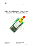
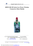
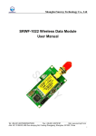
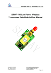
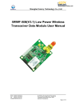
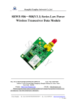
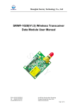
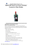
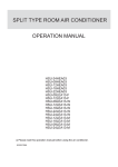
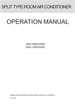
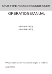
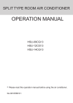
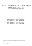
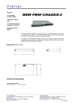
Shanghai Sunray Technology Co., Ltd
SRWF-1021 Series Low Power Wireless
Transceiver Data Module User Manual
_________________________________________________________________________________________________
Tel: +86-021-50275250/50275255
Fax: +86-021-50270187
Add: 201 Keyuan Road. Pudong Zhangjiang, ShangHai, China
http: www.sunrayrf.com
1
Shanghai Sunray Technology Co., Ltd
Contents
I. SRWF-1021 Main Application Range ......................................................... 3
II. Feature of SRWF-1021 Low Power Data RF Module................................ 3
III. Use SRWF-1021 wireless data transceiver module ................................ 5
IV. Setting of the channel, interface, data rate and data format ................. 6
V. Technical specification of SRWF-1021 ................................................... 11
VI. Layout Dimension ................................................................................... 12
VII. Technical Support and After Service .................................................... 12
_________________________________________________________________________________________________
Tel: +86-021-50275250/50275255
Fax: +86-021-50270187
Add: 201 Keyuan Road. Pudong Zhangjiang, ShangHai, China
http: www.sunrayrf.com
2
Shanghai Sunray Technology Co., Ltd
I. SRWF-1021 Main Application Range
SRWF-1021, the low-power wireless transceiver data module is used as the wireless data
transceiver in short-ranges, with the small size, weight and power consumption and good
stability and reliability. Narrowband low power UHF wireless data transmitters and receivers
with channel spacing as low as 50 kHz:
* AMR – Automatic Meter Reading.
* Wireless alarm and security systems.
* Home automation.
* Low power telemetry.
* 433/470 / 868 and 915 MHz ISM/SRD band systems.
* Data radio can be used for Wireless conference voting system.
* Mapping.
* Radio modem can be used for Sports training & competition.
* Wireless dishes ordering.
* Wireless POS, PDA wireless smart terminal.
* RF modem can be used for Electronic bus station and intelligent traffic.
* RF transmitter Wireless electronic display screen and queuing machine.
* Wireless telemetry Charging for parking, parking lot.
* Wireless modem Automobile inspection and four-wheel orientation.
* Wireless sensor Industrial wireless remote control and air conditioning remote controlle.;
* Observation and predication of oil well and hydrological information.;
* Wireless RS232/RS485 conversion/connector.
* Point to multi-point wireless network, wireless on-the-spot bus and automatic data
collection system.
II. Feature of SRWF-1021 Low Power Data RF Module
1. Low power transmission
With the transmission power of 10dBm(433/470MHz), 5dBm( 868/915MHz).
2. ISM frequency band, requiring on application of frequency point.
Carrier frequency of 433MHz(SRWF-1021-433),470MHz(SRWF-1021-470),
868MHz(SRWF-1021-868) , 915MHZ(SRWF-1021-915).
3. High anti- interference and low BER(Bit Error Rate)
_________________________________________________________________________________________________
Tel: +86-021-50275250/50275255
Fax: +86-021-50270187
Add: 201 Keyuan Road. Pudong Zhangjiang, ShangHai, China
http: www.sunrayrf.com
3
Shanghai Sunray Technology Co., Ltd
Based on the GFSK/FSK modulation mode, the high- efficiency forward error correction
channel encoding technology is used to enhance data’s resistance to both burst
interference and random interference and the actual bit error rate of 10-5~10-6 can be
achieved when channel bit error rate is 10-2.
4. Long transmission distance
Within the range of visibility, the reliable transmission distance is >800 m with AT-4
antenna’s height greater than 1m (BER=10-3@433MHz,1200bps).
Within the range of visibility, the reliable transmission distance is >800 m with AT-4
antenna’s height greater than 1m (BER=10-3@470MHz,1200bps).
Within the range of visibility, the reliable transmission distance is >400 m with AT-4
antenna’s height greater than 1m (BER=10-3@868MHz,1200bps).
Within the range of visibility, the reliable transmission distance is >300 m with AT-4
antenna’s height greater than 1m (BER=10-3@915MHz,1200bps).
5. Transparent data transmission
Transparent data interface is offered to suit any standard or nonstandard user protocol.
Any false data generated in the air can be filtrated automatically (What has been received
is exactly what has been transmitted).
6. Multi- channel
The standard SRWF-1021 configuration provides 8 channels. If the user needs, it can be
extended to 16/32 channels, meeting the multiple communication combination mode of
the user.
7. Dual serial port, 3 interface modes
SRWF-1021 provides 2 serial ports and 3 interfaces, with COM1 as the TTL level UART
interface and COM2 as user defined standard RS-232/RS-485 interface (user only needs
to plug/pull 1 bit short circuiter and energize it to make the definition).19200 baud rate only
has TTL level UART interface.
8. Large data buffer zone
Interface baud rate is 1200/2400/4800/9600/19200bps with format of 8N1/8O1/8E1/9N1
and user self-definition, allowing the transmission of long data frames at one time for more
flexible programming by users. (If the user needs, it can also transmit the data in unlimited
length at one time).
9. Intelligent data control and the user doesn’t need to prepare excessive programs
Even for semi duplex communication, the user doesn’t need to prepare excessive
_________________________________________________________________________________________________
Tel: +86-021-50275250/50275255
Fax: +86-021-50270187
Add: 201 Keyuan Road. Pudong Zhangjiang, ShangHai, China
http: www.sunrayrf.com
4
Shanghai Sunray Technology Co., Ltd
programs, only receiving/transmitting the data from the interface. SRWF-1021 will
automatically, complete the other operations, such as transmission/receiving conversion
in the air, control, etc.
10. Low power consumption and sleeping function
+5V supply power, receivering current is 28±2mA, transmitting current is 38±2mA, and
sleep current is 5±2uA.
11. High reliability, small and light
Single chip radio - frequency integrated circuit and single chip MCU are used for lessened
peripheral circuits, high reliability, and low false bit rate.
III. Use SRWF-1021 wireless data transceiver module
1. Appearance chart
SMA
Socket
Antenna
Function
Setting
User interface
2. Interface definition
SRWF-1021 supply 9- pin connector, and its definitions as well as below. Connection
2
1
3
4
5
6
8
7
9
User interface
_________________________________________________________________________________________________
Tel: +86-021-50275250/50275255
Fax: +86-021-50270187
Add: 201 Keyuan Road. Pudong Zhangjiang, ShangHai, China
http: www.sunrayrf.com
5
Shanghai Sunray Technology Co., Ltd
method for terminals is shown in Table 1.
Table 1
Pin No
Description
1
GND
Grounding
Supply
2
VCC
Power supply DC
+3.3~5.0V
3
RXD/TTL
Serial
end
TTL
4
TXD/TTL
Serial data transmitting
end
5
SGND
Grounding of the signal
6
A(TX)
A of RS-485 Or TX
of RS-232
A(RXD)
7
B(RX)
B of RS-485 or RX of
RS-232
B(TXD)
8
SLEEP
Sleep control (Input)
TTL
Sleep signal
Low level enable
t>15ms
9
RESET
Reset control (input)
TTL
Reset signal
Negative pulse
reset 1ms
data
Level
Connected to
Terminal
Item
of
Grounding of
Power
Supply
Power
receiving
Note
TXD
COM1
TTL
RXD
COM2
IV. Setting of the channel, interface, data rate and data format
Before using SRWF-1021, you have to make simple configuration of your system parameter
such as interface and data format. There is one group of 5-bit short-circuiter wire (JP2) on
the bottom right corner of SRWF-1021, defined as A、B 、C、D、E respectively.
_________________________________________________________________________________________________
Tel: +86-021-50275250/50275255
Fax: +86-021-50270187
Add: 201 Keyuan Road. Pudong Zhangjiang, ShangHai, China
http: www.sunrayrf.com
6
Shanghai Sunray Technology Co., Ltd
1.channel configuration
ABC jumper wires of JP2 provide 8 options and you can choose to use 0-7 channels .if the
work wireless module is work at the same channel (ABC jumper wire mode is same), you
can transmit data between each module but keep in mind, at the same time only one
module is in TX mode. More detail is Table 3.
Table3
JUMPER
ABC
CHANNEL
NUMBER
PROGRAM
–FREQENC
Y(433MHz)
PROGRAM
–FREQENC
Y(470MHz)
PROGRAM
–FREQENC
Y(868MHz)
PROGRAM
–FREQENC
Y(915MHz)
0(ABC NO
SHORT)
433.85
470.25
869.43
915.0
1
432.10
470.36
869.49
915.2
2
433.20
470.49
869.56
915.4
3
433.25
470.10
869.62
915.6
4
434.00
470.652
867.8
915.8
_________________________________________________________________________________________________
Tel: +86-021-50275250/50275255
Fax: +86-021-50270187
Add: 201 Keyuan Road. Pudong Zhangjiang, ShangHai, China
http: www.sunrayrf.com
7
Shanghai Sunray Technology Co., Ltd
5
432.65
470.842
868.0
916.0
6
433.40
470.90
868.2
916.2
7
432.60
470.72
868.4
916.4
2. Selection of interface mode
SRWF-1021 provides 2 serial ports. COM1 (Pin3 and Pin4 of JP1) is fixed as UART serial
port of TTL level; COM2 (Pin6 and Pin7 of JP1) can choose interface mode through D of
JP2:
1) TTL interface connection application circuit.
NOTE: Please do not connect any wire on PIN7and PIN8 if com2 is no use
If you use the TTL only please make sure the D jumper of JP2 without jumper wire.
2) RS-232 interface connection application circuit.
D=1( with short jumper as:
)
_________________________________________________________________________________________________
Tel: +86-021-50275250/50275255
Fax: +86-021-50270187
Add: 201 Keyuan Road. Pudong Zhangjiang, ShangHai, China
http: www.sunrayrf.com
8
Shanghai Sunray Technology Co., Ltd
3) RS-485 Interface connection application circuit.
D=0( without short jumper as: )
NOTE: Please do not connect any wire on PIN3and PIN4 if com1 is no use, if the two use
different Power supply please make sure the two use the same GND (join the two’s
GND together).
3. Interface rate setting
The rate of SRWF-1021 is determined by hardware; to make sure the module rate is suit
to your system, we are must be told your system’s rate.
4.SRWF-1021 can support no parity and even parity mode it can chose parity mode
through E of JP2
E=0 (without short circuiter) parity
8E1/8O1/9N1
E=1 (with short circuiter) parity
8N1
NOTE: Channel setting, Com2’s Interface mode and parity mode is fixed after the power is
on if you want to change the setting, you must reset the module or Power on again.
5.Time delay Diagram
1) The Pin8 ‘SLP’ in JP1 is the signal of sleep control. In low power level, when the
_________________________________________________________________________________________________
Tel: +86-021-50275250/50275255
Fax: +86-021-50270187
Add: 201 Keyuan Road. Pudong Zhangjiang, ShangHai, China
http: www.sunrayrf.com
9
Shanghai Sunray Technology Co., Ltd
transceiver stays in sleep mode, the conversion from idle mode to sleep will be finished
in 6ms. If the Sleep signal arrives when the transceiver is transmitting data, the module
will enter sleep mode after finishing transmission. From sleep mode to transceiver mode,
it takes when the RST signal comes.
2) The delay time (Tc) of conversion between transmitting and receiving is less than 3ms.
The delay time of transceivers between the first bit sent by TXD to the first bit
received by RXD. Due to a data processing will be made on user’s data by SRWF-1021
transceiver using FEC(Forward Error Correction) or other correction algorithm, when RXD
of a SRWF-1021 transceiver ‘A’ receives the data, then transmits it, the other one
transceiver ‘B’ will have a delay (Td) to receive and transmit by TXD. Different RF data
rate causes different delay time. Please see the specific delay time below:
Baudrate(bps)
Delay Time(Td/ms)
1200
122
2400
58
4800
31
9600
16
19200
8
_________________________________________________________________________________________________
Tel: +86-021-50275250/50275255
Fax: +86-021-50270187
Add: 201 Keyuan Road. Pudong Zhangjiang, ShangHai, China
http: www.sunrayrf.com
10
Shanghai Sunray Technology Co., Ltd
6.Indicator Function
When transmitting mode, the red indicator light will twinkle .(only UART TTL)
When in receiving mode, the green indicator light will twinkle.(only UART TTL )
V. Technical specification of SRWF-1021
Serial
number
Item
1
Modulation mode
GFSK/FSK
2
Work frequency
433/470/868/915MHz
3
Transmission
power
10dBm(433/470MHz),5dBm(868/915MHz)
4
Receiving
sensitivity
Parameter
-118 dBm
433MHz@1200bps
-118 dBm
470MHz@1200bps
-116 dBm
868MHz@1200bps
-116 dBm
915MHz@1200bps
16/32 channel
custom-made
5
Channel counts
8channel
6
Transmitting
current
38±2mA
7
Receiving current
28±2mA
8
Sleeping current
5±2uA
9
Interface velocity
1200/2400/4800/9600/19200bps
10
Interface mode
UART TTL/RS-232/RS-485
11
Power supply
+3.3~5VDC
12
Working
temperature
-25℃~75℃
13
Working humidity
10%~90%(relative humidity without
condensation)
14
Dimension
47mm×26mm×10mm
15
Reliable transmit
distance
Note
-40℃~60℃
User setting,
19200 bps TTL
only
-40℃~85℃
custom-made
800m@ AT-4 antenna
433MHz@1200bps
800m@ AT-4 antenna
470MHz@1200bps
400m@ AT-4 antenna
868MHz@1200bps
300m@ AT-4 antenna
915MHz@1200bps
_________________________________________________________________________________________________
Tel: +86-021-50275250/50275255
Fax: +86-021-50270187
Add: 201 Keyuan Road. Pudong Zhangjiang, ShangHai, China
http: www.sunrayrf.com
11
Shanghai Sunray Technology Co., Ltd
VI. Layout Dimension
VII. Technical Support and After Service
We provide full technical support for our clients on applications and secondary development.
Our products have one-year warranty and perpetual maintenance services.
_________________________________________________________________________________________________
Tel: +86-021-50275250/50275255
Fax: +86-021-50270187
Add: 201 Keyuan Road. Pudong Zhangjiang, ShangHai, China
http: www.sunrayrf.com
12