1
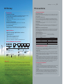
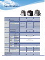
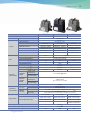
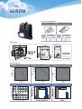
Technical Data
EV Relay
02_EV Relay Technical Data
Safety is first priority with LSIS`s proven technology!
Starting with G7 EV (Electric Vehicle) Korean National project in 1993, LSIS has developed key
EV components such as Power Control Unit (PCU), EV-relay and On Board Charger (OBC) equipped in
pure electric vehicle (EV), hybrid electric vehicle (HEV), plug-in hybrid electric vehicle (PHEV) and
fuel cell electric vehicle (FCEV). Our capability of manufacturing Power Control Unit (PCU) is derived
from the 20 years of experience in electric power and automation/drive business. Also, our capability
for developing and producing high voltage EV-Relay is through business experience over 30 years
and domestic market share of 65% in magnetic contactor & circuit breaker. Because of our unique
experience, safety and durability is our strength, and our ultimate target is to achieve zero accident
caused by our product failure.
_03
EV Relay Technical Data
EV Relay
Precautions
Safety Precautions
Features
Specification range
Compact Design
Achieved overall compact size with short gap cutoff,
charged with Hydrogen and Nitrogen Gas.
Use that exceeds the specification ranges such as the coil rating, contact rating
and switching life should be avoided. Doing so may lead to abnormal heating,
smoke, and fire.
Installation, maintenance
Proven Safety
Never touch live parts when power is applied to a relay. Doing so may cause
electrical shock. When installing, maintaining, or trouble shooting, the power
of relays and connecting parts such as terminals and sockets must be turned off.
High Short-time short circuit current with
stand value.
Connection
Superior Reliability
Be warned that an incorrect connection may lead to unexpected operation
error, abnormal heating, and fire.
Excellent performance with electrical and
mechanical endurances.
Fail-safe
Customizable
Relays are customizable to meet customers`
requirements such as mounting position, etc.
If the possibility exists that faulty adhesion or contact could endanger assets or
human life, take double safety precautions and make sure that operation is
foolproof.
Right Connection of HV Terminal
GER-Relays’ contacts have polarity. Make sure to perform connections with the
correct polarity as indicated on the frame. If the contacts are connected with
the reverse polarity, the switching characteristics specified in this document
cannot be assured.
Applications
High DC voltage applications such as
Tightening Torque
Below torque guide must be followed.
M4 screw : 1.8 to 2.7 N.m
M5 screw : 3 to 4 N.m
Electric Vehicle
Hybrid Vehicle
Renewable Energy Storage
Battery Charging System
Fuel Cell & Solar System
General-purpose Industrial Equipments
M6 screw : 6 to 8 N.m
M8 screw : 10 to 12 N.m
Wire Size for HV connection
Model
GER010
GER040
GER100
GER150
GER250
GER400
Model Number Structure
GER
Recommendation
2mm2
10mm2
35mm2
70mm2
150mm2
240mm2
Usage Ambient Condition
To maintain initial performance, do not drop or apply physical impact to the relay.
Component
G : Global
E : Electric Vehicle
R : Relay
Contact Rating
010 : 10A
040 : 40A
100 : 100A
150 : 150A
250 : 250A
400 : 400A
Coil Voltage
12 : 12Vdc
24 : 24Vdc
Customer
LS
Model
ST
Mount Type
SM : Side Mount
BM : Bottom Mount
PI : Plug-In type
Warranty
LSIS warrants that the products shall be free from defects in material and workmanship for
a period of twelve (12) months from the manufacturing date of the products. If any defect due
to LSIS’ failure, the extent of LSIS’ liability under this warranty shall be limited to, at LSIS’
option, the repair, replacement. LSIS’ obligation regarding to this warranty is conditioned
upon the submission to LSIS of a written service request which specifies the defect and the
relevant evidence within seven (7) days from the date recognizing the defect.
Notwithstanding the foregoing, the warranty above shall not apply, if the products have been
subjected to misuse, abuse, negligence, improper installation, improper maintenance,
improper transportation, accident, alteration or design change by anyone other than LSIS, or
if the original name, serial number and/or identification marking have been defaced, altered
or removed, or the products haven used in violation of instructions furnished by LSIS.
Under any circumstance, LSIS shall not have any other obligations, guaranties, conditions or
liabilities, express or implied arising by law or otherwise (including, without limitation, any
obligation of LSIS with respect to consequential damages) and whether or not occasioned by
LSIS’ negligence, than the above statement and shall not be extended, altered or varied.
Under normal use, the relay is designed not to be detached. To maintain initial
performance, the case should not be disassembled. Relay characteristics
cannot be guaranteed if the case is removed.
Magnetism
If relays are proximately installed next to each other or installed near highlymagnetized parts such as motor or speaker, the operational characteristics
might get changed or malfunction can happen. Hence, please verify this point
in actual installation and operational condition.
Shock
It is ideal to mount the relay that the movement of the contacts and movable
parts is perpendicular to the direction of the vibration or shock. Especially, note
that the vibration and shock resistance of NC contacts while the coil is not
excited is greatly affected by the mounting direction of the relay. Condensation
could be formed when there is a sudden change in temperature under high
temperature, high humidity conditions. Note that condensation may cause
deterioration of the insulation, breaking of coil, and rusting.
Storage, Transpoation
Transportation
Relay’s functional damage may occur if strong vibration, shock or heavy weight
is applied to a relay during transportation of a device in which a relay is
installed. Therefore, please pack them in a way, using shock-absorbing
material, so that the allowable range for vibration and shock is not exceeded.
Storage
If the relay is stored for extended periods of time (including transportation
period) at high temperatures or high humidity levels or in atmospheres with
organic gas or sulfide gas, sulfide film or oxide film may be formed on surface
of the contacts, which may cause contact instability, contact failure and
functional failure. Please check the atmosphere in which the units are to be
stored and transported.
04
EV Relay Technical Data
Specifications
Model
Width x Height x Depth(mm)
Item
Characteristics
Contact Form
Contact Structure
Contact Resistance
Contact
Short-time Current
Max. Cut-off Current
Reverse direction Cut-off
Overload Interruption
Coil
Electrical
Characteristics
Mechanical
Characteristics
Rated Voltage
Pick-up Voltage(@20 )
Drop-out Voltage(@20 )
Coil resistance(@20 )
Power Consumption
Max. Allowable Voltage
Operating Time(@20 )
Release Time(@20 )
Bounce Time(@20 )
Between Coil
Insulation
and Contacts
Resistance
Between Contacts of
(Initial)
the Same Polarity
Between Coil
Dielectric
and Contacts
Strength
Between Contacts of
(Initial)
the Same Polarity
Impulse Withstand Voltage
Shock
Functional
Resistance
Destructive
Functional
Vibration
Resistance
Destructive
Mechanical
Expected Life
Electrical(Resistive Load)
Ambient Operating Temp.
Ambient Operating Humidity
Weight
GER010
GER040
GER100
34 x 44 .3x 28
67 x 47 x 35.3
Specifications
SPST-NO
Double Break, Single
Max.10mΩ
65A(15min.)
100A(2min.)
400A @450V(1Cycle)
-40A 200V(5,000cycles)
80.7 x 70 x 39
Max. 2mΩ
150A(15min., 35mm2)
225A(2min., 35mm2)
1,000A 450Vdc(1cycle)
-100A 200V(2,000cycles)
120A 450VDC(100Cycles)
200A 450VDC(100cycles)
Max. 50mΩ
15A(2min., 2mm2)
30A(30sec., 2mm2)
15A 400VDC(10,000Cycles)
30A 400VDC(50Cycles)
60.8
2.5W
Max. 1ms
12V
75% Max. of Rated Voltage
10% Min. of Rated Voltage
49.3
3W
16VDC
Max. 30ms
Max. 10ms
Max. 1.5ms
33
4.5W
Max. 3ms
Min. 1,000MΩ(@500VDC)
2,500Vrms /min.
(Detection Current :10mA)
4,500V
Min.196m/s2 (20G)
Min.490m/s2 (50G)
10 to 200 increments of 10, Min. 4.5G(Detection Time : 10 )
10 to 200Hz, Min.4.5G
(Time of vibration for each direction ; X, Y, Z Direction : 4hours)
Min. 250,000ops.
Min. 200,000ops.
Min. 200,000ops.
-
450Vdc 40A, 5,000ops.
450Vdc 100A 2,000ops.
400Vdc15A, 75,000ops.
(only Making)
450Vdc 30A, 10,000ops.
450Vdc 30A, 80,000ops.
(only Making)
-40 ~ 85
5 ~ 95%R.H.
140g
450Vdc 40A 30,000ops.
450Vdc 120A, 80,000ops.
(only Making)
77g
Note 1. Number of operations for overload interruption and expected life can change due to environmental conditions.
2. L/R 1ms for circuit setup.
350g
EV Relay Technical Data
Model
GER150
GER250
GER400
80.7 x 70 x 39
111 x 63 x 74.7
Max. Cut-off Current
Reverse direction Cut-off
Max. 2mΩ
225A(10min., 50mm2)
320A(2min., 50mm2)
1,500A 450Vdc(1cycle)
-150A 200V(1,500cycles)
91.5 x 89 x 45
Specifications
SPST-NO
Double Break, Single
Max. 1mΩ
350A(10min., 100mm2)
500A(2min., 100mm2)
2,500A 450Vdc(1cycle)
-250A 200V(5,000cycles)
Max. 1mΩ
600A(10min., 150mm2)
900A(2min., 150mm2)
3,200A 450Vdc(1cycle)
-100A 200V(2,000cycles)
Overload Interruption
300A 450VDC(100cycles)
400A 450VDC(100cycles)
800A 450VDC(300cycles)
Width x Height x Depth(mm)
Item
Characteristics
Contact Form
Contact Structure
Contact Resistance
Contact
Coil
Electrical
Characteristics
Mechanical
Characteristics
Short-time Current
Rated Voltage
Pick-up Voltage(@20 )
Drop-out Voltage(@20 )
Coil resistance(@20 )
Power Consumption
Max. Allowable Voltage
Operating Time(@20 )
Release Time(@20 )
Bounce Time(@20 )
Between Coil
Insulation
and Contacts
Resistance
Between Contacts of
(Initial)
the Same Polarity
Between Coil
Dielectric
and Contacts
Strength
Between Contacts of
(Initial)
the Same Polarity
Impulse Withstand Voltage
Shock
Functional
Resistance
Destructive
Functional
Vibration
Resistance
Destructive
Mechanical
Expected Life
05
Electrical(Resistive Load)
Ambient Operating Temp.
Ambient Operating Humidity
Weight
12V
23.5
6W
Max. 2ms
12V(24V)
75% Max. of Rated Voltage
10% Min. of Rated Voltage
38.2
38.9
4W(*Inrush current : 2.5A for 12V) 4W(*Inrush current : 3A for 12V)
16VDC
Max. 30ms
Max. 10ms
Max. 3ms
Max. 3ms
Min. 1,000MΩ(@500Vdc)
2,500Vrms/min
(Detection Current : 10mA)
4,500V
Min.196m/s2(20G)
Min.490m/s2(50G)
10 to 200 increments of 10, Min. 4.5G(Detection Time : 10 )
10 to 200Hz, Min.4.5G
(Time of vibration for each direction ; X, Y, Z Direction : 4hours)
Min. 300,000ops.
Min. 300,000ops.
Min. 300,000ops.
450Vdc 400A 2,000ops.
450Vdc 150A 1,500ops.
450Vdc 250A 3,000ops.
450Vdc 200A 10,000ops.
400VDC 15A 80,000ops. 400VDC 100A 10,000ops. 450VDC 200A 10,000ops
-
-
450VDC 40A 80,000ops
380g
-40 ~ 85
5 ~ 95%R.H.
500g
700g
Note 1. Number of operations for overload interruption and expected life can change due to environmental conditions.
2. L/R 1ms for circuit setup.
06_EV Relay Technical Data
GER010
Terminal
LV terminal
HV terminal
Pin Type Features:
Terminal Type = Tab
Mating Area Interface
Dimensions (mm) 6.3x 0.80
Material = Brass
Applicable Connector:
Terminal Type = Receptacle3
Tyco 63445-2
Pin Type Features:
Terminal Type = Tab
Mating Area Interface
Dimensions (mm) 4.8 X 0.80
Material = Brass
Applicable Connector:
Terminal Type = Receptacle
Tyco 9-160481-x Series
Tyco 1-160477-x Series
Dimensions
General Tolerance
less than 10: ±0.25
10~50: ±0.5
more than 50: ±0.8
Engineering Data
Cut-off life curve
Operating Voltage characteristics
Note : I-T curve at ambient temperature of 23℃
Current distribution
Low Voltage distribution
Time distribution
_07
EV Relay Technical Data
GER040
Connector Information
Housing : 1379658
Connector Style =
Receptacle
Contact Type = Tab
Receptacle
Configuration = 025
Terminal : 1123343
Contact Type = Receptacle
Applies To Wire/Cable
Wire/Cable Type =
Discrete Wire
Wire Range = 0.20-0.602
[24-20] mm [AWG]
Dimensions
General Tolerance
less than 10: ±0.25
10~50: ±0.5
more than 50: ±0.8
Engineering Data
Cut-off life curve
Switching life curve
Current distribution
Operating Voltage characteristics
Low Voltage distribution
Time distribution
Note : I-T curve at ambient temperature of 23℃
08_EV Relay Technical Data
GER100
Connector Information
Housing:MG651026(L)
Terminal:ST730676-3
Material
Wire Range
Part No.
ST30676-3
AWG
mm2
18-16
AVSS(CAVS)
0.85~1.25
Tab Thick
0.64
Thick
Finish
0.25
Copper Alloy
Pre-Tin
Dimensions
General Tolerance
less than 10: ±0.25
10~50: ±0.5
more than 50: ±0.8
Engineering Data
Cut-off life curve
Switching life curve
Current distribution
Operating Voltage characteristics
Low Voltage distribution
Time distribution
Note : I-T curve at ambient temperature of 23℃
_09
EV Relay Technical Data
GER150
Connector Information
Housing:MG651026(L)
Terminal:ST730676-3
Material
Wire Range
Part No.
ST30676-3
AWG
mm2
18-16
AVSS(CAVS)
0.85~1.25
Tab Thick
0.64
Thick
Finish
0.25
Copper Alloy
Pre-Tin
Dimensions
General Tolerance
less than 10: ±0.25
10~50: ±0.5
more than 50: ±0.8
Engineering Data
Cut-off life curve
Switching life curve
Current distribution
Operating Voltage characteristics
Low Voltage distribution
Time distribution
Note : I-T curve at ambient temperature of 23℃
10_EV Relay Technical Data
GER250
Connector Information
Housing:MG651026(L)
Terminal:ST730676-3
Material
Wire Range
Part No.
ST30676-3
AWG
mm2
18-16
AVSS(CAVS)
0.85~1.25
Tab Thick
0.64
Thick
Finish
0.25
Copper Alloy
Pre-Tin
Dimensions
General Tolerance
less than 10: ±0.25
10~50: ±0.5
more than 50: ±0.8
Engineering Data
Cut-off life curve
Switching life curve
Current distribution
Operating Voltage characteristics
Low Voltage distribution
Time distribution
Note : I-T curve at ambient temperature of 23℃
_11
EV Relay Technical Data
GER400
Connector Information
Housing:MG651026(L)
Terminal:ST730676-3
Material
Wire Range
Part No.
ST30676-3
AWG
mm2
18-16
AVSS(CAVS)
0.85~1.25
Tab Thick
0.64
Thick
Finish
0.25
Copper Alloy
Pre-Tin
Dimensions
General Tolerance
less than 10: ±0.25
10~50: ±0.5
more than 50: ±0.8
Engineering Data
Cut-off life curve
Switching life curve
Current distribution
Operating Voltage characteristics
Low Voltage distribution
Time distribution
Note : I-T curve at ambient temperature of 23℃
� For your safety, please read user's manual thoroughly before operating.
� Contact the nearest authorized service facility for examination, repair, or adjustment.
� Please contact qualified service technician when you need maintenance.
Do not disassemble or repair by yourself !
Safety Instructions
� Any maintenance and inspection shall be performed by the personnel having expertise concerned.
ⓒ 2011.06 LSIS Co., Ltd. All Rights Reserved.
�LSIS Shanghai Office �
�Shanghai, China
HEAD OFFICE
LS-ro 127(Hogye-dong), Dongan-gu, Anyang-si,
Gyeonggi-do 431-848, Korea
Tel : +82-2-2034-4058~9, 4093
E-mail : [email protected]
Fax : +82-2-2034-4622
Address Room E-G. 12FL Huamin Empire Plaza. No.726. West Yan'an Road Shanghai 200050. P.R. China
Tel +86-21-5237-9977(501) Fax +89-21-5237-7189 E-mail [email protected]
�LSIS Beijing Office �
�Beijing, China
Address B-Tower 17FL. Beijing Global Trade Center. No. 36. East BeisanHuan-Road. DongCheng-District.
Beijing 100013. P.R. China
Tel +86-10-5825-6027(666) Fax +86-10-5825-6028 E-mail [email protected]
�LSIS Guangzhou Office �
�Guangzhou, China
Address Room 1403.14FL. New Poly Tower. 2 Zhongshan Liu Road.Guangzhou.P.R China
Tel +86-20-8326-6754 Fax +86-20-8326-6287 E-mail [email protected]
�LSIS Chengdu Office �
�Chengdu, China
� Global Network
�LSIS Detroit Office >> Detroit, USA
Adderss 5700 Crooks Rd Suite 211 Troy, MI 48098, Detroit, USA
Tel +1-248-792-2638 Fax +1-248-792-2642 E-mail [email protected]
�LSIS Europe B.V. >> Amsterdam, Netherlands
Address Room 1710.17FL. Huamin Empire Plaza. No.1 Fu Xing Street.Chengdu.610016. P.R. China
Tel +86-28-8670-3201 Fax +86-28-8670-3203 E-mail [email protected]
�LSIS Qingdao Office �
�Qingdao, China
Address Room 2001.YinHe Bldg. No. 29 Shandong Road, Qingdao. 266071, P.R. China
Tel +86-532-8501-6058 Fax +86-532-8501-6057 E-mail [email protected]
Address 1st. Floor, Tupolevlaan 48, 1119NZ, Schiphol-Rijk, The Netherlands
Tel +31-20-654-1420 Fax +31-20-654-1429 E-mail [email protected]
�LSIS(ME) FZE �
�Dubai, U.A.E.
Address Jafza View Tower Lob 19, Room 205 Along Sheikh Zayed Road Jebel Aali Free Zone Dubai,
United Arab Emirates,
Tel + 971-4-886-5360 Fax + 971-4-886-5361 E-mail [email protected]
�LSIS(Dalian) Co., Ltd �
�Dalian, China
Address No. 15.Liaohexi 3-Road. Economic and Technical Development zone. Dalian 116600. China
Tel +86-411-8730-7510 Fax +86-411-8731-8277 E-mail [email protected]
�LSIS(Wuxi) Co., Ltd �
�Wuxi, China
Address 102-A. National High & New Tech Industrial Development Area. Wuxi.
Jiangsu. 214028. P.R. China
Tel +86-510-8534-6666 Fax +86-510-8534-4078 E-mail [email protected]
�LS-VINA IS Co., Ltd �
�Hanoi, Vietnam
Address Nguyen Khe Dong Anh, Hanoi
Tel +84-4-38820 222,3 Fax +84-4-38820 220 E-mail [email protected], [email protected]
�LSIS Tokyo Office �
�Tokyo, Japan
Address 16FL. Higashi-Kan. Akasaka Twin Tower 2-17-22. Akasaka. Minato-ku Tokyo 107-0052. Japan
Tel +81-3-3582-9128 Fax +81-3-3582-2667 E-mail [email protected]
2012. 12
Specifications in this catalog are subject to change without notice due to
continuous product development and improvement.
EV Relay Technical Data(E) 2011. 06/(05) 2012. 12 Printed in Korea HumanPower