1
K R A ME R E LE CT R O N IC S L TD .
USER MANUAL
MODEL:
SID-X3N
Step-in Commander
P/N: 2900-300304 Rev 3
Contents
1
Introduction
1
2
2.1
2.2
2.3
2.4
Getting Started
Achieving the Best Performance
Safety Instructions
Shielded Twisted Pair/Unshielded Twisted Pair
Recycling Kramer Products
2
2
2
3
3
3
Overview
4
4
Defining the SID-X3N Step-in Commander
6
5
5.1
5.2
5.3
6
6.1
6.2
6.3
7
7.1
7.2
7.3
7.4
7.5
Connecting the SID-X3N
Connecting the Remote Step-In Switch and LED
Connecting the Remote Select Switch and LED
Connecting the Remote Input Selection LEDs
Principles of Operation
Video Input Selection
Audio Signal Control
Automatic Output Shutdown
Operating the SID-X3N
Manually Selecting an Input
Taking Control of the Switcher Input When Connected to the VS-62H
Locking the EDID
Audio Mode Selection
Adjusting the UXGA Input Phase
8
9
10
11
12
12
13
13
14
14
15
15
15
15
8
8.1
9
9.1
Configuring the SID-X3N
Setting the Configuration DIP-switch
Technical Specifications
Supported Resolutions
16
16
18
19
10
10.1
10.2
11
11.1
11.2
Default EDID
HDMI, DisplayPort and DVI
PC-UXGA
Protocol 2000
Syntax
Instruction Codes
21
21
23
25
25
26
12
12.1
12.2
Protocol 3000
Kramer Protocol 3000 Syntax
Kramer Protocol 3000 Commands
28
28
31
Figures
Figure 1: SID-X3N Step-in Commander Front Panel
Figure 2: SID-X3N Step-in Commander Rear Panel
Figure 3: Connecting the SID-X3N Step-in Commander
Figure 4: Remote Step-In Switch and LED Wiring
Figure 5: Remote Select Switch and LED Wiring
Figure 6: Remote Input Indicator LED Connections
Figure 7: Remote Input Indicator LED Wiring
Figure 8: The Configuration DIP-switch
6
7
8
9
10
11
11
16
SID-X3N – Contents
i
1
Introduction
Welcome to Kramer Electronics! Since 1981, Kramer Electronics has been
providing a world of unique, creative, and affordable solutions to the vast range of
problems that confront video, audio, presentation, and broadcasting professionals
on a daily basis. In recent years, we have redesigned and upgraded most of our
line, making the best even better!
Our 1,000-plus different models now appear in 14 groups that are clearly defined
by function: GROUP 1: Distribution Amplifiers; GROUP 2: Switchers and Routers;
GROUP 3: Control Systems; GROUP 4: Format/Standards Converters; GROUP 5:
Range Extenders and Repeaters; GROUP 6: Specialty AV Products; GROUP 7:
Scan Converters and Scalers; GROUP 8: Cables and Connectors; GROUP 9:
Room Connectivity; GROUP 10: Accessories and Rack Adapters and GROUP 11:
Sierra Video Products; GROUP 12: Digital Signage; and GROUP 13: Audio, and
GROUP 14: Collaboration.
Thank you for purchasing the Kramer MegaTOOLS® SID-X3N Step-in
Commander which is ideal for:
Display systems requiring simple input selection
Remote monitoring of computer activity in schools and businesses
Rental/staging applications
Multimedia and presentation source selection
SID-X3N - Introduction
1
2
Getting Started
We recommend that you:
Unpack the equipment carefully and save the original box and packaging
materials for possible future shipment
Review the contents of this user manual
i
2.1
Go to http://www.kramerelectronics.com/support/product_downloads.asp
to check for up-to-date user manuals, application programs, and to check if
firmware upgrades are available (where appropriate).
Achieving the Best Performance
To achieve the best performance:
Use only good quality connection cables (we recommend Kramer highresolution, high-quality cables) to avoid interference, deterioration in signal
quality due to poor matching, and elevated noise levels (often associated
with low quality cables)
Do not secure the cables in tight bundles or roll the slack into tight coils
Avoid interference from neighboring electrical appliances that may adversely
influence signal quality
Position your Kramer SID-X3N away from moisture, excessive sunlight and
dust
!
2.2
Safety Instructions
!
2
This equipment is to be used only inside a building. It may only be
connected to other equipment that is installed inside a building.
Caution:
There are no operator serviceable parts inside the unit
Warning:
Use only the Kramer Electronics input power wall
adapter that is provided with the unit
Warning:
Disconnect the power and unplug the unit from the wall
before installing
SID-X3N - Getting Started
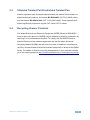
2.3
Shielded Twisted Pair/Unshielded Twisted Pair
Kramer engineers have developed special twisted pair cables to best match our
digital twisted pair products; the Kramer BC-DGKat623 (CAT 6 23 AWG cable),
and the Kramer BC-DGKat7a23 (CAT 7a 23 AWG cable). These specially built
cables significantly outperform regular CAT 6 and CAT 7a cables.
2.4
Recycling Kramer Products
The Waste Electrical and Electronic Equipment (WEEE) Directive 2002/96/EC
aims to reduce the amount of WEEE sent for disposal to landfill or incineration by
requiring it to be collected and recycled. To comply with the WEEE Directive,
Kramer Electronics has made arrangements with the European Advanced
Recycling Network (EARN) and will cover any costs of treatment, recycling and
recovery of waste Kramer Electronics branded equipment on arrival at the EARN
facility. For details of Kramer’s recycling arrangements in your particular country
go to our recycling pages at http://www.kramerelectronics.com/support/recycling/.
SID-X3N - Getting Started
3
3
Overview
The SID-X3N accepts an HDMI, DisplayPort, DVI and PC graphics video input, as
well as an unbalanced stereo audio input (which is embedded into the output
signal), and transmits the signal via HDMI cable to a compatible switcher, (for
example, the VS-62H). The device also provides an unbalanced, stereo audio
output. When the SID-X3N is connected to a switcher, it can also control the input
selection of the switcher.
In particular the SID-X3N features:
HDTV support
HDMI with Deep Color, x.v.Color™ and 3D
HDCP compliancy—works with sources that support HDCP repeater mode
Note: When using a MacBook as a source and the content is protected
using HDCP, if the display does not support HDCP, no video is transmitted
Input signal detection based on video clock presence
Automatic input selection based on manual selection or last connected input
Automatic analog audio detection and embedding
Automatic output shutdown when the input signal is lost (with a configurable
delay)
Programmable step-in functionality (when used with the VS-62H connected
via an HDMI cable that supports HEC, HDMI Ethernet Channel)
I-EDIDPro™ Kramer Intelligent EDID Processing™ – Intelligent EDID
handling & processing algorithm ensures Plug and Play operation for HDMI
systems
A lockable EDID
VGA phase adjustment
Power-over-Ethernet passes electrical power along with data on Ethernet
cabling. This allows a single cable to provide both data connection and
electrical power to compatible devices
4
SID-X3N - Overview
Equalization and reclocking of the data
A maximum data rate of 6.75Gbps (2.25Gb per graphics channel)
Support for digital audio formats
A MegaTOOLS® sized enclosure. Two devices can be mounted in a rack
using the optional RK-T2B adapter
You can control the SID-X3N using the front panel buttons, or remotely via contact
closure switches.
SID-X3N - Overview
5
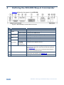
4
Defining the SID-X3N Step-in Commander
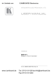
Figure 1 defines the front panel of the SID-X3N.
Figure 1: SID-X3N Step-in Commander Front Panel
#
Feature
Function
1
AUDIO IN 3.5mm Mini Jack
Connect to an unbalanced stereo audio source
2
3
4
LED
Lights green when the HDMI input is selected
HDMI Connector Connect to an HDMI source
LED
Lights green when the DisplayPort input is selected
DP Connector
Connect to a DisplayPort source
LED
Lights green when the DVI input is selected
DVI Connector
Connect to a DVI source
8
LED
Lights green when the PC-UXGA input is selected
9
PC-UXGA
PC-UXGA
15-pin HD
Connector (F)
Connect to a PC graphics source
10
INPUT SELECT Button
Press repeatedly to cycle through the inputs manually to
select an input signal and override the automatic selection,
(see Section 7.1)
Note: When the button is lit it is inactive and pressing the
button will not activate the input
11
STEP-IN Button
Press to activate the input on the switcher that the
SID-X3N is connected to, (see Section 7.2)
12
ON LED
Lights green when the device is powered on
5
6
7
6
HDMI
DisplayPort
DVI
SID-X3N - Defining the SID-X3N Step-in Commander
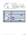
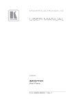
Figure 2 defines the rear panel of the SID-X3N.
Figure 2: SID-X3N Step-in Commander Rear Panel
#
Feature
Function
1
AUDIO OUT 3.5mm Mini Jack
Connect to an unbalanced, stereo audio acceptor, (see
Section 4)
2
HDMI OUT Connector
Connect to a compatible switcher, for example, VS-62H using an
HDMI cable
3
REMOTE STEP-IN LED
3-pin Terminal
Switch
Block
Connect to the anode of the remote Step-In LED indicator
PROG RS-232 3-pin Terminal
Block
Connect to the PC via RS-232 to perform a firmware upgrade
4
5
6
LED
Connect to the remote, Step-In switch, (see Section 5.1)
Connect to the anode of the remote Input Select LED indicator,
(see Section 4)
8
REMOTE
Switch
SELECT 8-pin
Terminal Block LED HDMI,
DP, DVI and
UXGA
9
OPTION 8x DIP-switch
Used to set the device behavior, (see Section 8)
10
USB POWER Connector
Provides 5V DC power to a device, (max 1.5A)
11
12V DC Power Connector
Connect to supplied power adapter, center pin positive
7
Connect to the remote, Input Select switch, (see Section 5.2)
Connect to the anodes of the remote input indicators
(see Section 5.3)
SID-X3N - Defining the SID-X3N Step-in Commander
7
5
Connecting the SID-X3N
i
Switch off the power to all devices before connecting them to your
SID-X3N. After connecting your SID-X3N connect the power to other
devices.
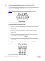
Figure 3: Connecting the SID-X3N Step-in Commander
To connect the SID-X3N as illustrated in Figure 3:
1. Connect up to four video sources, (for example, a Blu-ray disc player, a
laptop, and two computer graphics sources) to the video input connectors.
2. Connect the unbalanced stereo audio source, (for example, the audio output
of the laptop) to the AUDIO IN 3.5mm mini jack.
8
SID-X3N - Connecting the SID-X3N
3. Connect the AUDIO OUT 3.5mm mini jack to the unbalanced, stereo audio
acceptor, (for example, a power amplifier with speakers).
4. Connect the HDMI OUT connector to a compatible switcher, (for example,
VS-62H or KW-11T).
5. Connect the REMOTE STEP-IN 3-way terminal block to a contact closure
switch and LED, (see Section 5.1).
6. Connect the REMOTE SELECT 3-way terminal block to a momentary
contact closure switch and LEDs, (see Section 5.2).
7. Connect the LED ANODES 5-way terminal block to the remote input
indicator LEDs, (see Section 5.3).
8. If required, connect a device requiring a 5V DC power supply, (for example,
the KW-11T, not shown in Figure 3).
9. Connect the power adapter to the SID-X3N and to the mains power, (not
shown in Figure 3).
Note: All LED supplies include a current limiting resistor and are designed to work
with any standard LED.
5.1
Connecting the Remote Step-In Switch and LED
You can connect a remote, contact closure step-in switch to take control of the
input of the attached switcher, as well as a remote step-in LED to the REMOTE
STEP-IN terminal block on the rear panel of the SID-X3N.
Figure 4 illustrates the connections from the terminal block to the switch and LED.
Figure 4: Remote Step-In Switch and LED Wiring
SID-X3N - Connecting the SID-X3N
9
To connect a remote step-in switch and LED as illustrated in the example in
Figure 4:
1. Connect pins 2 and 3 from the terminal block to the remote step-in switch.
2. Connect pin 1 from the terminal block to the anode of the remote step-in
LED.
3. Connect pin 3 from the terminal block to the cathode of the remote step-in
LED.
5.2
Connecting the Remote Select Switch and LED
You can connect a remote, contact closure, input selection switch to activate an
input (momentary contact is sufficient to switch inputs), as well as an indicator
LED to the terminal block on the rear panel of the SID-X3N.
Figure 5 illustrates the connections from the terminal block to the switch and LED.
Figure 5: Remote Select Switch and LED Wiring
To connect a remote selection switch and LED as illustrated in the example
in Figure 5:
1. Connect pins 2 and 3 from the terminal block to the remote selection switch.
2. Connect pin 1 from the terminal block to the anode of the remote selection
LED.
3. Connect pin 3 from the terminal block to the cathode of the remote selection
LED.
10
SID-X3N - Connecting the SID-X3N
5.3
Connecting the Remote Input Selection LEDs
You can connect remote, input selection LEDS to the LED terminal block on the
rear panel of the SID-X3N to indicate which is the active input.
Figure 6 illustrates the connections from the terminal block to the LEDs.
Figure 6: Remote Input Indicator LED Connections
To connect remote input indicator LEDs:
1. Connect pin 1 from the terminal block to the anode of the remote HDMI
indicator LED.
2. Connect pin 2 from the terminal block to the anode of the remote DP
indicator LED.
3. Connect pin 3 from the terminal block to the anode of the remote DVI
indicator LED, (see the example in Figure 7).
4. Connect pin 4 from the terminal block to the anode of the remote UXGA
indicator LED.
5. Connect pin 5 from the terminal block to the cathode of each LED.
Figure 7: Remote Input Indicator LED Wiring
SID-X3N - Connecting the SID-X3N
11
6
Principles of Operation
This chapter describes the principles of operation of the SID-X3N and comprises:
Video input selection (see Section 6.1)
Audio signal control (see Section 6.2)
The SID-X3N selects video and audio inputs based on the rules described below.
6.1
Video Input Selection
The video mode selection is set by the DIP-switches (see Section 8) to either of
the following:
Manual
Last connected
In manual mode the input is selected using the front panel buttons. Only inputs
with a live signal present can be selected.
In last connected mode the SID-X3N selects the input based on which input was
connected last. If the signal on this input is subsequently lost for any reason, the
input with a live signal with the highest priority is selected automatically. The
priority from highest to lowest is:
HDMI
DisplayPort
DVI
PC
Note: In last connected mode, manually selecting an input using the front panel
Input Select button overrides the last-connected automatic selection.
When an input cable is removed, there is a delay of either 0.5 or 3 seconds,
(selectable, see Section 8.1) before automatic switching takes place. After that,
another input can be automatically selected according to the signal priority shown
above.
12
SID-X3N - Principles of Operation
6.2
Audio Signal Control
The Option DIP-switches 2 and 3 (see Section 8) control the manner in which
audio is handled.
The following table describes which audio signal is embedded in the output.
DIP-switch
2
6.3
DIP-switch
3
3.5mm Mini Jack
Input
Audio on Output
On/Off
On/Off
On/Off
VGA
Off
On/Off
Inserted
HDMI/DP/DVI 3.5mm mini jack
3.5mm mini jack
Not inserted
Embedded HDMI/DP/DVI
On
On/Off
Inserted/Not inserted HDMI/DP
Embedded HDMI/DP
On
Off
Inserted/Not inserted DVI
Embedded DVI
On
On
Inserted/Not inserted
3.5mm mini jack
Automatic Output Shutdown
The SID-X3N can disable the output (signal and 5V) when there is no signal for a
specified period in:
Manual mode—when the signal on the currently selected input is lost
Automatic mode—when there is no signal on any of the inputs
The delay period is set by the DIP-switch, (see Section 8.1). At the end of this
period, both the output signal and the power supply to other devices are disabled.
The return of an input signal on either the currently selected input (in manual
mode), or on any input (in automatic mode), immediately re-activates the output.
SID-X3N - Principles of Operation
13
7
Operating the SID-X3N
This chapter describes the operating procedures of the SID-X3N and comprises:
Manually selecting an input (see Section 7.1)
Taking control of the switcher input (see Section 7.2)
Locking the EDID (see Section 7.3)
Audio mode selection (see Section 7.4)
Powering up the SID-X3N recalls the last settings (that is, the configuration of the
device when it was powered down) from the non-volatile memory.
7.1
Manually Selecting an Input
Note: When the button is lit it is inactive and pressing the button will not activate
the input
To manually select an input:
Press the INPUT SELECT button repeatedly until the required input is active
as indicated by the associated LED
Note: Only inputs that have an active signal can be selected.
Note: The manual selection overrides the video selection mode set when in last
connected mode and remains in effect until the device is power cycled.
14
SID-X3N - Operating the SID-X3N
7.2
Taking Control of the Switcher Input When Connected
to the VS-62H
To activate the input of the VS-62H to which the SID-X3N is connected, press the
STEP-IN button. If the VS-62H grants the SID-X3N access to the input, the STEPIN button lights. If the VS-62H does not grant access for some reason, the button
flashes for a few seconds and then does not light. This may be because the
VS-62H input connected to the SID-X3N has been set to have a lower priority than
the currently active input.
Note: Input priority on the VS-62H is set using the Kramer Control Software.
7.3
Locking the EDID
The currently stored EDID can be locked to prevent it from being overwritten. To
lock the current EDID, set DIP-switch 5 to ON (see Section 8).
Note: The device must be power-cycled after you change this DIP-switch.
7.4
Audio Mode Selection
Option DIP-switches 2 and 3 control the manner in which audio is handled (see
Section 8).
7.5
Adjusting the UXGA Input Phase
Adjust the phase to get a clean, sharp picture on the screen, with minimal
horizontal streaking and shimmering.
To adjust the UXGA input phase:
Press and hold the Input Select button to increase the phase repetitively by
one degree per second
Press and hold the StepIn button to decrease the phase repetitively by one
degree per second
SID-X3N - Operating the SID-X3N
15
8
Configuring the SID-X3N
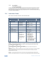
8.1
Setting the Configuration DIP-switch
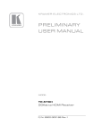
The 8x dip-switch provides the ability to configure a number of device functions. A
switch that is down is on, a switch that is up is off. By default, switch 2 is down
(on), all the other switches are up (off).
Figure 8: The Configuration DIP-switch
Note: You must power cycle the device if you make any changes to the
DIP-switch.
#
Feature
Function
DIP-switch
1
Program
Enables firmware updates
On—Enable updating
Off—Disable updating
2
General Audio
Control
Selects whether the analog
audio is embedded in the
outputs, (see Section 6.2)
On—Use embedded audio for
HDMI and DP; the audio selection
for DVI is selected by DIP-switch 3
Off—The HDMI, DVI and DP
inputs use the analog audio signal
if a 3.5mm audio jack is inserted
into the analog audio input. If no
jack is inserted, they use their
embedded audio signals
3
DVI Audio
Control
(active only
when DIPswitch 2 is on)
Selects whether the analog
audio is embedded in the DVI
signal
On—When switch #2 is on, the
analog audio signal is used with
the DVI input
Off—When switch #2 is off, the
embedded audio signal is used in
the DVI input
4
Video Mode
Input Selection
Sets the video input selection
mode to either last connected or
manual
On—Last connected
Off—Manual
5
Lock EDID
Locks the current EDID, (see
Section 7.3)
On—Locked EDID
Off—Automatic EDID selection
16
SID-X3N - Configuring the SID-X3N
#
Feature
Function
DIP-switch
6
Switching Delay
Selects the time delay before
switching occurs when an input
cable is removed.
Note: When the input sync is lost
but the cable is not removed, the
delay is always six seconds
When the input signal is lost but
the cable is not removed:
On—0.5 seconds
Off—10 seconds
When the cable is removed:
On—0.5 seconds
Off—3 seconds
7
Output Power
Shutdown Delay
Sets the delay time between loss
of the input signal and output
power shutdown
On—1 minute
Off—15 minutes
8
Output Power
Control
Enables/disables the output
power when the input signal is
lost
On—Power is always on
Off—Power is disabled when input
signal is lost after delay set by
DIP-switch 7
Note: DIP-switch 2 must be set to ON to enable DIP-switch 3 to control the DVI
audio mode selection.
SID-X3N - Configuring the SID-X3N
17
9
Technical Specifications
INPUTS:
OUTPUTS:
PORTS:
18
Video:
1 HDMI on an HDMI connector
1 DP on a DisplayPort connector
1 DVI-D on a DVI-I connector
1 VGA on a 15-pin HD (F) connector
Audio:
1 Unbalanced stereo audio on a 3.5mm mini jack
1 HDMI on an HDMI connector
1 Unbalanced stereo audio in a 3.5mm mini jack
1 RS-232 3-pin terminal block for programming
1 USB Power. Max 1.5A
CONTROLS:
Front panel buttons, remote step-in switch, remote input
selection switches, RS-232
ANALOG AUDIO
INPUT:
Maximum level—3Vpp
REMOTE LED
IMPEDANCE:
5V, 300Ω approx.
STANDARDS:
HDMI with Deep Color, x.v.Color™ and 3D
HDCP: Works with sources that support HDCP repeater mode
POWER
CONSUMPTION:
COMPLIANCE
STANDARDS:
OPERATING
TEMPERATURE:
STORAGE
TEMPERATURE:
HUMIDITY:
COOLING:
ENCLOSURE TYPE:
DIMENSIONS:
12V DC, 1.1A
WEIGHT:
0.48kg (1.1lbs) approx.
INCLUDED
ACCESSORIES:
OPTIONS:
Power adapter
CE, UL
0° to +40°C (32° to 104°F)
–40° to +70°C (–40° to 158°F)
10% to 90%, RHL non-condensing
Convection, vents
Aluminium
18.8cm x 11.3cm x 2.5cm (7.4” x 4.5” x 1”) W, D, H
19“ Rack adapter RK-T2B, RTBUS-12, RTBUS-22, SID-X3NBP
Kit (substitute a black top plate for the SID-X3N to blend in with
the color of the modular TBUS-10xl)
SID-X3N - Technical Specifications
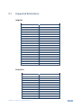
9.1
Supported Resolutions
HDMI/DVI
Resolution
Refresh Rate
640 x 480p
85Hz; 75Hz; 72Hz; 60Hz; 59.95Hz
720 x 480i
30Hz
720 x 480p
60Hz
720 x 576p
50Hz
800 x 600p
85Hz; 75Hz; 72Hz; 60Hz
848 x 480p
60Hz
852 x 480p
60Hz
1024 x 768p
85Hz; 75Hz; 70Hz; 60Hz
1080 x 1920p
50Hz; 60Hz; 24Hz;
1080 x 1920i
50Hz; 60Hz;
1152 x 864p
75Hz
1280 x 768p
60Hz
1280 x 800p
60Hz
1280 x 960
60Hz
1280 x 1024p
75Hz; 60Hz
1360 x 768p
60Hz
1366 x 768
60Hz; 50Hz
1400 x 1050p
60Hz
1440 x 900p
60Hz
1600 x 900p
60Hz
1600 x 1200p
60Hz
1680 x 1050p
60Hz
DisplayPort
Resolution
Refresh Rate
640 x 480p
85Hz; 75Hz; 72Hz; 60Hz
800 x 600p
85Hz; 75Hz; 72Hz; 60Hz
848 x 480p
60Hz
1024 x 768p
85Hz; 75Hz; 70Hz; 60Hz
1080 x 1920i
60Hz;
1152 x 864p
75Hz
1280 x 768p
60Hz
1280 x 800p
60Hz
1280 x 960
60Hz
1280 x 1024p
75Hz; 60Hz
1360 x 768p
60Hz
1366 x 768
60Hz;
1400 x 1050
60Hz
SID-X3N - Technical Specifications
19
Resolution
Refresh Rate
1440 x 900p
60Hz
1600 x 900p
60Hz
1600 x 1200p
60Hz
1680 x 1050p
60Hz
VGA
Resolution
20
Refresh Rate
640 x 480p
60Hz
720 x 480p
60Hz
800 x 600p
60Hz
1024 x 768p
60Hz
1152 x 864
75Hz
1280 x 720p
60Hz; 50Hz
1280 x 960p
60Hz
1280 x 1024p
60Hz
1360 x 768
60Hz;
1366 x 768
60Hz; 50Hz
1400 x 1050
60Hz
1440 x 900
60Hz
1920 x 1080p
60Hz
1920 x 1200
60Hz; 50Hz
SID-X3N - Technical Specifications
10
Default EDID
Each input on the SID-X3N is loaded with a factory default EDID.
Note: When the SID-X3N is connected to a DVI acceptor, audio block is added to
the EDID.
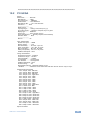
10.1
HDMI, DisplayPort and DVI
Monitor
Model name............... SID-X3N
Manufacturer............. KMR
Plug and Play ID......... KMR0672
Serial number............ 505-709990100
Manufacture date......... 2011, ISO week 255
Filter driver............ None
------------------------EDID revision............ 1.3
Input signal type........ Digital
Color bit depth.......... Undefined
Display type............. RGB color
Screen size.............. 520 x 320 mm (24.0 in)
Power management......... Standby, Suspend, Active off/sleep
Extension blocs.......... 1 (CEA-EXT)
------------------------DDC/CI................... n/a
Color characteristics
Default color space...... Non-sRGB
Display gamma............ 2.20
Red chromaticity......... Rx 0.674 - Ry 0.319
Green chromaticity....... Gx 0.188 - Gy 0.706
Blue chromaticity........ Bx 0.148 - By 0.064
White point (default).... Wx 0.313 - Wy 0.329
Additional descriptors... None
Timing characteristics
Horizontal scan range.... 30-83kHz
Vertical scan range...... 56-76Hz
Video bandwidth.......... 170MHz
CVT standard............. Not supported
GTF standard............. Not supported
Additional descriptors... None
Preferred timing......... Yes
Native/preferred timing.. 1280x720p at 60Hz (16:10)
Modeline............... "1280x720" 74.250 1280 1390 1430 1650 720 725 730 750 +hsync +vsync
Standard timings supported
720 x 400p at 70Hz - IBM VGA
720 x 400p at 88Hz - IBM XGA2
640 x 480p at 60Hz - IBM VGA
640 x 480p at 67Hz - Apple Mac II
640 x 480p at 72Hz - VESA
640 x 480p at 75Hz - VESA
800 x 600p at 56Hz - VESA
800 x 600p at 60Hz - VESA
800 x 600p at 72Hz - VESA
800 x 600p at 75Hz - VESA
832 x 624p at 75Hz - Apple Mac II
1024 x 768i at 87Hz - IBM
1024 x 768p at 60Hz - VESA
1024 x 768p at 70Hz - VESA
1024 x 768p at 75Hz - VESA
1280 x 1024p at 75Hz - VESA
SID-X3N - Default EDID
21
1152 x 870p at 75Hz - Apple Mac II
1280 x 1024p at 75Hz - VESA STD
1280 x 1024p at 85Hz - VESA STD
1600 x 1200p at 60Hz - VESA STD
1024 x 768p at 85Hz - VESA STD
800 x 600p at 85Hz - VESA STD
640 x 480p at 85Hz - VESA STD
1152 x 864p at 70Hz - VESA STD
1280 x 960p at 60Hz - VESA STD
EIA/CEA-861 Information
Revision number.......... 3
IT underscan............. Supported
Basic audio.............. Supported
YCbCr 4:4:4.............. Supported
YCbCr 4:2:2.............. Supported
Native formats........... 1
Detailed timing #1....... 1920x1080p at 60Hz (16:10)
Modeline............... "1920x1080" 148.500 1920 2008 2052 2200 1080 1084 1089 1125 +hsync +vsync
Detailed timing #2....... 1920x1080i at 60Hz (16:10)
Modeline............... "1920x1080" 74.250 1920 2008 2052 2200 1080 1084 1094 1124 interlace +hsync
+vsync
Detailed timing #3....... 1280x720p at 60Hz (16:10)
Modeline............... "1280x720" 74.250 1280 1390 1430 1650 720 725 730 750 +hsync +vsync
Detailed timing #4....... 720x480p at 60Hz (16:10)
Modeline............... "720x480" 27.000 720 736 798 858 480 489 495 525 -hsync -vsync
CE video identifiers (VICs) - timing/formats supported
1920 x 1080p at 60Hz - HDTV (16:9, 1:1)
1920 x 1080i at 60Hz - HDTV (16:9, 1:1)
1280 x 720p at 60Hz - HDTV (16:9, 1:1) [Native]
720 x 480p at 60Hz - EDTV (16:9, 32:27)
720 x 480p at 60Hz - EDTV (4:3, 8:9)
720 x 480i at 60Hz - Doublescan (16:9, 32:27)
720 x 576i at 50Hz - Doublescan (16:9, 64:45)
640 x 480p at 60Hz - Default (4:3, 1:1)
NB: NTSC refresh rate = (Hz*1000)/1001
CE audio data (formats supported)
LPCM 2-channel, 16/20/24 bit depths at 32/44/48 kHz
CE vendor specific data (VSDB)
IEEE registration number. 0x000C03
CEC physical address..... 1.0.0.0
Maximum TMDS clock....... 165MHz
CE speaker allocation data
Channel configuration.... 2.0
Front left/right......... Yes
Front LFE................ No
Front center............. No
Rear left/right.......... No
Rear center.............. No
Front left/right center.. No
Rear left/right center... No
Rear LFE................. No
Report information
Date generated........... 11/08/2014
Software revision........ 2.60.0.972
Data source.............. File
Operating system......... 6.1.7601.2.Service Pack 1
Raw data
00,FF,FF,FF,FF,FF,FF,00,2D,B2,72,06,02,00,00,00,FF,15,01,03,80,34,20,78,EA,B3,25,AC,51,30,B4,26,
10,50,54,FF,FF,80,81,8F,81,99,A9,40,61,59,45,59,31,59,71,4A,81,40,01,1D,00,72,51,D0,1E,20,6E,28,
55,00,07,44,21,00,00,1E,00,00,00,FF,00,35,30,35,2D,37,30,39,39,39,30,31,30,30,00,00,00,FC,00,53,
49,44,2D,58,33,4E,00,00,00,00,00,00,00,00,00,FD,00,38,4C,1E,53,11,00,0A,20,20,20,20,20,20,01,30,
02,03,1B,F1,48,10,05,84,03,02,07,16,01,23,09,07,07,65,03,0C,00,10,00,83,01,00,00,02,3A,80,18,71,
38,2D,40,58,2C,45,00,07,44,21,00,00,1E,01,1D,80,18,71,1C,16,20,58,2C,25,00,07,44,21,00,00,9E,01,
1D,00,72,51,D0,1E,20,6E,28,55,00,07,44,21,00,00,1E,8C,0A,D0,8A,20,E0,2D,10,10,3E,96,00,07,44,21,
22
SID-X3N - Default EDID
00,00,18,00,00,00,00,00,00,00,00,00,00,00,00,00,00,00,00,00,00,00,00,00,00,00,00,00,00,00,00,47
10.2
PC-UXGA
Monitor
Model name............... SID-X3N
Manufacturer............. KMR
Plug and Play ID......... KMR0672
Serial number............ 505-709990100
Manufacture date......... 2011, ISO week 255
Filter driver............ None
------------------------EDID revision............ 1.3
Input signal type........ Analog 0.700,0.000 (0.7V p-p)
Sync input support....... Separate, Composite, Sync-on-green
Display type............. RGB color
Screen size.............. 520 x 320 mm (24.0 in)
Power management......... Standby, Suspend, Active off/sleep
Extension blocs.......... None
------------------------DDC/CI................... n/a
Color characteristics
Default color space...... sRGB
Display gamma............ 2.20
Red chromaticity......... Rx 0.674 - Ry 0.319
Green chromaticity....... Gx 0.188 - Gy 0.706
Blue chromaticity........ Bx 0.148 - By 0.064
White point (default).... Wx 0.313 - Wy 0.329
Additional descriptors... None
Timing characteristics
Horizontal scan range.... 30-83kHz
Vertical scan range...... 56-76Hz
Video bandwidth.......... 170MHz
CVT standard............. Not supported
GTF standard............. Not supported
Additional descriptors... None
Preferred timing......... Yes
Native/preferred timing.. 1280x720p at 60Hz (16:10)
Modeline............... "1280x720" 74.250 1280 1390 1430 1650 720 725 730 750 +hsync +vsync
Standard timings supported
720 x 400p at 70Hz - IBM VGA
720 x 400p at 88Hz - IBM XGA2
640 x 480p at 60Hz - IBM VGA
640 x 480p at 67Hz - Apple Mac II
640 x 480p at 72Hz - VESA
640 x 480p at 75Hz - VESA
800 x 600p at 56Hz - VESA
800 x 600p at 60Hz - VESA
800 x 600p at 72Hz - VESA
800 x 600p at 75Hz - VESA
832 x 624p at 75Hz - Apple Mac II
1024 x 768i at 87Hz - IBM
1024 x 768p at 60Hz - VESA
1024 x 768p at 70Hz - VESA
1024 x 768p at 75Hz - VESA
1280 x 1024p at 75Hz - VESA
1152 x 870p at 75Hz - Apple Mac II
1280 x 1024p at 75Hz - VESA STD
1280 x 1024p at 85Hz - VESA STD
1600 x 1200p at 60Hz - VESA STD
1024 x 768p at 85Hz - VESA STD
800 x 600p at 85Hz - VESA STD
640 x 480p at 85Hz - VESA STD
1152 x 864p at 70Hz - VESA STD
1280 x 960p at 60Hz - VESA STD
Report information
SID-X3N - Default EDID
23
Date generated........... 11/08/2014
Software revision........ 2.60.0.972
Data source.............. File
Operating system......... 6.1.7601.2.Service Pack 1
Raw data
00,FF,FF,FF,FF,FF,FF,00,2D,B2,72,06,02,00,00,00,FF,15,01,03,6E,34,20,78,EE,B3,25,AC,51,30,B4,26,
10,50,54,FF,FF,80,81,8F,81,99,A9,40,61,59,45,59,31,59,71,4A,81,40,01,1D,00,72,51,D0,1E,20,6E,28,
55,00,07,44,21,00,00,1E,00,00,00,FF,00,35,30,35,2D,37,30,39,39,39,30,31,30,30,00,00,00,FC,00,53,
49,44,2D,58,33,4E,00,00,00,00,00,00,00,00,00,FD,00,38,4C,1E,53,11,00,0A,20,20,20,20,20,20,00,3F,
FF,FF,FF,FF,FF,FF,FF,FF,FF,FF,FF,FF,FF,FF,FF,FF,FF,FF,FF,FF,FF,FF,FF,FF,FF,FF,FF,FF,FF,FF,FF,FF,
FF,FF,FF,FF,FF,FF,FF,FF,FF,FF,FF,FF,FF,FF,FF,FF,FF,FF,FF,FF,FF,FF,FF,FF,FF,FF,FF,FF,FF,FF,FF,FF,
FF,FF,FF,FF,FF,FF,FF,FF,FF,FF,FF,FF,FF,FF,FF,FF,FF,FF,FF,FF,FF,FF,FF,FF,FF,FF,FF,FF,FF,FF,FF,FF,
FF,FF,FF,FF,FF,FF,FF,FF,FF,FF,FF,FF,FF,FF,FF,FF,FF,FF,FF,FF,FF,FF,FF,FF,FF,FF,FF,FF,FF,FF,FF,FF
24
SID-X3N - Default EDID
11
Protocol 2000
Note: The SID-X3N can receive P2000 commands over HDMI only from the
VP-81SID.
This RS-232/RS-485 communication protocol uses four bytes of information as
defined below.
For RS-232, a null-modem connection between the machine and controller is
used. The default data rate is 9600 baud, with no parity, 8 data bits and 1 stop bit.
Note: Compatibility with Kramer’s Protocol 2000 does not mean that a machine
uses all of the commands below. Each machine uses a sub-set of Protocol 2000,
according to its needs.
11.1
Syntax
MSB
LSB
1st Byte
0
7
DESTINATION
D
6
INSTRUCTION
N2
2
N5
5
N4
4
N3
3
2nd Byte
1
7
I6
6
I5
5
I4
4
INPUT
I3
3
3rd Byte
1
7
O6
6
O5
5
O4
4
OUTPUT
O3
3
4th Byte
1
7
OVR
6
X
5
M4
4
M3
3
N1
1
N0
0
I2
2
I1
1
I0
0
O2
2
O1
1
O0
0
MACHINE NUMBER
M2
M1
2
1
M0
0
Bit 7 – Defined as 0
D – DESTINATION:
0 – Sends information to the switchers (from the PC)
1 – Sends information to the PC (from the switcher)
N5…N0 – INSTRUCTION
The 6-bit INSTRUCTION defines the function performed by the switcher(s). If a function is performed using the
machine’s keyboard, these bits are set with the INSTRUCTION NO. performed. The instruction codes are defined
according to the table below (INSTRUCTION NO. is the value set in N5…N0).
1st Byte:
Bit 7 – Defined as 1
I6…I0 – INPUT
When switching (i.e. instruction codes 1 and 2), the 7-bit INPUT is set as the input number to be switched. If switching is
done using the machine’s front panel, these bits are set with the INPUT NUMBER switched. For other operations, these
bits are defined according to the table.
2nd Byte:
Bit 7 – Defined as 1
O6…O0 – OUTPUT
When switching (i.e. instruction codes 1 and 2), the 7-bit OUTPUT is set as the output number to be switched. If
switching is done using the machine’s front panel, these bits are set with the OUTPUT NUMBER switched. For other
operations, these bits are defined according to the table.
3rd Byte:
SID-X3N - Protocol 2000
25
Bit 7 – Defined as 1
Bit 5 – Don’t care
OVR – Machine number override
M4…M0 – MACHINE NUMBER
This byte is used to address machines in a system by their machine numbers. When several machines are controlled
from a single serial port, they are usually configured together and each machine has an individual machine number. If
the OVR bit is set, then all machine numbers accept (implement) the command and the addressed machine replies.
When a single machine is controlled over the serial port, always set M4…M0 to 1, and make sure that the machine itself
is configured as MACHINE NUMBER = 1.
4th Byte:
11.2
Instruction Codes
All the values in the table are decimal, unless otherwise stated
Instruction Codes for Protocol 2000
#
0
1
2
3
4
5
6
7
Instruction
Description
Definition for Specific Instruction
Input
Output
RESET VIDEO
SWITCH VIDEO
0
Set equal to video input
that is switched
(0 = disconnect)
SWITCH AUDIO
Set equal to audio input
that is switched
(0 = disconnect)
STORE VIDEO STATUS Set as SETUP #
RECALL VIDEO
STATUS
REQUEST STATUS OF
A VIDEO OUTPUT
REQUEST STATUS OF
AN AUDIO OUTPUT
VIS SOURCE
Set as SETUP #
Set as SETUP #
Set as SETUP #
Set as input # when
OUTPUT byte = 6;
OR
Set as output # when
OUTPUT byte = 7;
OR
Set as blank period
(in steps of 25ms) when
OUTPUT byte = 32;
OR
Set = 0. *****
Notes
0
Set equal to video output that is
switched
(0 = to all the outputs)
Set equal to audio output that is
switched
(0 = to all the outputs)
To store
To delete
0
1
2, 15
Equal to output number whose
status is required
Equal to output number whose
status is required
0 – No VIS (immediate)
1 – Input # 1
2 – External digital sync
3 – External analog sync
4 – Dynamic sync
5 – Inter-machine sync
6 – Input # (INPUT byte)
7 – Output #(INPUT byte)
8 – User-defined sync
32 – RGBHV seamless switching
64 – Set for delayed switch
65 – Execute delayed switch
66 – Cancel delayed switch
setting
4, 3
2
2, 3, 15
2, 3, 15
4, 3
2, 5, 17, 18
NOTES on the above table:
NOTE 2 – These are bi-directional definitions. If the switcher receives the code, it performs the instruction. If
the instruction is performed (due to a keystroke operation on the front panel), then these codes are sent.
For example, if the PC sends HEX code:
01
85
88
83
then the switcher (machine 3) switches input 5 to output 8.
If the user switches input 1 to output 7 using the front panel buttons, the switcher sends HEX code:
41
81
87
83
to the PC.
When the PC sends one of the commands in this group to the switcher, if the instruction is valid, the switcher
replies by sending the same four bytes to the PC that it received (except for the first byte, where the
DESTINATION bit is set high).
NOTE 5 – For the OUTPUT byte set as 6, the VIS source is the input selected using the OUTPUT byte.
Similarly, for the OUTPUT byte set as 7, the VIS source is the output selected using the OUTPUT byte. Note
26
SID-X3N - Protocol 2000
that on some machines the sync source is not software selectable, but is selected using switches, jumpers,
etc.
NOTE 17 – For clean switching of RGBHV video, the seamless switching option can be used. The blanking
period for the transition of the RGB sources can be set in steps of 25 milliseconds.
For example, to set for 350ms blanking time (14 steps), send HEX code:
07
8E
A0
81.
NOTE 18 – Delayed execution switches after a delay dictated by RS-232 control. To do this, the user sends
instruction 7 with the SET FOR DELAYED SWITCH option (64 dec) before sending the switch command
(instruction 1) or pressing a front panel button. The switch is not executed (unless timed-out) until the
EXECUTE DELAYED SWITCH code is sent, or the SET FOR DELAYED SWITCH code is sent again. (The
mode is automatically cancelled after switching if the EXECUTE command is used).
For example, to connect input 4 to output 3 after a delay, send HEX code:
07
80
C0
81 (set for delayed switch)
01
84
83
81 (switch code)
then, after the required delay, send HEX code:
07
80
C1
81(execute delayed switch)
to implement the switch.
The following sources are supported:
HDMI input :
DP input :
DVI input :
VGA input :
0x07 0x80 0x81 0x81<CR>
0x07 0x80 0x85 0x81<CR>
0x07 0x80 0x89 0x81<CR>
0x07 0x80 0x8C 0x81<CR>
SID-X3N - Protocol 2000
27
12
Protocol 3000
Note: The SID-X3N can be operated using serial commands issued by a remote
device and which are received over the HDBT/DGKat link.
This section describes:
12.1
Kramer Protocol 3000 syntax (see Section 12.1)
Kramer Protocol 3000 commands (see Section 12.2)
Kramer Protocol 3000 Syntax
12.1.1
Host Message Format
Start
Address (optional)
Body
Delimiter
#
Destination_id@
Message
CR
12.1.1.1
Simple Command
Command string with only one command without addressing:
Start
Body
Delimiter
#
Command SP Parameter_1,Parameter_2,…
CR
12.1.1.2
Command String
Formal syntax with commands concatenation and addressing:
Start
Address
Body
Delimiter
#
Destination_id@
Command_1 Parameter1_1,Parameter1_2,…|
Command_2 Parameter2_1,Parameter2_2,…|
Command_3
Parameter3_1,Parameter3_2,…|…
CR
12.1.2
Device Message Format
Start
Address (optional)
Body
delimiter
~
Sender_id@
Message
CR LF
12.1.2.1
Device Long Response
Echoing command:
Start
Address (optional)
Body
Delimiter
~
Sender_id@
Command SP [Param1 ,Param2 …] result
CR LF
CR = Carriage return (ASCII 13 = 0x0D)
LF = Line feed (ASCII 10 = 0x0A)
28
SID-X3N - Protocol 3000
SP = Space (ASCII 32 = 0x20)
12.1.3
Command Terms
Command
A sequence of ASCII letters ('A'-'Z', 'a'-'z' and '-').
Command and parameters must be separated by at least one space.
Parameters
A sequence of alphanumeric ASCII characters ('0'-'9','A'-'Z','a'-'z' and some special
characters for specific commands). Parameters are separated by commas.
Message string
Every command entered as part of a message string begins with a message
starting character and ends with a message closing character.
Note: A string can contain more than one command. Commands are separated by
a pipe ( '|' ) character.
Message starting character
'#' – For host command/query
'~' – For device response
Device address (Optional, for K-NET)
K-NET Device ID followed by '@'
Query sign
'?' follows some commands to define a query request.
Message closing character
CR – For host messages; carriage return (ASCII 13)
CRLF – For device messages; carriage return (ASCII 13) + line-feed (ASCII 10)
Command chain separator character
When a message string contains more than one command, a pipe ( '|' ) character
separates each command.
Spaces between parameters or command terms are ignored.
SID-X3N - Protocol 3000
29
12.1.4
Entering Commands
You can directly enter all commands using a terminal with ASCII communications
software, such as HyperTerminal, Hercules, etc. Connect the terminal to the serial
or Ethernet port on the Kramer device. To enter CR press the Enter key.
( LF is also sent but is ignored by command parser).
For commands sent from some non-Kramer controllers, (for example, Crestron)
some characters require special coding (such as, /X##). Refer to the controller
manual.
12.1.5
Command Forms
Some commands have short name syntax in addition to long name syntax to allow
faster typing. The response is always in long syntax.
12.1.6
Chaining Commands
Multiple commands can be chained in the same string. Each command is
delimited by a pipe character (“|”). When chaining commands, enter the message
starting character and the message closing character only once, at the
beginning of the string and at the end.
Commands in the string do not execute until the closing character is entered. A
separate response is sent for every command in the chain.
12.1.7
Maximum String Length
64 characters
30
SID-X3N - Protocol 3000
12.2
Kramer Protocol 3000 Commands
The following table lists the Protocol 3000 commands that the SID-X3N supports.
For a full description of the commands, see the Kramer Protocol 3000 document
available from http://www.kramerelectronics.com.
Note: The SID-X3N can only receive commands from a device, (for example, an
HDBT receiver) via the HDBaseT link, and only at 9600bps.
Command
Description
#
Protocol handshaking
MODEL?
Read device model
STEPIN-CP?
Get module Step-in capabilities
VID
Set video switch
VID?
Get video switch status
Command - MODEL?
Command Name
Command Type - System-mandatory
Permission
Transparency
Set:
-
-
-
Get:
MODEL?
End User
Public
Description
Syntax
Set:
-
-
Get:
Get device model
#MODEL?␍
Response
~nn@MODEL␠model_name␍␊
Parameters
model_name - String of up to 19 printable ASCII chars
Response Triggers
Notes
SID-X3N - Protocol 3000
31
Command – STEPIN-CP
Command Type – (ROUTING)
Command Name
Permission
Transparency
End User
Public
Set:
none
Get:
STEPIN-CP?
Description
Set:
None
Get:
Get module STEP-IN
capabilities
Syntax
# STEPIN-CP? ␍
Response
~ nn @ STEPIN-CP ␠ capabilities, num_of_inputs, num_of_cntl_btn ␍␊
Parameters
capabilities – 1- module support STEP-IN
0 – module doesn’t support STEP-IN
num_of_inputs – number of video inputs for remote switching
num_of_cntl_btn – number of control buttons, to be programmed in Master device
Response Triggers
Notes
If module doesn’t support STEP-IN it might answer with error “command not supported”
32
SID-X3N - Protocol 3000
Command - VID
Command Name
Command Type - Switch
Permission
Transparency
Set:
VID
End User
Public
Get:
VID?
End User
Public
Description
Syntax
Set:
Set video switch state
Get:
Get video switch state
#VID␠in>out, in>out,…␍
#VID?␠out␍
#VID?␠ * ␍
Response
Set: ~nn@VID␠in>out ␍␊
~nn@VID␠in>out ␍␊ …
Get: ~nn@VID␠in>out ␍␊
~nn@VID␠in>1, in>2, … ␍␊
Parameters
in - input number or '0' to disconnect output
> - connection character between in and out parameters
out - output number or '*' for all outputs
Response Triggers
Notes
When AFV switching mode is active, this command also switches audio and the unit replies with
command ~AV.
Examples
When AFV switching mode is active, this command also switches audio and the unit replies with
command ~AV.
Switch video and audio input 3 to output 7
#AV 3>7CR
~01@AV 3>7CRLF
Switch video input 2 to output 4
#V 2>4CR
~01@VID 2>4CRLF
Switch video input 4 to output 2 in machine
6
#6@VID 4>2CR
~06@VID 4>2CRLF
Disconnect video and audio output 4
#AV 0>4CR
~01@AV 0>4CRLF
Switch video input 3 to all outputs
#V 3>* CR
~01@VID 3>* CRLF
Chaining
multiple
commands
#AV 1>* | V 3>4, 2>2, 2>1, 0>2 | V 3>9 | A 0>1 | V? *
CR
1. Switch audio and video from input 1 to all outputs
2. Switch video input 3 to output 4,
video input 2 to output 2,
video input 2 to output 1 and
disconnect video output 2
3. Switch video input 3 to output 9 (non-existent)
4. Disconnect audio output 1
5. Get status of all video links
Command processing begins after entering CR
A response is sent for each command after processing
SID-X3N - Protocol 3000
~AV 1>*CRLF
~VID 3>4 CRLF
~VID 2>2 CRLF
~VID 2>1 CRLF
~VID 0>2 CRLF
~VID ERR003 CRLF
~AUD 0>1CRLF
~VID 2>1, 0>2, 1>3,
3>4 CRLF
33
For the latest information on our products and a list of Kramer distributors, visit
our Web site where updates to this user manual may be found.
We welcome your questions, comments, and feedback.
Web site: www.kramerelectronics.com
E-mail: [email protected]
!
P/N:
SAFETY WARNING
Disconnect the unit from the power
supply before opening and servicing
2900- 300304
Rev: 3