1
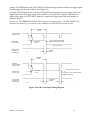
A single TTL HIGH pulse at the GATE INPUT equal to the trigger period will allow one trigger signal
from the trigger stream to be enabled. (See Figure 4A)
If a single TTL HIGH pulse arrives at the GATE INPUT and is equal to twice the trigger period, two
trigger signals from the trigger stream will be enabled. (See Figure 4B) Therefore, the number of
trigger pulses input (or GATE INPUT duration) is equal to the trigger period times the number of
exposures desired.
Please note: The VMM-T1 TRIGGER INPUT triggers the internal timers. The EXP PRESET will
determine the number of cycles which is the combination of EXPOSURE and DELAY time.
TRIGGER
PERIOD
TRIGGER
SIGNAL STREAM
(ACTIVE LOW)
HIGH GATE
PULSE
GATE SIGNAL
(ACTIVE HIGH)
ACTIVE HIGH PULSE WIDTH
EQUAL TO TRIGGER PERIOD
LOW GATE PULSE
SINGLE PULSE
ALLOWED TO
TRIGGER UNIT
TRIGGER
PULSE
(A)
TRIGGER
PERIOD
TRIGGER
SIGNAL STREAM
(ACTIVE LOW)
ACTIVE HIGH PULSE WIDTH
HIGH GATE
PULSE
GATE SIGNAL
(ACTIVE HIGH)
EQUAL TO 2X TRIGGER PERIOD
LOW GATE PULSE
TWO PULSES
ALLOWED TO
TRIGGER UNIT
2 TRIGGER
PULSES
(B)
Figure 4A & 4B: Gate Input Timing Diagram
VMM-T1 User Manual
24