1
SVENSKA
ITALIANO
ESPAÑOL
NEDERLANDS
DEUTSCH
FRANÇAIS
ENGLISH
AV Surround Receiver
SR6003
SR6003_N_00_cover.indd 3
08.7.30 3:24:07 PM
ENGLISH
NEDERLANDS
WARRANTY
For warranty information, contact your local Marantz
distributor.
GARANTIE
Voor inlichtingen omtrent garantie dient u zich tot uw
plaatselijke Marantz.
RETAIN YOUR PURCHASE RECEIPT
Your purchase receipt is your permanent record of a
valuable purchase. It should be kept in a safe place
to be referred to as necessary for insurance purposes
or when corresponding with Marantz.
UW KWITANTIE, KASSABON E.D. BEWAREN
Uw kwitantie, kassabon e.d. vormen uw bewijs van
aankoop van een waardevol artikel en dienen op een
veilige plaats bewaard te worden voor evt, verwijzing
bijv, in verbend met verzekering of bij correspondentie
met Marantz.
IMPORTANT
When seeking warranty service, it is the responsibility of
the consumer to establish proof and date of purchase.
Your purchase receipt or invoice is adequate for such
proof.
FOR U.K. ONLY
This undertaking is in addition to a consumer's
statutory rights and does not affect those rights in
any way.
FRANÇAIS
GARANTIE
Pour des informations sur la garantie, contacter le
distributeur local Marantz.
CONSERVER L'ATTESTATION D'ACHAT
L'attestation d'achat est la preuve permanente
d'un achat de valeur. La conserver en lieu sur pour
s'y reporter aux fins d'obtention d'une couverture
d'assurance ou dans le cadre de correspondances
avec Marantz.
IMPORTANT
Pour l'obtention d'un service couvert par la garantie,
il incombe au client d'établir la preuve de l'achat
et d'en corroborer la date. Le reçu ou la facture
constituent des preuves suffisantes.
DEUTSCH
BELANGRIJK
Bij een evt, beroep op de garantie is het de
verantwoordelijkheid van de consument een
gedateerd bewijs van aankoop te tonen. Uw
kassabon of factuurzijn voldoende bewijs.
ESPAÑOL
GARANTIA
Para obtener información acerca de la garantia
póngase en contacto con su distribuidor Marantz.
GUARDE SU RECIBO DE COMPRA
Su recibo de compra es su prueba permanente de
haber adquirido un aparato de valor, Este recibo
deberá guardarlo en un lugar seguro y utilizarlo
como referencia cuando tenga que hacer uso del
seguro o se ponga en contacto con Marantz.
IMPORTANTE
Cuando solicite el servicio otorgado por la garantia
el usuario tiene la responsabilidad de demonstrar
cuándo efectuó la compra. En este caso, su recibo
de compra será la prueba apropiada.
ITALIANO
GARANZIA
L’apparecchio è coperto da una garanzia di buon
funzionamento della durata di un anno, o del periodo
previsto dalla legge, a partire dalla data di acquisto
comprovata da un documento attestante il nominativo
del Rivenditore e la data di vendita. La garanzia sarà
prestata con la sostituzione o la riparazione gratuita
delle parti difettose.
Non sono coperti da garanzia difetti derivanti da
uso improprio, errata installazione, manutenzione
effettuata da personale non autorizzato o, comunque,
da circostanze che non possano riferirsi a difetti di
funzionamento dell’apparecchio. Sono inoltre esclusi
dalla garanzia gli interventi inerenti l’installazione e
l’allacciamento agli impianti di alimentazione.
Gli apparecchi verranno riparati presso i nostri Centri
di Assistenza Autorizzati. Le spese ed i rischi di
trasporto sono a carico del cliente.
La casa costruttrice declina ogni responsabilità per
danni diretti o indiretti provocati dalla inosservanza
delle prescrizioni di installazione, uso e manutenzione
dettagliate nel presente manuale o per guasti dovuti ad
uso continuato a fini professionali.
SVENSKA
GARANTI
För information om garantin, kontakta Marantz
lokalagent.
SPAR KVITTOT
Kvittot är ett inköpsbevis på en värdefull vara. Det skall
förvaras säkert och hänvisas till vid försäkringsfall
eller vidkorrespondens mod Marantz.
VIKTIGT
Fö att garantin skall gälla är det kundens sak att
framställa bevis och datum om köpet. Kvitto eller
faktura är tillräokligt bevis fö detta.
GARANTIE
Bei Garantiefragen wenden Sie sich bitte an Ihren
Marantz-Händler.
HEBEN SIE IHRE QUITTING GUT AUF
Die Quittung dient Ihnen als bleibende Unterlage
für Ihren wertvollen Einkauf Das Aufbewahren der
Quittung ist wichtig, da die darin enthaltenen Angaben
für Versicherungswecke oder bei Korrespondenz mit
Marantz angeführt werden müssen.
WICHTIG!
Bei Garantiefragen muß der Kunde eine Kaufunterlage
mit Kaufdatum vorlegen. Ihren Quittung oder
Rechnung ist als Unterlage ausreichend.
SR6003_N_00_cover.indd 4
08.7.30 3:24:07 PM
English
Français
Deutsch
Italiano
WARNINGS
- Do not expose the equipment to rain, moisture,
dripping or splashing.
- Do not remove the cover from the equipment.
- Do not insert anything into the equipment through
the ventilation holes.
- Do not handle the mains cord with wet hands.
- Do not cover the ventilation with any items such as
tablecloths, newspapers, curtains, etc.
- No naked flame sources, such as lighted candles,
should be placed on the equipment.
- When disposing of used batteries, please comply
with governmental regulations or environmental
public instruction’s rules that apply in your country
or area.
- Make a space of about 0.2 meter around the unit.
- No objects filled with liquids, such as vases, shall
be placed on the equipment.
- When the switch is in the OFF position, the
equipment is not completely switched off from
MAINS.
- The equipment shall be installed near the
power supply so that the power supply is easily
accessible.
Il SR6003 è conforme alle direttive CEE
ed a quelle per i bassi voltaggi.
- Do not touch hot areas, especially around the “hot
surface mark” during and immediately after use.
- During and immediately after use, this product
is hot in areas other than the controls and rear
panel connection jacks. Do not touch hot areas,
especially around the “hot surface mark” and
the top panel. Contact with hot areas can cause
burns.
WARNHINWEISE
- Das Gerät nicht Regen, Feuchtigkeit, Tropf- oder
Spritzwasser aussetzen.
- Die Abdeckung nicht vom Gerät abnehmen.
- Keine Gegenstände durch die Belüftungsschlitze
stecken.
- Das Netzkabel nicht mit feuchten oder nassen
Händen anfassen.
- Decken Sie die Lüftungsöffnungen nicht mit einem
Tischtuch, einer Zeitung, einem Vorhang usw. ab.
- Es dürfen keine Gegenstände mit offener Flamme,
wie etwa brennende Kerzen, auf dem Gerät
aufgestellt werden.
- Beachten Sie bei der Entsorgung der verbrauchten
Batterien alle geltenden lokalen und überregionalen
Regelungen.
- Auf allen Geräteseiten muß ein Zwischenraum
von ungefähr 0,2 meter vorhanden sein.
- Auf das Gerät dürfen keine mit Flüssigkeiten
gefüllte Behälter, wie etwa eine Vase, gestellt
werden.
- Wenn der Schalter ausgeschaltet ist (OFFPosition), ist das Gerät nicht vollständig vom
Stromnetz (MAINS) abgetrennt.
- Das Gerät sollte in der Nähe einer Netzsteckdose
aufgestellt werden, damit es leicht an das
Stromnetz angeschlossen werden kann.
Svenska
AVERTISSEMENTS
- Ne pas exposer l’appareil à la pluie, à l’humidité, à
l’égouttement ou aux éclaboussures.
- Ne pas essayer de retirer le boîtier de l’appareil.
- Ne rien insérer dans l’appareil par les orifices de
ventilation.
- Ne pas manipuler le cordon d’alimentation avec
les mains mouillées.
- Ne pas recouvrir les ouïes de ventilation avec un
objet quelconque comme une nappe, un journal,
un rideau, etc.
- Ne placer aucune source de flamme nue, comme
une bougie allumée, sur l'appareil.
- Pour mettre au rebut les piles usées, respecter les
lois gouvernementales ou les règlements officiels
concernant l’environnement qui s'appliquent à
votre pays ou région.
- Veiller à ce qu’aucun objet ne soit à moins de 0,2
mètre des côtés de l'appareil.
- Aucun objet rempli de liquide, un vase par exemple,
ne doit être placé sur l'appareil.
- Lorsque l'interrupteur est sur la position OFF,
l'appareil n'est pas complètement déconnecté du
SECTEUR (MAINS).
- L'appareil sera installé près de la source
d'alimentation, de sorte que cette dernière soit
facilement accessible.
- Ne pas toucher aux zones chaudes, notamment
celles se trouvant autour du « signal zone chaude
» pendant et immédiatement après l’utilisation.
- Pendant l’utilisation et immédiatement après, cet
appareil est chaud en dehors des commandes
et des prises de raccordement arrière. Ne pas
toucher aux zones chaudes, notamment celles
se trouvant autour du « signal zone chaude » et
le panneau supérieur, pour éviter tout risque de
brûlure.
CE MARKING
English
The SR6003 is in conformity with the
EMC directive and low-voltage directive.
Français
Le SR6003 est conforme à la directive
EMC et à la directive sur les basses
tensions.
Deutsch
Das Modell SR6003 entspricht den
EMC-Richtlinien und den Richtlinien für
Niederspannungsgeräte.
Nederlands
De SR6003 voldoet aan de EMC eisen
en de vereisten voor laag-voltage.
Español
El SR6003 está de acuerdo con las
normas EMC y las relacionadas con baja
tensión.
SR6003 är tillverkad i enlighet med
EMC direktiven och direktiven för
lågvoltsutrusning.
Hot surface mark
- Berühren Sie während oder unmittelbar nach
dem Gebrauch keine heißen Stellen des Gerätes,
insbesondere nicht im Bereich des Warnsymbols
"Vorsicht, heiße Oberfläche".
- Während oder unmittelbar nach dem Gebrauch ist
dieses Gerät mit Ausnahme der Bedienelemente
und der Anschlussbuchsen auf der Rückseite heiß.
Berühren Sie die heißen Stellen und insbesondere
den Bereich um das Warnsymbol “Vorsicht, heiße
Oberfläche” nicht. Der Kontakt mit heißen Flächen
kann zu Verbrennungen führen.
- Do not expose the unit and batteries to excessive
heat such as direct sunlight, fire or the like.
Signal zone chaude
- N'exposez pas l'appareil et les piles à une chaleur
excessive, comme par exemple aux rayons directs
du soleil, au feu, etc.
SR6003_N_00_cover.indd 5
Warnsymbol “Vorsicht,
heiße Oberfläche”
- Setzen Sie das Gerät und die Batterien keiner
übermäßigen Wärme aus, z.B. durch Aufstellung
in direkter Sonneneinstrahlung, in der Nähe eines
offenen Feuers usw.
08.7.30 3:24:07 PM
Nederlands
Español
Italiano
Svenska
WAARSCHUWINGEN
- Stel het apparaat niet bloot aan regen, vocht,
druppels of spetters.
- Verwijder de afdekplaat van het apparaat niet.
- Duw niets door de ventilatieopeningen in het
apparaat.
- Raak het netsnoer niet met natte handen aan.
- Bedek de ventilatieopeningen niet met enige
voorwerpen, zoals tafelkleden, kranten, gordijnen,
enz.
- Plaats geen brandende voorwerpen, zoals
kaarsen, op het apparaat.
- Volg bij het weggooien van verbruikte batterijen de
overheidswetgeving of milieuvoorschriften op die
van kracht zijn in het land of de regio waarin u zich
bevindt.
- Zorg dat er 0,2 meter vrije ruimte rond het toestel
is.
- Plaats geen voorwerpen met een vloeistof erin,
zoals een bloemenvaas, op het apparaat.
- Als de schakelaar op OFF staat, is het apparaat
niet volledig losgekoppeld van de netspanning
(MAINS).
- De apparatuur wordt in de buurt van het stopcontact
geïnstalleerd, zodat dit altijd gemakkelijk
toegankelijk is.
ADVERTENCIAS
- No exponga el equipo a la lluvia, la humedad,
goteos o salpicaduras.
- No extraiga la tapa del equipo.
- No introduzca nada en el interior del equipo a
través de los orificios de ventilación.
- No maneje el cable de alimentación con las
manos mojadas.
- No cubra la ventilación con objetos como manteles,
periódicos, cortinas, etc.
- No deben colocarse sobre el equipo elementos
con fuego, por ejemplo velas encendidas.
- Cuando se eliminen baterías usadas, deben
cumplirse las reglamentaciones oficiales o las
normas de protección medioambiental aplicables
en su país o en su zona.
- Deje un espacio de unos 0,2 metro alrededor de la
unidad.
- No se deben colocar sobre el aparato recipientes
que contengan líquidos, como por ejemplo
jarrones.
- Cuando el interruptor está en la posición OFF, el
equipo no está completamente desconectado de
la alimentación MAINS.
- El equipo se instalará cerca de la fuente de
alimentación de manera que resulte fácil acceder
a ella.
AVVERTENZE
- Non esporre l’apparecchio alla pioggia, all’umidità,
al gocciolamento o agli spruzzi.
- Non rimuovere il coperchio dell’apparecchio.
- Non introdurre oggetti all’interno dell’apparecchio
attraverso i fori di ventilazione.
- Non toccare il cavo di alimentazione con le mani
bagnate.
- Non coprire le fessure di ventilazione con tovaglie,
giornali, tende od oggetti analoghi.
- Non posare sull'apparecchio sorgenti di fiamme
scoperte quali candele accese.
- Smaltire le pile usate in conformità alle norme
governative o disposizioni ambientali vigenti nel
proprio paese o zona.
- Lasciare 0,2 metro liberi tutto intorno l'unità.
- Non mettere sull'apparecchiatura alcun contenitore
di liquido, come ad esempio dei vasi.
- Quando l'interruttore è nella posizione OFF,
l'apparecchiatura non è completamente scollegata
da MAINS.
- L’apparecchio va installato in prossimità della fonte
di alimentazione, in modo che quest’ultima sia
facilmente accessibile.
VARNINGAR
- Utsätt inte utrustningen för regn, fukt, droppande
vatten eller vattenstänk.
- Ta inte bort utrustningens hölje.
- För inte in föremål i utrustningen genom
ventilationshålen.
- Hantera inte nätsladden med våta händer.
- Täck inte för ventilationsöppningarna med några
föremål som till exempel bordsdukar, dagstidningar,
gardiner e.d.
- Inga föremål med öppen låga, som till exempel
tända stearinljus, bör placeras på utrustningen.
- Följ de lagar och miljöskyddsråd som gäller i det
land eller område där du bor när du gör dig av med
batterier.
- Se till att det finns omkring 0,2 meter fri plats runt
omkring enheten.
- Inga objekt som är fyllda med någon vätska,
till exempel blomstervaser, bör placeras på
apparaten.
- Även om strömbrytaren står i det avstängda läget
OFF, så är utrustningen inte helt bortkopplad från
det elektriska nätet (MAINS).
- Utrustningen ska vara installerad nära strömuttaget
så att strömförsörjningen är lätt att tillgå.
- No tocar las áreas calientes especialmente
alrededor del “símbolo de superficie caliente”
mientras la unidad está en uso ni inmediatamente
después.
- Durante, e subito dopo l’utilizzo, l’unità risulta
essere molto calda in alcune sue parti come ad
esempio I connettori del pannello posteriore. Non
toccare le parti calde, soprattutto se contrassegnate
dal “simbolo di superficie calda” e specialmente la
superficie del pannello. Il contatto con parti calde
può provocare ustioni.
- Raak hete gedeelten van het apparaat, vooral
rond de “markering warm oppervlak”, niet aan
tijdens en onmiddellijk na het gebruik.
- Tijdens en onmiddellijk na het gebruik is dit
apparaat heet, behalve in de omgeving van
de bedieningstoetsen en de aansluitingen op
het achterpaneel. Raak hete gedeelten van
het apparaat, vooral rond de "markering warm
oppervlak" en het bovenpaneel, niet aan. Contact
met hete plekken kan brandwonden veroorzaken.
- Mientras está en funcionamiento e inmediatamente
después de su uso, la unidad presenta zonas
calientes en diversas partes, no exclusivamente
en el sector de los controles o en las conexiones
del panel posterior. No tocar las áreas calientes,
especialmente alrededor del “símbolo de superficie
caliente” y el panel superior dado que pueden
producirse quemaduras.
Markering warm
oppervlak
- Stel het apparaat en de batterijen niet bloot
aan grote warmte, zoals direct zonlicht, vuur en
dergelijke.
- Non toccare le parti calde, né durante, soprattutto
se contrassegnate dal “simbolo di superficie
calda”, né immediatamente dopo l'uso.
- Vidrör inte varma områden, särskilt omkring
“Varm yta”-märket, under och omedelbart efter
användning.
- Bortsett från kontrollerna och anslutningsuttagen
på baksidan är enheten varm under och omedelbart
efter användning. Vidrör inte varma områden,
särskilt inte “varm yta”-märket eller ovansidan.
Kontakt med varma ytor kan orsaka brännskador.
“Varm yta”-märke
Simbolo di
superficie calda
- Non esporre l'unità e le batterie a calore eccessivo
come la luce diretta del sole, il fuoco o così via.
- Utsätt inte enheten och batterierna för kraftig
värme, såsom direkt solljus, eld eller liknande.
Símbolo de
superficie caliente
- No exponga la unidad y las pilas a un calor
excesivo, tal como el derivado de la luz directa del
sol, el fuego, o alguna fuente térmica similar.
AV_080708N1
SR6003_N_00_cover.indd 6
08.7.30 3:24:08 PM
Thank you for purchasing the Marantz SR6003 Surround receiver.
This remarkable component has been engineered to provide you with many years of home theater enjoyment.
Please take a few minutes to read this manual thoroughly before you connect and operate the SR6003.
As there are a number of connection and configuration options, you are encouraged to discuss your own
particular home theater setup with your Marantz A/V authorized dealer.
Remote Controller
FM Antenna
BASIC OPERATION
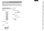
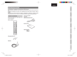
Before use, check the below accessories were
included in the package.
AM Loop Antenna
AC power cable
SETUP
User Guide
ADVANCED
CONNECTIONS
ACCESSORIES CHECK
BASIC
CONNECTIONS
INTRODUCTION
NAMES AND
FUNCTION
ENGLISH
AAA-size batteries (× 2)
This product’s packaging materials are recyclable
and can be reused. This product and the
accessories packed together are the applicable
product to the WEEE directive except batteries.
Please dispose of any materials in accordance
with your local recycling regulations.
When discarding the unit, comply with your local
rules or regulations.
Batteries should never be thrown away or
incinerated but disposed of in accordance with
your local regulations concerning chemical
wastes.
OTHERS
Microphone
TROUBLESHOOTING
ADVANCED
OPERATION
A NOTE ABOUT RECYCLING
1
SR6003_N_01_ENG 1_3.indd 1
08.7.30 3:24:32 PM
ENGLISH
NAMES AND
FUNCTION
TABLE OF CONTENTS
FEATURES
BASIC
CONNECTIONS
INTRODUCTION ....................................1
ADVANCED CONNECTIONS ..............19
TROUBLESHOOTING .........................64
ACCESSORIES CHECK ....................................................1
CONNECTING MULTI CHANNEL AUDIO COMPONENTS ..19
HDMI .................................................................................65
TABLE OF CONTENTS .........................2
CONNECTING THE USB MEDIA ....................................19
USB ...................................................................................65
CONNECTING AN EXTERNAL POWER AMPLIFIER ....20
OTHERS ...............................................67
FEATURES .............................................2
BASIC OPERATION
BEFORE USE.........................................3
SURROUND MODE .........................................................67
CONNECTION) ................................................................20
OPERATION OF REMOTE CONTROLLER ......................4
DESCRIPTION .................................................................70
CONNECTION FOR ANOTHER ZONE...........................21
TECHNICAL SPECIFICATIONS ......................................73
NAMES AND FUNCTION ......................5
CONNECTING THE REMOTE CONTROL JACKS.........22
CLEANING OF EQUIPMENT EXTERNAL SURFACES .73
FRONT PANEL ...................................................................5
CONNECTING OTHER EQUIPMENT.............................22
REPAIRS...........................................................................73
FL DISPLAY AND INDICATER ...........................................6
SETUP ..................................................23
REMOTE CONTROLLER ..................................................7
GRAPHICAL USER INTERFACE MENU SYSTEM ........23
REAR PANEL .....................................................................9
1 INPUT SETUP .............................................................25
BASIC CONNECTIONS .......................10
2 SPEAKER SETUP........................................................28
SPEAKER PLACEMENT .................................................10
ERROR MESSAGES .......................................................31
CONNECTING SPEAKERS.............................................11
3 SURROUND SETUP ...................................................34
CONNECTING AUDIO COMPONENTS..........................12
4 VIDEO SETUP .............................................................36
CONNECTING VIDEO COMPONENTS..........................13
5 PREFERENCE ............................................................37
CONNECTING HDMI COMPONENTS............................14
6 ACOUSTIC EQ ............................................................39
CONNECTING THE ANTENNA TERMINALS .................15
ADVANCED OPERATION....................41
CONNECTING THE AC POWER CABLE .......................15
AMP OPERATION ............................................................41
BASIC OPERATION ............................16
USB OPERATION ............................................................46
AMP OPERATION ............................................................16
TUNER OPERATION (PRESET MEMORY)....................50
TUNER OPERATION .......................................................16
TUNER OPERATION (RDS) ............................................52
REMOTE CONTROLLER OPERATION ..........................18
ZONE SYSTEM ................................................................53
ADVANCED
CONNECTIONS
CONNECTING FOR SPEAKER C USE (BI-AMP
SETUP
ADVANCED
OPERATION
REMOTE CONTROLLER OPERATION ..........................55
BASIC OPERATION (REMOTE CONTROLLER) ...........57
MACRO MODE.................................................................60
This unit incorporates the latest generation of digital
surround sound decoding technology such as Dolby
Digital EX, Dolby Digital, DTS ES (Discrete 6.1 and
Matrix 6.1), DTS Neo:6 (Cinema, Music), Dolby ProLogic II (Movie, Music and Game), Dolby Pro-Logic
IIx (Movie, Music and Game), Circle Surround II
(Cinema, Music and Mono).
Additionally, the unit is compatible with Dolby TrueHD
and DTS-HD (as used for Blu-ray and HD DVD discs)
as well as Dolby Digital Plus, an expanded and
improved version of Dolby Digital positioned as the
next-generation delivery format. These audio formats
can be sent with video signals via an HDMI cable to
HDMI 1.3a-compatible equipment.
In addition, Marantz has focused on the future. By
utilizing pre-out jacks, 7.1 direct inputs and a RS-232C
communication port, the unit is tomorrow’s technology,
today!
This unit can play music content that has been
recorded on USB media in the following file formats:
MP3, WMA, AAC and WAV. This means almost any
music content at hand can be played back using the
unit.
This unit uses the Graphic User Interface in the
setup menu. Setup using eye-pleasing 3D graphics
is possible using the speaker setup or acoustic
equalizer setup menu.
TROUBLESHOOTING
This unit features a fully discrete 7 channel amplifier
section capable of delivering 100 watts of highcurrent amplification, for continuously clean and
stable power into each of the 7 channels. It employs
a massive EI power transformer in combination with
oversized filter capacitors. This design configuration
is capable of a clear and powerful reproduction of
the most demanding action movie soundtracks and
full range (multichannel) music discs. Through its
ability to generate very high output voltages, the unit
can easily drive the most demanding speakers with
optimum results.
OTHERS
This unit incorporates the most advanced Digital
Signal Processing circuitry, along with a 192 kHz/24 bit
D/A converter in each of the 7 channels. Independent
power supply circuits are incorporated for the FL
display, audio and video sections for maximum
separation, clarity and dynamic range. Together with
hand-selected customized components, all elements
work in harmony to recreate the emotion, exactly as
the artist had intended.
2
SR6003_N_01_ENG 1_3.indd 2
08.7.30 3:24:33 PM
This unit supports HDCP (High-bandwidth Digital
Content Protection). HDCP is copyright protection
technology that consists of data encoding and other
device authentication. Its purpose is to protect digital
video content. Both this unit and the connected
component (such as a video player or monitor) must
support HDCP. Before connecting a component to
this unit, refer to its instruction manual.
•
•
•
•
•
•
•
•
•
•
•
•
•
•
•
•
•
EQUIPMENT MAINS WORKING SETTING
Your Marantz product has been prepared to comply
with the household power and safety requirements
that exist in your area.
SR6003 can be powered by 230V AC only.
Keep objects off the unit. Blocking the vent can result
in accident and damage.
DO NOT TOUCH HOT SPOTS DURING AND
IMMEDIATELY AFTER USE
During and immediately after use, the unit is hot
in areas other than the controls and rear panel
connection jacks. Do not touch hot spots and
especially the top panel. Contact with hot areas can
cause burns.
BASIC
CONNECTIONS
This section must be read before any connection is
made to the mains supply.
Recording and playback of any material may
require consent. For further information refer to the
following:
—
—
—
—
Copyright Act 1956
Dramatic and Musical Performers Act 1958
Performers Protection Acts 1963 and 1972
Any subsequent statutory enactments and orders
Opening and closing the front panel door
When you want to use the controls behind
the front panel door, open the door by gently
pressing on the lower part of the panel. Keep the
door closed when not using these controls.
DO NOT LOCATE IN THE FOLLOWING PLACES
To ensure long-lasting use, do not locate the unit where:
• Exposed to direct sunlight.
• Near to sources of heat such as heaters.
• Highly humid or poorly ventilated.
• Dusty.
• Subjected to mechanical vibrations.
• On wobbly, inclined or otherwise unstable surfaces
• Radiated heat is blocked such as in cramped
audio racks.
To ensure proper heat radiation, ensure the below
clearance from walls and other equipment.
Left
0.2 m (8 inchs)
or more
Above
0.2 m (8 inchs)
or more
BASIC OPERATION
COPYRIGHT
ADVANCED
CONNECTIONS
HDMI (High-Definition Multimedia Interface) is an
enhancement to the DVI (Digital Visual Interface)
standard. It adds capabilities for digitally transmitting
audio signals in addition to video signals. Where
multiple cables were previously needed for audio/
video, HDMI enables audio/video connection via a
single cable.
The HDMI input jacks of this unit support HDMI Ver.
1.3a. and the HDMI output jacks of this transmitter
support HDMI Ver. 1.3a.
•
•
•
•
•
KEEP OBJECTS OFF
BEFORE USE
SETUP
The new generation of Marantz Receivers is stylish and
completely symmetrical. On the front panel of the unit,
buttons are kept to a minimum. Source selectors and
volume controls are intuitively placed.
This unit is here to perform in your unrivaled home
entertainment setup.
•
•
•
•
•
•
•
•
•
•
•
•
•
x.v. Color
Deep Color 36bit
Dolby True HD, Dolby Digital Plus, dts HD
Dolby Digital EX, Dolby Digital, DTS ES
(Discrete 6.1, Matrix 6.1, Neo:6)
Dolby Headphone
Dolby Pro Logic II (Movie, Music, Game)
Dolby Pro Logic IIx (Movie, Music, Game)
Circle Surround II (Cinema, Music, Mono)
HDCD
Bi-amp drive
Source/Pure Direct mode
9 bands x 7 ch Graphic EQ
DSD to PCM converter
Audyssey MultEQ®
M-DAX (Marantz Dynamic Audio eXpander)
Improved Station Name Input Method, 60 Presets
Auto Adjust Function for Speaker Distance Settings
(Delay Time)
Assignable DC Trigger Output
Assignable Video Input
Auto Lipsync (Audio Delay)
7 × 100 Watts (8 Ohms), Discrete Amplifiers
Massive Energy Power Supply, Huge EI
Transformer, Large ELCO’s.
Function Rename
192 kHz/24 bit DAC for all 8 Channels
32 bit Digital Surround Processing Chipsets
Auto Input Signal Detection
Front Digital Optical Input
ZONE B Output (Digital Optical Output)
Video Off Mode
Graphical User Interface
Menu via all Video Output
(Composite, S-Video, Component Video and
HDMI)
Video Up/Down Converter
(HDMI ← Component Video ↔
S-Video ↔ Composit Video)
Two HDMI Outputs
Two Component Monitor Outputs
Analog Video Up-scaling to HDMI Output
(480/576i→480/576p→720p→1080i→1080p)
USB Audio Player (MP3, WMA, AAC, WAV)
RS-232C Terminal for Future Upgrade or System
Control
Flasher Input
Full Backlight Learning Remote Controller
Caution:
• Be careful not to pinch your fingers between the
door and the panel.
ADVANCED
OPERATION
An easy-to-use programmable, learning remote
controller allows full access to all of the operating
functions and can be used for system operation as
well.
•
•
•
•
Right
0.2 m (8 inchs)
or more
TROUBLESHOOTING
This unit is designed and engineered with extensive
feedback from custom installation experts, dealers
and consumers. It features ZONE/multisource,
assignable DC trigger, a RS-232C communication
port, Flasher input, heavy duty speaker binding posts
and an extensive array of both analog and digital
inputs / outputs. With 5 assignable digital inputs (6
total), 3 component inputs, Super Audio CD Multi
Channel (7.1 channel) direct inputs, video convert
system and a speaker-B and OSD output versatility
is taken to a stunning new level. Furthermore, the
unit can output the OSD information through the Y/C
(S-video) and composite video outputs.
NAMES AND
FUNCTION
ENGLISH
OTHERS
Rear
0.2 m (8 inchs)
or more
3
SR6003_N_01_ENG 1_3.indd 3
08.7.30 3:24:33 PM
ENGLISH
NAMES AND
FUNCTION
OPERATION OF REMOTE CONTROLLER
REMOTE CONTROL
Operate the remote controller within a distance of
approx. 5m from the infrared receptor window on the
front of the unit.
BASIC
CONNECTIONS
CAUTIONS ON BATTERIES
Before using the remote controller for the first time,
load the batteries in the remote controller. The
batteries provided are used to verify the operations
of the remote controller only.
• Use “AAA” type batteries in this remote controller.
• We recommend that you use alkaline batteries.
• If the remote controller does not operate from
close to the unit, replace the batteries with new
ones, even if less then a year has passed.
• The included battery is only for verifying operation.
Replace it with a new battery as soon as possible.
• When inserting the batteries, be careful to do so in
the proper direction, following the + and - marks in
the remote controller’s battery compartment.
• To prevent damage or battery fluid leakage:
- Do not use a new battery with an old one.
- Do not use two different types of batteries.
- Do not short-circuit, disassemble, heat or
dispose of batteries in flames.
• Remove the batteries when not planning to use
the remote controller for a long period of time.
• If the batteries should leak, carefully wipe off the
fluid from the inside of the battery compartment,
then insert new batteries.
• When disposing of used batteries, please comply
with governmental regulations or environmental
public instruction’s rules that apply in your country
or area.
SETUP
1.
Remove the battery cover.
2.
Insert the new batteries (AAA type) with correct
ª and · polarity.
3.
Close the battery cover until it clicks shut.
SR6003
rox.
App
BASIC OPERATION
ADVANCED
CONNECTIONS
LOADING BATTERIES
5m
60°
Remote controller
ADVANCED
OPERATION
Caution:
• Do not allow direct sunlight, an inverter fluorescent
light or other strong source of light to shine onto
the player’s infrared receptor window. Otherwise,
the operation of the remote controller may be
disabled.
• Bear in mind that operating the remote controller
may cause other devices operated by infrared rays
to be operated by mistake.
• The remote controller cannot be operated if the
space between the controller and the player’s
infrared receptor window is obstructed.
• Do not place any objects on top of the remote
controller.
Doing so may cause one or more buttons to be
held down which will cause the batteries to run
down.
TROUBLESHOOTING
OTHERS
4
SR6003_N_01_ENG 1_3.indd 4
08.7.30 3:24:34 PM
er t y u i o !0 !1
!2
!3
!0
T-MODE button
Press this button to select the auto stereo mode or
mono mode when the FM band is selected.
The “AUTO” indicator lights in the auto stereo mode.
(See page 17)
!1
MEMORY button
Press this button to enter the tuner preset memory
numbers or station names. (See page 50)
!2
BASIC
CONNECTIONS
FRONT PANEL
q w
BAND button
Press this button to switch between FM and AM in
the TUNER mode.
BASIC OPERATION
o
NAMES AND FUNCTION
NAMES AND
FUNCTION
ENGLISH
CLEAR button
Press this button to cancel the station-memory
setting mode or preset scan tuning. (See page 51)
Press the button to turn the power ON, and press
again to turn it OFF. If the POWER switch is in the
ON position, the power of this unit can be turned
ON/OFF by pressing the POWER button on the
remote controller.
When this unit is in the standby mode with the
POWER switch set to the ON position, pressing the
ENTER button also allows to turn the power on.
The STANDBY indicator lights up when this unit
is the standby mode (power OFF) by the remote
controller.
w
INPUT SELECTOR knob
(AUDIO/ VIDEO)
This knob is used to select the input sources. (See
page 16)
t
PURE DIRECT button and indicator
When this button is pressed once, “SOURCE
DIRECT” appears on the FL display. If pressed again,
“PURE DIRECT” appears. After 2 seconds, the FL
display indication goes out.
In the source/pure direct mode, the tone control
circuitry and bass management are bypassed.
Notes:
• The surround mode is automatically switched to
AUTO when the pure direct function is turned on.
• Additionally, speaker configurations are fixed
automatically as follows.
Front SPKR = LARGE
Center SPKR = LARGE
Surround SPKR = LARGE
Surround Back SPKR = LARGE
Sub woofer = YES
y
DISPLAY button
!4
INFRARED receiving sensor window
This window receives infrared signals for the remote
controller.
!5
ADVANCED
CONNECTIONS
POWER switch and STANDBY
indicator
!4
AUX1 INPUT jacks
These auxiliary video/audio input jacks accept the
connections of a camcorder, portable DVD, game
etc. When not using these jacks, protect by the jack
cover.
!6
Cursor (5, ∞, 2, 3) / ENTER button
Press these buttons to operate the SETUP MAIN
MENU and TUNER function.
!7
ADVANCED
OPERATION
q
!5
USB jack
Connect USB media to this USB jack.
(See page 19, 46)
TROUBLESHOOTING
!9 !8 !7 !6
VOLUME control knob
This knob is used to adjust the overall sound level.
Turning the control clockwise increases the sound
level.
SETUP
!3
Press this button to change the FL display mode.
SURROUND MODE button
Press this button to select the surround mode.
r
AUTO (Auto surround) button
Press this button to select the AUTO mode from the
surround modes. When this mode is selected, the
unit determines the surround mode corresponding to
a digital input signal automatically.
!8
u
MENU button
MIC jack
Press this button to enter the SETUP MAIN MENU.
Automatically measure speaker characteristics using
the included microphone. (See page 29)
i
!9
EXIT button
Press this button to exit from the SETUP MAIN
MENU.
HEADPHONE jack for stereo headphones
OTHERS
e
This jack may be used to listen to the unit’s output
through a pair of headphones. Be certain that the
headphones have a standard 1/4” stereo phono
plug.
5
SR6003_N_01_ENG 1_3.indd 5
08.7.30 3:24:34 PM
ENGLISH
¡7
NAMES AND
FUNCTION
FL DISPLAY AND INDICATER
a sd f
g h j k l ¡0 ¡1 ¡2 ¡3 ¡4¡5
BASIC
CONNECTIONS
WMA
WM
™0
BASIC OPERATION
a
¡6
AAC
MP3
MP
¡9
SP (speaker) ABC indicator
¡7
ex1
ex2
¡8
k
V-OFF (Video off mode) indicator
This indicator is illuminated when the speaker
system is active.
This indicator is illuminated when the Video-OFF
function is active.
s
l
SLEEP timer indicator
This indicator is illuminated when the sleep timer
function in the main-ZONE is in use.
ADVANCED
CONNECTIONS
d
MULTI (ZONE system) AB
indicator
SETUP
This indicator is illuminated when the ZONE system
is active.
g
TUNER’s indicators
ADVANCED
OPERATION
AUTO : This indicator illuminates when the
tuner’s Auto mode is in use.
TUNED : This indicator illuminates when the
tuner receives a sufficiently strong
radio signal.
ST(Stereo) : This indicator illuminates when an
FM station is being tuned into stereo
condition.
RDS : This indicator lights when an RDS
signal is being received.
TROUBLESHOOTING
h
ATT (Attenuation) indicator
This indicator is illuminated when the attenuation
function is active.
j
This indicator is illuminated when the AUTO
SURROUND mode is in use.
DISP (Display Off) indicator
This indicator is illuminated when this unit is in the
display off mode.
f
A-SURR
(Auto Surround mode) indicator
PEAK indicator
OTHERS
This indicator is a monitor for an analog audio input
signal. If the selected analog audio input signal is
greater than the capable level of internal processing,
this will illuminate. If this happens, you should press
the ATT button. (See page 8)
¡0
EQ mode indicator
This indicator is illuminated when the HT-EQ function
is active.
¡1
NIGHT mode indicator
This indicator is illuminated when this unit is in the
Night mode, which reduces the dynamic range of
digital program material at low volume levels.
¡2
M-DAX indicator
This indicator illuminates when this unit is in the MDAX mode.
¡3
HDMI indicator
This indicator is illuminated when the HDMI device is
connected to the unit.
¡4
Audyssey indicator
This indicator is illuminated when the EQ MODE is
selected to “AUDYSSEY”, “AUDYSSEY FRONT” or
“AUDYSSEY FLAT”.
¡5
DIGITAL Input Indicator
SIGNAL FORMAT indicators
2 TrueHD
This indicator is illuminated when a Dolby Digital True
HD signal is input.
2 DIGITAL
This indicator is illuminated when a Dolby Digital
signal is input.
2 DIGITAL PLUS
This indicator is illuminated when a Dolby Digital Plus
signal is input.
2 DIGITAL EX
This indicator is illuminated when a Dolby Digital EX
signal is input.
dts
This indicator is illuminated when a DTS signal is
input.
dts-HD
This indicator is illuminated when a DTS-HD signal
is input.
dts ES
This indicator is illuminated when a DTS ES signal
is input.
dts MSTR
This indicator is illuminated when a Master Audio
signal is input.
dts HIRES
This indicator is illuminated when a High Resulution
Audio signal is input.
dts 96/24
This indicator is illuminated when a DTS 96/24 signal
is input.
HDCD
This indicator is illuminated when the HDCD signal is
decoded from digital input signal.
PCM
This indicator is illuminated when the input signal is
PCM (pulse code modulation).
DSD
This indicator is illuminated when a DSD signal is
input.
AAC
This indicator lights when AAC format files on the
USB media are played back.
WMA
This indicator lights when WMA format files on the
USB media are played back.
MP3
This indicator lights when MP3 format files on the
USB media are played back.
¡8
ENCODED CHANNEL STATUS indicators
These indicators display the channels that are
encoded with a digital input signal.
If the digital input signal is Dolby Digital 5.1ch or
DTS 5.1ch, “L”, “C”, “R”, “SL”, “SR” and “LFE” will be
illuminated.
If the digital input signal is 2 channel PCM-audio, “L”
and “R” will be illuminated.
If the digital input signal is Dolby Digital 5.1ch signal
with Surround EX flag or DTS-ES, “L”, “C”, “R”, “SL”,
“S” , “SR” and “LFE” will be illuminated.
If the digital input signal is 7.1 channel PCM-audio.
“L”, “C”, “R”, “SL”, “SBL”, “SR” “SBR”, and “LFE” will
be illuminated.
If the digital input signal includes a channel other
than those above, “ex1” or “ex2” will be illuminated.
(See page 67)
Note:
When the unit is decoding Dolby TrueHD, the input
signal status displayed depends on the number of
channels of the speakers used.
If a 7.1-channel signal is supplied for a 5.1-channel
speaker system (L/C/R/SL/SR/SW), the “SBL”,
“SBR”, “S” indicator is not illuminated.
¡9
Main Information Display
This display shows messages relating to the status,
input source, surround mode, tuner, volume level or
other aspects of unit’s operation.
™0
PURE DIRECT indicator
This indicator is illuminated when this unit is in the
PURE DIRECT mode.
This indicator is illuminated when a digital input has
been selected.
¡6
ANALOG input indicator
This indicator is illuminated when an analog input
source has been selected.
6
SR6003_N_01_ENG 1_3.indd 6
08.7.30 3:24:34 PM
ENGLISH
¤5
¤4
¤3
¤2
¤1
¤0
⁄9
⁄8
n
m
,
.
⁄0
⁄1
(When Tuner mode mode is selected)
2 button
This starts playback.
PRESET +/ PRESET - buttons
Used to select a preset station up and down.
TUNE 3 /TUNE 4 buttons
Used to tune a frequency station up and down.
⁄2
EXIT / MEMO button
These button are used to turn the ZONE system on
or off.
(When AMP mode is selected)
This button is used to cancel setting in the setup
menu.
v
(When TUNER mode is selected)
This button is used to store the setting of preset
channel and others.
7.1 (7.1CH IN) button
This button is used to select the output of an external
multi channel decoder.
b
SPKR A/B button
This button is used to select the speaker system.
The speaker system is switched in the following
sequence.
A → B → A+B → off
n
MUTE button
CONTROL buttons
These buttons are used when operating PLAY, STOP,
PAUSE and other commands of a source.
∞ / § buttons
Skips forward or previous.
5 / 6 buttons
Serchs forward or backward.
⁄4
REPEAT button
This button is used to select the REPEAT mode of
a source.
RANDOM button
This button is used to select the RANDOM mode of
a source.
(When TUNER mode is selected)
⁄6
T.MODE button
This button is used to select auto stereo mode or
mono mode when the FM band is selected.
The “AUTO” indicator lights in the auto stereo mode.
These buttons are used when operating of TV and
Monitor.
This button is used to mute the audio for the
amplifier.
P.SCAN button
This button is used to start preset scan.
m
BAND button
This button is used to select a radio band.
LIGHT button
9 button
This stops playback.
⁄5
⁄3
⁄7
TV CONTROL buttons
BASS / CH +/- buttons
(When AMP mode is selected)
These buttons are used to adjust the tone control
of low frequency sound for left, right and subwoofer
speaker.
⁄2
This button is used to turn on the backlight for the
buttons.
T.DISP button
This button is used to select the display mode in
RDS.
(When TV/DSS mode are selected)
These buttons are used to change channels.
⁄3
,
This button is used to adjust the volume for the
amplifier.
PTY button
This button is used to display the programme type
information of the current station.
⁄8
.
F.DIRECT button
This button is used to select the "Frequency direct
input".
⁄4
⁄5
⁄6
⁄7
VOLUME +/- buttons
SURR (SURROUND) button
(When a mode other than DMP (USB) is selected)
This button is used to selects the surround mode.
(When DMP (USB) mode is selected)
This button is used to select the next page.
⁄0
NAMES AND
FUNCTION
; button
This pauses playback.
BASIC
CONNECTIONS
ZONE A / B buttons
(When DMP (USB) mode is selected)
P.LOCK button
This button is not used for this unit.
BASIC OPERATION
z
x
c
v
b
Z.SPKR button
(When AMP mode is selected)
This button is used to turn on and off ZONE
speaker.
c
¤7
¤6
x
1, 2, 3, 4 (CURSOR) / ENTER buttons
These buttons are used when controlling the cursor
of the unit, DVD or other AV equipment.
ADVANCED
CONNECTIONS
‹2
‹1
‹0
¤9
¤8
(When AMP mode is selected)
These buttons are used to turn the unit on or off.
⁄1
TREBLE / CAT +/- buttons
(When AMP mode is selected)
These buttons are used to adjust the tone control of
high frequency sound for left and right speaker.
⁄9
SETUP
‹3
POWER ON and OFF buttons
ADVANCED
OPERATION
The provided remote controller is a universal
remote controller. The POWER button, numeric
buttons and control buttons are used in common
across different input source components.
The input source controlled with the remote controller
changes when one of the input selector buttons is
pressed.
/
TROUBLESHOOTING
z
REMOTE CONTROLLER
CL (Clear) / T.TONE button
This button is used to erase the memory or program
of a source include the Tuner mode.
(When AMP mode is selected)
This button is used to enter the test tone menu.
INFO button
OTHERS
(When AMP mode is selected)
When this button is pressed, the current setting of AV
receiver are displayed on the connected TV monitor.
7
SR6003_N_01_ENG 1_3.indd 7
08.7.30 3:24:35 PM
ENGLISH
NAMES AND
FUNCTION
¤0
Numeric buttons
These buttons are used to switch between 0 to +10
of the source components.
If the source is set to the amplifier, these buttons are
used to perform operations.
(When AMP mode is selected)
BASIC
CONNECTIONS
1/AUTO button
This button is used to select auto surround.
2/STEREO button
This button is used to select STEREO mode.
BASIC OPERATION
3/P.DIRECT button
When this button is pressed once, SOURCE DIRECT
mode is selected.
If pressed again, PURE DIRECT mode is selected.
¤4
DISPLAY button
(When DMP mode (USB) is selected)
This button is used to select the previous page.
‹0
¤5
INPUT 3 button
This button is for forward-feeding the input source to
select a desired source.
¤6
This button is used to setup for DVD and other
device.
ADVANCED
CONNECTIONS
8/NIGHT button
Pressing this button prevents the Dolby Digital signal
from playback at a loud voice.
When this button is pressed, the “NIGHT” indicator
is illuminated.
SETUP
9/V.OFF buton
This button is used to turn off the video signal.
0/CH SEL button
This button is used to call up CH LEVEL ADJUST
and adjust speaker levels or 7.1 ch input level.
ADVANCED
OPERATION
¤1
M (MACRO) button
This button is used to program Macros. Pressing this
button switches between Normal mode and Macro
mode.
TROUBLESHOOTING
¤2
MENU button
(When AMP mode is selected)
This button is used to call up the SETUP MAIN
MENU of the unit.
¤3
TOP button
HDMI button
This button is used to select HDMI OUTPUT 1 or 2.
‹1
¤7
SETUP button
SOURCE button
These buttons are used to switch the source of your
A/V Receiver. Each time a source button is pressed,
the remote controller changes to the source which
was pressed.
This remote controller can control 12 types of
equipment. To change the A/V Receiver source,
press this button twice within two seconds. The signal
is sent when it is pressed the second time.
‹2
‹4 ‹5
‹6
‹7
SET button
This button is used to enter learn mode and preset
mode.
INPUT 4 button
This button is for backward-feeding the input source
to select a desired source.
5/M-DAX button
This button is used to select M-DAX mode.
7/LIP SYNC button
This button is used to select LIP SYNC mode.
A/D button
This button is used to switch between the analog and
digital inputs.
4/SLEEP button
This button is used for setting the sleep timer.
6/EQ button
This button is used to select Audyssey mode.
¤9
(When a mode other than DMP (USB) is selected)
This button is used to selects the display mode for the
front display of the unit.
/
‹4
LEARN indicator
This indicator is displayed when the remote controller
is in the LEARN mode.
SOURCE ON/OFF button
This button is used to turn a specific source (such as
a DVD player) on or off independently from the rest
of the system.
‹5
‹3
‹6
Infrared Transmitter and Learning
Sensor
This transmitter emits infrared light. Press the buttons
while pointing the transmitter towards the infrared
receiver window of the unit or other AV equipment.
Be sure to also point towards other remote controllers
when using the learning function.
MACRO indicator
This is displayed when a macro program is selected
by the remote controller.
Information indicator
Information about the sources and modes are shown
on the LCD.
‹7
indicator
This indicator is displayed when the remote controller
is transmitting a signal.
Notes:
• Select the AMP as the source to use this remote
controller with the unit.
• In the case of the unit, the DMP button cannot be
used.
¤8
ATT. button
When the input signal is too high and the voice
distorts even by throttling the unit VOLUME control,
turn on this function.
“ATT” is indicated when this function is activated.
The input level reduced. Attenuator is invalid for the
output signal of “REC OUT”.
Note:
This function is unavailable while the digital input is
selected.
Pressing this button during setup returns you to the
top screen of the setup main menu.
OTHERS
8
SR6003_N_01_ENG 1_3.indd 8
08.7.30 3:24:35 PM
INPUT 1
1((TV
TV))
INPUT 3
3((VCR
VCR))
COMPONENT
VIDEO
VIDEO
FM
(75
75Ω
Ω)
GND
INPUT 1
1((TV
TV))
AM
ANTENNA
INPUT 2(
2(DVD
DVD))
INPUT 3(
3(VCR
VCR))
OUTPUT 1
OUTPUT 2
S-VIDEO
AUDIO
L
SL
C
SBL
ZONE A
TV
DVD
VCR
DSS
TAPE
TV(1)
TV(
DVD((2)
DVD
CD/CDR
VCR IN
IN((3) VCR OUT
DIGITAL IN
DSS((4)
DSS
MONITOR OUT
Y
DIGITAL FLASHER IN REMOTE CONT.
REC/ZONE B
L
CB/PB
CR/PR
INPUT 2
2((DVD
DVD))
Y
CB/PB
CR/PR
OUTPUT 1
Y
CB/PB
CR/PR
OUTPUT 2
IN
4
5
1
2
MODEL NO. SR6003
R
R
(AUX 2
2))
SR
SW
7.1CH INPUT
RS-232C
SBR
OUT
IN
OUT
IN
OUT
IN
OUT
3
OUT
DC OUT
OUT
SPEAKER C
OFF ON
L
SL
C
AC IN
SBL
R
L
R
L
R
L
R
Caution:
• In order to avoid potential turn-off thumps, anything
plugged into this outlet should be powered up before
this unit is turned on.
• The capacity of this AC outlet is 150W. Do not
connect devices that consume electricity more
than the capacity of this outlet. If the total power
consumption of the connected devices exceeds the
capacity, the protection circuit shuts down the power
supply.
!5
L
o
FRONT A
R
SR
SW
SBR
FRONT B
SURROUND
CENTER
FRONT A OR B,CENTER, SURR,SURR BACK : 6-8 OHMS
FRONT A + B : 8 OHMS
SPEAKER SYSTEMS
SURROUND BACK
SPEAKER C/
ZONE SPEAKER A
!9 !8
q
!7!6 !5 !4
FM antenna terminal (75 ohms)
AM antenna and ground terminals
Connect the supplied AM loop antenna. Use the
terminals marked “AM” and “GND”. The supplied AM
loop antenna will provide good AM reception in most
areas. Position the loop antenna until you hear the
best reception.
w
HDMI INPUT/OUTPUT
The unit has 3 HDMI inputs and 2 HDMI outputs.The
input function can be selected from the GUI menu
system. (See page 26)
e
AUDIO IN/OUT (TAPE, CD/CDR, TV,
DVD, VCR, DSS)
These are the analog audio inputs and outputs. There
are 6 audio inputs (4 of which are linked to video
inputs) and 3 audio outputs (1 of which are linked to
video outputs). The audio jacks are nominally labeled
for cassette tape decks, compact disc players, DVD
players and etc.... The audio inputs and outputs
require RCA-type connectors.
r
!1 o
!2 !0
!3
Connect an external FM antenna with a coaxial
cable, or a cable network FM source.
VIDEO IN/OUT (TV, DVD, VCR, DSS)
These are the video inputs and outputs. There
are 4 video inputs and 1 video output and each
one includes both composite video and S-video
configurations. Connect VCRs, DVD players, and
other video components to the video inputs.
The video output channel can be used to be connected
to video tape recorders for making recordings.
50/60Hz
SWITCHED
0.65A 150W
PRE OUT
t
!0
i
u
MONITOR OUT
This is a monitor output and each one includes both
composite video and S-video configurations. When
connecting two video monitors or televisions, be
aware that the OSD interface can be used with both
MONITOR OUT connections.
y
COMPONENT VIDEO INPUT/
OUTPUT
If your DVD player or other device has component
video connectors, be sure to connect them to these
component video connectors on the unit. This unit
has two component video input connectors to obtain
the color information (Y, CB, CR) directly from the
recorded DVD signal or other video component and
one component video output connector to output it
directly into the matrix decoder of the display device.
By sending the pure DVD component video signal
directly, the DVD signal forgoes the extra processing
that normally would degrade the image. The result is
vastly increased image quality, with incredibly life like
colors and crisp detail.
When the video convert function is enabled, video and
S-video images can be output to the COMPONENT
VIDEO OUTPUT jacks.
u
REMOTE CONT. IN/OUT terminals
Connect to a Marantz component equipped with
remote control (RC-5) terminals.
AC OUTLET
230V
AC INLET
Plug the supplied power cable into this AC INLET
and then into the power outlet on the wall.
This unit can be powered by 230V AC only.
FLASHER IN
(Flasher input terminal)
These terminals are to control the unit from each
ZONE. Connect the control signal from a Keypad,
etc.
!1
DC TRIGGER output terminal
Connect a device that needs to be triggered by DC
under certain conditions (screen, power strip, etc…)
Use the system GUI setup menu to determine the
conditions by which these jack will be active.
Note:
This output voltage is for (status) control only, It is not
sufficient for drive capability.
!2
DIGITAL INPUT
(DIGITAL IN 1-5) / OUTPUT (optical)
These are the digital audio inputs and output.
The unit has 2 digital inputs with coaxial jacks, 3 with
optical jacks.
The inputs accept digital audio signals from a CD,
DVD, or other digital source component.
For digital output, this is 1 optical output.
The digital outputs can be connected to MD recorders,
CD recorders, or other similar components.
In addition, this digital output can be used as ZONE
B output.
!3
SPEAKER C SELECTOR SWITCH
The terminals can be used to connect a third set of
speakers by setting the SPEAKER C selector switch
to ON. For connection and use, see page 20.
!6
Preamp Outputs
(L, R, SL, SR, SBL, SBR, C)
BASIC
CONNECTIONS
y
Jacks for L(front left), R (front right), C (Center), SL
(surround left), SR (surround right), SBL (surround
back left) and SBR (surround back right).
Use these jacks for connection to external power
amplifiers.
!7
Subwoofer Output
Connect this jack to the line level input of a powered
subwoofer. If an external subwoofer amplifier is used,
connect this jack to the subwoofer amplifier input.
If you are using two subwoofers, either powered or
with a 2 channel subwoofer amplifier, connect a “Y”
connector to the subwoofer output jack and run one
cable from it to each subwoofer amplifier.
!8
BASIC OPERATION
t
ADVANCED
CONNECTIONS
r
RS-232C
The RS-232C port is to be used in conjunction with
an external controller to control the operation of the
unit by using an external device.
!9
SETUP
e
ZONE A Outputs
These are the audio output jacks for the ZONE A.
Connect these jacks to optional audio power
amplifiers to listen the source selected by the ZONE
system in a remote room.
7.1 CHANNEL or AUX2 INPUT
By connecting a DVD Audio player, Super Audio CD
multichannel player, or other components that has a
multichannel port, you can playback the audio with
5.1 channel or 7.1 channel outputs.
TROUBLESHOOTING
w
!4
Speaker outputs terminals
Seven terminals are provided for the front left,
front right, front center, surround left, surround
right, surround back left and surround back right
speakers.
OTHERS
q
AC OUTLET
Connect the AC power cable of component such as
a DVD or CD player to this outlet.
This outlet provides power only when this unit is
turned on.
ADVANCED
OPERATION
i
REAR PANEL
NAMES AND
FUNCTION
ENGLISH
Note:
You can use surround back speaker terminals as
ZONE SPEAKER A terminals, when you use no
surround back speaker.
9
SR6003_N_01_ENG 1_3.indd 9
08.7.30 3:24:36 PM
ENGLISH
NAMES AND
FUNCTION
BASIC CONNECTIONS
Front left and right speakers
We recommend to set the front L and R speakers
with 45-60 degrees from the listening position.
SPEAKER PLACEMENT
Center speaker
Align the front line of the center speaker with the front
L/R speakers. Or place the center speaker a little
backward from the line.
BASIC
CONNECTIONS
BASIC OPERATION
ADVANCED
CONNECTIONS
SETUP
The ideal surround speaker system for this unit is 7speaker systems, using front left and right speakers,
a center speaker, surround left and right speakers,
a surround back left and right speakers, and a
subwoofer.
For best results we recommend that all front speakers
be of the same type, with identical or similar driver
units. This will deliver smooth pans across the front
sound stage as the action moves from side to side.
Your center channel speaker is very important as
over 80 % of the dialog from a typical motion picture
emanates from the center channel.
It should possess similar sonic characteristics to the
main speakers. Surround channel speakers need not
be identical to the front channel speakers, but they
should be of high quality.
The surround center speaker is useful for playback
of Dolby Digital Surround EX or DTS-ES. One of
the benefits of both Dolby Digital and DTS is that
surround channels are discrete full range, while they
were frequency limited in earlier “Pro Logic” type
systems.
Bass effects are an important part of home theater.
For optimal enjoyment a subwoofer should be used
as it is optimized for low frequency reproduction. If you
have full range front speakers, however, they may be
used in place of a subwoofer with proper setting of the
switches in the menu system.
Subwoofer
Surround Right
Front Right
Surround Back Right
Front Center
Surround back left and right speakers
Surround back speakers are required when a full 7.1channel system is installed.
Speakers should be placed on a rear wall, behind the
listening position.
The center of the speaker should face into the room.
Front Left
Surround Left
Surround left and right speakers
When this unit is used in surround operation, the
preferred location for surround speakers is on the
side walls of the room, at or slightly behind the
listening position.
The center of the speaker should face into the room.
Surround Back Left
HEIGHT OF THE SPEAKER UNITS
Front left and right speakers, and a center speaker
Align the tweeters and mid-range drivers on the
three front speakers at the same height, as best as
possible.
Surround left and right speakers, and surround
back speaker
Place the surround left, right and surround back
speakers higher than your ears by about 70cm–1m.
Also place the speakers at the same height, as best
as possible.
70cm
1m
Subwoofer
We recommend using a sub-woofer to have maximum
bass effect. As the subwoofer only handle low frequency.
You can place it any where in the room.
Note:
• Use magnetically-shielded speakers for front left,
right and the center speakers when the speakers are
installed near the TV.
ADVANCED
OPERATION
TROUBLESHOOTING
OTHERS
10
SR6003_N_01_ENG 1_3.indd 10
08.7.30 3:24:36 PM
Left
Right
INPUT 1
1((TV
TV))
INPUT 3(
3(VCR
VCR))
GND
AM
INPUT 3(
3(VCR
VCR))
OUTPUT 1
OUTPUT 2
S-VIDEO
AUDIO
L
SL
C
SBL
ZONE A
TV
DVD
VCR
DSS
TAPE
2.
Twist the bared wire ends tight, to prevent short
circuits.
3.
4.
Loosen the knob by turning it counterclockwise.
5.
Tighten the knob by turning it clockwise to
secure the wire.
Insert the bare part of the wire into the hole in
side of each terminal.
1.
ANTENNA
INPUT 2(
2(DVD
DVD))
Strip away approx. 10 mm (3/8 inch) of wire
insulation.
COMPONENT
VIDEO
VIDEO
FM
(75
75Ω
Ω)
INPUT 1(
1(TV
TV))
1.
Surround BACK
FRONT B
Left
Right
TV(1)
TV(
DVD(2)
DVD(
CD/CDR
VCR IN
IN((3) VCR OUT
DIGITAL IN
DSS(4)
DSS(
MONITOR OUT
Y
DIGITAL FLASHER IN REMOTE CONT.
REC/ZONE B
L
CB/PB
CR/PR
INPUT 2(
2(DVD
DVD))
Y
CB/PB
CR/PR
OUTPUT 1
Y
2.
CB/PB
CR/PR
OUTPUT 2
IN
4
5
1
2
MODEL NO. SR6003
R
R
(AUX 2)
2)
SR
SW
7.1CH INPUT
RS-232C
SBR
OUT
IN
OUT
IN
OUT
IN
OUT
3
OUT
DC OUT
10 mm
(3/8 inch)
OUT
SPEAKER C
OFF ON
L
SL
C
AC IN
SBL
R
L
FRONT A
R
SR
SW
SBR
R
L
FRONT B
R
L
SURROUND
FRONT A OR B,CENTER, SURR,SURR BACK : 6-8 OHMS
FRONT A + B : 8 OHMS
SPEAKER SYSTEMS
R
CENTER
BASIC
CONNECTIONS
FRONT A
Left
Right
L
SURROUND BACK
SPEAKER C/
ZONE SPEAKER A
AC OUTLET
230V
50/60Hz
SWITCHED
0.65A 150W
PRE OUT
3.
4.
5.
• Do not touch the speaker terminals when the
power is on. It may cause you to receive an electric
shocks.
• Do not connect more than one speaker cable to one
speaker terminal. Doing so may damage this unit.
Note:
• Be sure to connect the positive and negative cables for
the speaker properly. If they are miss-connected, the
signal phase will be reversed and the signal quality will
be corrupted.
CONNECTING A SUBWOOFER
Center
OTHERS
TROUBLESHOOTING
ADVANCED
OPERATION
Right
Left
Surround
SETUP
Use the PRE OUT SUBWOOFER jack to connect a
powered subwoofer (power amplifier built in ).
BASIC OPERATION
Powered
subwoofer
Caution:
• Be sure to use speakers with the specified impedance as
shown on the rear panel of this unit.
• To prevent damage to circuitry, do not let the bare
speaker wires touch each other and do not let them
touch any metal part of this unit.
ADVANCED
CONNECTIONS
CONNECTING SPEAKER WIRE
CONNECTING SPEAKERS
NAMES AND
FUNCTION
ENGLISH
11
SR6003_N_01_ENG 1_3.indd 11
08.7.30 3:24:36 PM
ENGLISH
NAMES AND
FUNCTION
CONNECTING AUDIO COMPONENTS
Tape Deck
CD recorder
Caution:
• Do not connect this unit and other components
to mains power until all connections between
components have been completed.
OUT IN
BASIC
CONNECTIONS
OUT IN
L
L
R
R
L R
DIGITAL
INPUT
DIGITAL
OUTPUT
R L
L
L
R
R
L R
L R
L R
L R
BASIC OPERATION
INPUT 1
1((TV
TV))
VIDEO
FM
(75
75Ω
Ω)
GND
INPUT 1(
1(TV
TV))
AM
ANTENNA
INPUT 2(
2(DVD
DVD))
INPUT 3(
3(VCR
VCR))
OUTPUT 1
OUTPUT 2
S-VIDEO
AUDIO
L
SL
C
SBL
ZONE A
TV
DVD
VCR
TAPE
DSS
TV((1)
TV
DVD(2)
DVD(
CD/CDR
VCR IN
IN((3) VCR OUT
DIGITAL IN
DSS(4)
DSS(
MONITOR OUT
Y
DIGITAL FLASHER IN REMOTE CONT.
REC/ZONE B
L
CB/PB
CR/PR
INPUT 2
2((DVD
DVD))
IN
4
5
1
2
MODEL NO
NO. SR6003
R
R
(AUX 2)
2)
SR
SW
7.1CH INPUT
RS-232C
SBR
OUT
IN
IN
OUT
OUT
IN
OUT
3
OUT
DC OUT
OUT
SPEAKER C
OFF ON
ADVANCED
CONNECTIONS
L
SL
C
AC IN
SBL
R
L
FRONT A
R
SR
SW
SBR
R
L
FRONT B
R
L
SURROUND
R
CENTER
FRONT A OR B,CENTER, SURR,SURR BACK : 6-8 OHMS
FRONT A + B : 8 OHMS
SPEAKER SYSTEMS
L
SURROUND BACK
SPEAKER C/
ZONE SPEAKER A
AC OUTLET
230V
50/60Hz
SWITCHED
0.65A 150W
PRE OUT
R L
R L
The output audio signal from the TAPE OUT jack and
the CD/CD RECORDER OUT jack is the same signal
which is currently selected.
Notes:
• Insert all plugs and connectors securely. Incomplete
connections may make noise.
• Be sure to connect the left and right channels
properly.
Red connectors are for the R (right) channel, and
white connectors are for the L (left) channel.
• Be sure to connect input and output properly.
• Refer to the instructions for each component that is
connected to this unit.
• Do not bind audio/video connection cables with
power cables and speaker cables this will result in
generating a hum or other noise.
CONNECTING DIGITAL AUDIO COMPONENTS
• There are 5 digital inputs, 2 coaxial jacks and
3 optical jacks, on the rear panel. You can use
these jacks to input PCM, Dolby Digital and DTS
bitstream signals from a CD, DVD, or other digital
source components.
• There is one optical output jack on the rear panel.
This jack can be connected to a CD recorder or
a MD recorder input.When you use this jack as
ZONE B, you cannot use it as recording output.
(See page 9, 38)
• Refer to the instructions for each component. To
setup the digital audio format of DVD player, or
other digital source’s connected to digital input
jacks.
• Use fiber optical cables (optical) for DIG-1,2,3
input jacks and REC/ZONE B output jack. Use 75
ohms coaxial cables (for digital audio or video) for
DIG-4, 5 input jacks.
• You can designate the input for each digital input/
output jacks according to your component. (See
page 26)
SETUP
Notes:
• The digital signal jacks on this unit conform to
the EIA standard. If you use a cable that does not
conform to this standard, this unit may not function
properly.
• Each type of audio jack works independently.
Signals input through the digital and analog jacks are
output through the corresponding digital and analog
jacks, respectively.
L R
ADVANCED
OPERATION
Analog Audio
Digital Audio (coaxial)
TROUBLESHOOTING
Digital Audio (optical)
OTHERS
12
SR6003_N_01_ENG 1_3.indd 12
08.7.30 3:24:37 PM
ENGLISH
DVD player
COMPONENT
VIDEO IN
COMPONENT
VIDEO OUT
Y
Y
CB / PB CR / PR
S-VIDEO
IN
CB / PB CR / PR
DIGITAL
OUT
VIDEO
OUT
AUDIO
OUT
S-VIDEO
OUT
L R
L R
L
R L
INPUT 1
1((TV
TV))
INPUT 3(
3(VCR
VCR))
INPUT 1(
1(TV
TV))
COMPONENT
VIDEO
VIDEO
GND
INPUT 1(TV)
OUTPUT 2
AM
INPUT 2(
2(DVD
DVD))
INPUT 3(
3(VCR
VCR))
OUTPUT 1
OUTPUT 2
ZONE A
TV
VCR
DVD
DSS
TAPE
DSS(4)
DSS(
VCR IN
IN((3) VCR OUT
DVD(2)
DVD(
TV(1)
TV(
CD/CDR
DIGITAL IN
MONITOR OUT
Y
DIGITAL FLASHER IN REMOTE CONT.
REC/ZONE B
CB/PB
CR/PR
INPUT 2
2((DVD
DVD))
Y
CB/PB
CR/PR
OUTPUT 1
4
5
1
2
Y
AUDIO
CB/PB
CR/PR
OUTPUT 2
L
SL
C
SBL
ZONE A
TV
DVD
DSS
VCR
TAPE
TV(1)
TV(
DVD(2)
DVD(
CD/CDR
VCR IN
IN((3) VCR OUT
DIGITAL IN
DSS(4)
DSS(
MONITOR OUT
Y
DIGITAL FLASHER IN REMOTE CONT.
REC/ZONE B
L
IN
CB/PB
CR/PR
INPUT 2(
2(DVD
DVD))
4
5
IN
OUT
OUT
IN
OUT
IN
OUT
3
OUT
DC OUT
R
(AUX 2)
OUT
SR
SW
7.1CH INPUT
NPUT
RS-232C
SPEAKER
AKER C
SBR
OUT
IN
OUT
IN
OUT
IN
OUT
1
2
3
OUT
DC OUT
OUT
SPEAKER C
OFF ON
ON
AC IN
SBL
R
L
FRONT A
SBR
R
L
FRONT B
R
L
SURROUND
FRONT A OR B,CENTER, SURR,SURR BACK : 6-8 OHMS
FRONT A + B : 8 OHMS
SPEAKER SYSTEMS
R
CENTER
L
SL
C
AC IN
SBL
R
L
SURROUND BACK
SPEAKER C/
ZONE SPEAKER A
L
FRONT A
AC OUTLET
230V
50/60Hz
SWITCHED
0.65A 150W
R
SR
SW
SBR
R
L
R
FRONT B
L
SURROUND
FRONT A OR B,CENTER, SURR,SURR BACK : 6-8 OHMS
FRONT A + B : 8 OHMS
SPEAKER SYSTEMS
R
CENTER
L
SURROUND BACK
SPEAKER C/
ZONE SPEAKER A
AC OUTLET
230V
50/60Hz
SWITCHED
0.65A 150W
PRE OUT
R L
Video
L R
S-Video
R L
L R
AUDIO
OUT
L R
AUDIO
OUT
AUDIO
IN
L R
L R
VIDEO
OUT
VIDEO
IN
Digital Audio
(coaxial)
L R
VIDEO
OUT IN
Digital Audio
(optical)
S-VIDEO
OUT IN
TV
VCR
S-VIDEO
IN
L R
Analog Audio
L R
CB/PB
CR/PR
OUTPUT 1
MODEL NO. SR6003
R
SBR
Y
IN
MODEL NO. SR6003
Y
CB/PB
CR/PR
OUTPUT 2
Notes:
• Be sure to connect the left and right audio channels
properly.
Red connectors are for the R (right) channel, and
white connectors are for the L (left) channel.
• Be sure to connect the inputs and outputs of the
video signals properly.
• If you connect the S-VIDEO or component signal to
the S-VIDEO or component jack on this unit, it is not
necessary to connect the conventional video signal to
the VIDEO (composite) jack. If you use both video
inputs, this unit gives priority to the S-VIDEO signal.
• Each type of video jack works independently.
Signals input to the VIDEO (composite) and SVIDEO jacks or component are output to the
corresponding VIDEO (composite) and S-VIDEO
or component jacks, respectively.
• This unit has the “TV-AUTO ON/OFF” function to
turn the TV ON or OFF automatically, by sensing the
incoming video signal from the VIDEO jacks.
• You may need to setup the digital audio output
format of your DVD player, or other digital source
components. Refer to the instructions of the each
component connected to the digital input jacks.
• The COMPONENT OUTPUT 1 and 2 terminals of
this unit can output the same video signal. (See page
36)
ADVANCED
CONNECTIONS
S-VIDEO
S-VIDEO
AUDIO
SBL
COMPONENT
VIDEO
ANTENNA
SETUP
OUTPUT 1
INPUT 3(VCR)
VIDEO
FM
(75Ω)
ADVANCED
OPERATION
INPUT 3(
3(VCR
VCR))
COMPONENT jack
Make component video connections to a TV or
monitor with component inputs to produce higher
quality video images. Use a component video cable
or 3 video cords to connect the component video out
jacks on the unit to the monitor.
R L
ANTENNA
INPUT 2
2((DVD
DVD))
R
TROUBLESHOOTING
S-VIDEO
OUT
S-VIDEO jack
The video signal is separated into luminance (Y) and
color (C) signals for the S-VIDEO jack. The S-VIDEO
signals enables high-quality color reproduction. If
your video component has an S-VIDEO output, we
recommend to use it. Connect the S-VIDEO output
jack on your video component to the S-VIDEO input
jack on this unit.
OTHERS
VIDEO
OUT
DIGITAL AUDIO
OUT
OUT
L R
VIDEO jack
The video signal for the VIDEO jacks is the
conventional composite video signal.
Satellite Tuner
BASIC OPERATION
There are 3 types of video jacks on the rear panel.
VIDEO
PROJECTOR
BASIC
CONNECTIONS
NAMES AND
FUNCTION
VIDEO, S-VIDEO, COMPONENT JACKS
CONNECTING VIDEO COMPONENTS
13
SR6003_N_01_ENG 1_3.indd 13
08.7.30 3:24:37 PM
ENGLISH
NAMES AND
FUNCTION
HDMI JACKS
CONNECTING HDMI COMPONENTS
DVD player
HDMI OUTPUT
BASIC
CONNECTIONS
This unit has three HDMI inputs and two HDMI
outputs. It can send digital video and audio signals
from DVDs and other sources directly to a display.
It minimizes signal degradation caused by analog
conversion so that high quality images can be
enjoyed.
This unit is also capable of converting analog video
signals (Composite Video, S-Video, Component
Video) for HDMI output.
Select an input source from the GUI menu system. (See
page 26)
VIDEO PROJECTOR
HDMI INPUT
BASIC OPERATION
INPUT 1(
1(TV
TV))
INPUT 3(
3(VCR
VCR))
COMPONENT
VIDEO
VIDEO
FM
(75
75Ω
Ω)
GND
INPUT 1(
1(TV
TV))
AM
ANTENNA
INPUT 2
2((DVD
DVD))
INPUT 3
3((VCR
VCR))
OUTPUT 1
OUTPUT 2
S-VIDEO
AUDIO
L
SL
C
SBL
ZONE A
TV
DVD
VCR
DSS
TAPE
TV(1)
TV(
DVD(2)
DVD(
CD/CDR
VCR IN
IN((3) VCR OUT
DIGITAL IN
DSS(4)
DSS(
MONITOR OUT
Y
DIGITAL FLASHER IN REMOTE CONT.
REC/ZONE B
L
CB/PB
CR/PR
INPUT 2
2((DVD
DVD))
Y
CB/PB
CR/PR
OUTPUT 1
IN
4
5
1
2
MODEL NO. SR6003
R
R
(AUX 2)
2)
SR
SW
7.1CH INPUT
ADVANCED
CONNECTIONS
RS-232C
SBR
OUT
IN
OUT
IN
OUT
IN
OUT
3
OUT
DC OUT
OUT
SPEAKER C
OFF ON
L
SL
C
AC IN
SBL
R
L
FRONT A
R
SR
SW
SBR
R
L
FRONT B
R
SURROUND
FRONT A OR B,CENTER, SURR,SURR BACK : 6-8 OHMS
FRONT A + B : 8 OHMS
SPEAKER SYSTEMS
PRE OUT
L
R
CENTER
L
SURROUND BACK
SPEAKER C/
ZONE SPEAKER A
AC OUTLET
230V
50/60Hz
SWITCHED
0.65A 150W
Y
CB/PB
CR/PR
OUTPUT 2
Notes:
• When the HDMI output is connected to a display
monitor that does not support HDCP*, signals are
not output. To view images in HDMI, it is necessary
to connect to a display that supports HDCP.
• There may be no image output if connected to a
TV or display that is not compatible with the above
format.
• Refer to the instruction manual of the TV or display
to be connected to the unit for detailed information
regarding the HDMI terminal.
* HDCP: High-bandwidth Digital Content Protection
CONNECTING HDMI COMPONENTS
SETUP
SATELLITE TUNER
HDMI OUTPUT
An HDMI cable (sold separately) is used to connect the
HDMI jack on the unit with the HDMI jack on the DVD
player, TV, projector or other component. To transmit
multichannel audio via HDMI, the connected player
must support multichannel audio transmission through
its HDMI jack.
• Some source devices such as DVD players or set
top box do not support HDMI repeater operations
like those of the unit. In such case, pictures are not
properly projected on monitors such as TVs and
projectors.
• When multiple components are connected to this
unit, turn power to unused components off to
prevent interference between them.
• Disconnecting or connecting cables with the power
on can damage the equipment. Turn the power off
before disconnecting or connecting cables.
• If the DVD player that does not support HDMI 1.1
or later is connected to the unit, multi channel PCM
playback is not possible even with DVD-Audio
disks.
• If the Super Audio CD player that does not support
HDMI 1.2 or later is connected to the unit, DSD*
playback is not possible even with Super Audio
CD.
(*DSD: Direct Stream Digital)
• The following functions are not available when the
unit is connected to equipment that does not support
HDMI 1.3a.
• Deep Color
• x.v. Color
• Bitstream audio signal decoding, as for Dolby
Digital Plus, Dolby TrueHD, DTS-HD, and so on
For details, refer to the user’s manuals of connected
equipment.
• Multi channel PCM signals and audio signals of 64
kHz or higher that are input from the HDMI jack are
not output from the DIGITAL OUT jack.
• Depending on the quiality of the cable used, the
HDMI signal may be affected by noise.
ADVANCED
OPERATION
TROUBLESHOOTING
Notes:
• Some HDMI components can be controlled over
the HDMI cable, but this unit cannot control other
components this way.
• When connected to a monitor (i.e., TV, projector,
etc.) that does not support HDCP, video and audio
are not output.
OTHERS
14
SR6003_N_01_ENG 1_3.indd 14
08.7.30 3:24:37 PM
INPUT 3(
3(VCR
VCR))
COMPONENT
VIDEO
VIDEO
FM
(75
75Ω
Ω)
GND
INPUT 1
1((TV
TV))
AM
ANTENNA
INPUT 2
2((DVD
DVD))
INPUT 3(
3(VCR
VCR))
OUTPUT 1
OUTPUT 2
S-VIDEO
AUDIO
L
SL
C
SBL
ZONE A
TV
DVD
VCR
DSS
TAPE
TV(1)
TV(
DVD(2)
DVD(
CD/CDR
VCR IN
IN((3) VCR OUT
DIGITAL IN
DSS(4)
DSS(
MONITOR OUT
Y
DIGITAL FLASHER IN REMOTE CONT.
REC/ZONE B
L
CB/PB
CR/PR
INPUT 2
2((DVD
DVD))
Y
CB/PB
CR/PR
OUTPUT 1
IN
4
5
1
2
MODEL NO. SR6003
R
R
(AUX 2)
2)
SR
SW
7.1CH INPUT
RS-232C
SBR
OUT
IN
OUT
IN
OUT
IN
OUT
3
OUT
DC OUT
OUT
SPEAKER C
OFF ON
L
SL
C
SBL
FM (75) R
GND
L
FRONT A
R
SR
SW
SBR
AM
R
L
AC IN
ANTENNA
ANT
R
L
FRONT B
SURROUND
FRONT A OR B,CENTER, SURR,SURR BACK : 6-8 OHMS
FRONT A + B : 8 OHMS
SPEAKER SYSTEMS
PRE OUT
R
CENTER
L
SURROUND BACK
SPEAKER C/
ZONE SPEAKER A
AC OUTLET
230V
50/60Hz
SWITCHED
0.65A 150W
2.
Release the vinyl tie and take out the connection
line.
Bend the base part in the reverse direction.
Y
CB/PB
CR/PR
OUTPUT 2
1.
Press and hold down the lever of the AM antenna
terminal.
2.
3.
Insert the bare wire into the antenna terminal.
Release the lever.
Note:
• Connect the shielded grounding wire (black) to the
AM antenna GND terminal.
ASSEMBLING THE AM LOOP ANTENNA
1.
4.
Place the antenna on stable surface.
CONNECTING THE FM OUTDOOR ANTENNA
Notes:
• Keep the antenna away from noise sources (neon
signs, busy roads, etc.).
• Do not put the antenna close to power lines. Keep it
well away from power lines, transformers, etc.
• To avoid the risk of lightning and electrical shock,
grounding is necessary.
CONNECTING THE AM OUTDOOR ANTENNA
The outdoor antenna will be more effective if it is
stretched horizontally above a window or outside.
Insert the hook at the bottom of the loop part
into the slot at the base part.
Notes:
• Do not remove the AM loop antenna.
• To avoid the risk of lightning and electrical shock,
grounding is necessary.
INPUT 3
3((VCR
VCR))
COMPONENT
VIDEO
TV(1
1)
DVD(2)
DVD(
VCR IN(
IN(3) VCR OUT
DIGITAL IN
DSS(4)
DSS(
MONITOR OUT
Y
DIGITAL FLASHER IN REMOTE CONT.
REC/ZONE B
CB/PB
CR/PR
INPUT 2(
2(DVD
DVD))
Y
CB/PB
CR/PR
OUTPUT 1
Y
CB/PB
CR/PR
OUTPUT 2
IN
4
5
1
2
MODEL NO. SR6003
3
OUT
DC OUT
OUT
AC IN
R
L
SURROUND BACK
SPEAKER C/
ZONE SPEAKER A
AC OUTLET
230V
AC IN
50/60Hz
SWITCHED
0.65A 150W
2.
Plug the power cable into an AC outlet.
OTHERS
3.
INPUT 1(
1(TV
TV))
BASIC
CONNECTIONS
Connecting the supplied AM loop antenna
The supplied AM loop antenna is for indoor use
only.
Set it in the direction and position it to where you
receive the clearest sound. Put it as far away as
possible from the unit, televisions, speaker cables,
and power cords.
If you experience poor reception quality, an outdoor
antenna may improve the quality.
Plug the supplied AC power cable to the AC IN
socket on the rear panel of the unit.
BASIC OPERATION
INPUT 1
1((TV
TV))
1.
ADVANCED
CONNECTIONS
Connecting the supplied FM antenna
The supplied FM antenna is for indoor use only.
During use, extend the antenna and move it in various
directions until the clearest signal is received.
Fix it with push pins or similar implements in
the position that will cause the least amount of
distortion.
If you experience poor reception quality, an outdoor
antenna may improve the quality.
AM External
Antenna
SETUP
AM Loop
Antenna
FM External
Antenna
ADVANCED
OPERATION
FM Antenna
CONNECTING THE AC POWER CABLE
TROUBLESHOOTING
CONNECTING THE SUPPLIED ANTENNAS
CONNECTING THE ANTENNA TERMINALS
NAMES AND
FUNCTION
ENGLISH
15
SR6003_N_01_ENG 1_3.indd 15
08.7.30 3:24:38 PM
ENGLISH
NAMES AND
FUNCTION
BASIC OPERATION
AMP OPERATION
TURNING ON THE UNIT
BASIC
CONNECTIONS
BASIC OPERATION
1.
2.
ADVANCED
CONNECTIONS
3.
Connect the AC power cable to the wall outlet.
• As the input source is changed, the new input
name will appear momentarily an OSD information
on the video display. The input name will also
appear in the display, on the front-panel.
• If you use the FUNCTION RENAME feature (see
page 27) , the renamed name appears on the
display.
• As the input is changed, this unit will automatically
switch to the digital input, surround mode,
attenuation, and night mode status which were
entered during the configuration process for that
source.
• When a video source is selected, the selected
video signal is output from the MONITOR OUT
terminal.
ADJUSTING THE MAIN VOLUME
Turn the power of the equipment connected to
this unit on.
Press the POWER ON/OFF button on the main
unit. The power of the main unit switches on/off
each time this button is pressed.
Pressing POWER OFF or SOURCE ON/OFF
after pressing the AMP button on the remote
controller causes the STANDBY indicator on
the main unit to light, and the main unit to go
into standby mode.
SETUP
To turn the power on while in standby mode,
press the ENTER button on the main unit or
the AMP button on the remote controller, then
press POWER ON or SOURCE ON/OFF.
ADVANCED
OPERATION
SELECTING AN INPUT SOURCE
Before you can listen to any input media, you must
first select the input source on the unit.
Example : DVD
TROUBLESHOOTING
OTHERS
To select DVD, turn the INPUT SELECTOR knob
on the front panel or press the DVD button on the
remote controller two times in a row. After you have
selected DVD, simply turn on the DVD player and
play the DVD.
Adjust the volume to a comfortable level using
the VOLUME control knob on the front panel or
VOLUME + / – buttons on the remote controller.
To increase the volume, turn the VOLUME knob
clockwise or press VOLUME + button on the
remote controller, to decrease the volume, turn
counterclockwise or press VOLUME – button on the
remote controller.
Notes:
• The volume can be adjusted within the range of – ∞
and –71 to 18 dB, in steps of 1 dB.
• However, when the channel level is set as described on
page 34, if the volume for any channel is set at +1 dB
or greater, the volume cannot be adjusted up to 18 dB.
(In this case the maximum volume adjustment range
is “18 dB - Maximum value of channel level)
ADJUSTING THE TONE (BASS & TREBLE)
CONTROL
TUNER OPERATION
To operate the unit from the remote controller, press
the TUNE button on the remote controller so that the
tuner mode is engaged.
LISTENING TO THE TUNER
During a listening session you may wish to adjust the
Bass and Treble Control to suit your listening tastes
or room acoustics.
(Using the remote controller)
To adjust the tone, press the AMP button.
To adjust the bass effect, press BASS + or BASS
– button.
To adjust the treble effect, TREBLE + or TREBLE
– button.
Notes:
• The tone control function is unavailable for the
Source Direct, Pure Direct, Headphone, Dolby
Virtual Speaker mode, and 176.4/192kHz PCM.
• The Tone control function is not available when MDAX is being used.
• The tone control function is not available when
ACOUSTIC EQ is being used.
• Additionally, tone control is not available during
Dolby TrueHD, Dolby Digital Plus, or DTS-HD
playback.
Frequency scan step for AM is selectable.
Default setup is 9 kHz step, if your country’s standard
is 10 kHz step, Press BAND button on the front panel
or BAND button on the remote controller more than 5
seconds. Scan step will change.
Note:
• Preset memory for the tuner will clear by changing
this setup.
AUTO TUNING
1.
3. 2.
1.
TEMPORARILY TURNING OFF THE SOUND
3.
2.
To temporarily silence all speaker outputs such as
when interrupted by a phone call, press the MUTE
button on the remote controller.
This will interrupt the output to all speakers and the
head-phone jack, but it will not affect any recording or
dubbing that may be in progress.
When the system is muted, the display will show
“MUTE” .
Press the MUTE button again to return to normal
operation.
(Using the unit)
1.
Turn the INPUT SELECTOR knob to select
“TUNER”.
2.
Press the BAND button to select either FM or
AM.
3.
Press the 3 or 4 cursor buttons on the front
Panel for more than 1 second to start the auto
tuning function.
4.
Automatic searching begins then stops when a
station is tuned in.
16
SR6003_N_01_ENG 1_3.indd 16
08.7.30 3:24:38 PM
ENGLISH
Automatic searching begins then stops when a
station is tuned in.
NAMES AND
FUNCTION
4.
1.
2.
3
If tuning does not stop at the desired station, use to
the “Manual tuning” operation.
4.
1.
3.
2.
(Using the unit)
1.
Turn the INPUT SELECTOR knob to select
“TUNER”.
2.
Press the BAND button to select either FM or
AM.
3.
Press the 3 or 4 cursor buttons on the front
Panel to select the desired station.
(Using the remote controller)
To select tuner, press the TUNE button twice
within two seconds on the remote controller.
2.
Press the BAND button to select either FM or
AM.
3.
Press the TUNE 3 or 4 button to tune in the
deseired station.
To select tuner, Press the TUNE button twice
within two seconds on the remote controller.
2.
Press the BAND button to select either FM or
AM.
3.
Press the F.DIRECT on the remote controller,
display will show “FREQ----”.
4.
lnput your desired station’s, frequency with the
ten numbered keypad on the remote controller.
5.
The desired station will automatically be tuned.
OTHERS
1.
1.
When in the auto stereo mode, “AUTO” indicator will
be illuminated on the display.
The “ST” indicator is illuminated when a stereo
broadcast is tuned in.
At open frequencies, the noise is muted and the
“TUNED” and “ST” indicators are not illuminated.
If the signal is weak, it may be difficult to tune into the
station in stereo. In such a case, Press the T-MODE
button on the front panel or T.MODE button on the
remote controller.
“AUTO” indicator is not illuminated, if FM stereo
broadcasts are received in monaural and the “ST”
indicator is not illuminated.
To return to auto stereo mode, Press the T-MODE
button on the front panel or T.MODE button on
the remote controller again. “AUTO” indicator is
illuminated the display.
BASIC
CONNECTIONS
Press and hold the TUNE 3 or 4 button for 1
second or more.
3. 2.
BASIC OPERATION
3.
(FM) TUNING MODE (AUTO STEREO OR MONO)
ADVANCED
CONNECTIONS
Press the BAND button to select either FM or
AM.
1.
DIRECT FREQUENCY CALL
SETUP
2.
MANUAL TUNING
ADVANCED
OPERATION
1.
To select tuner, Press the TUNE button twice
within two second on the remote controller.
TROUBLESHOOTING
(Using the remote controller)
17
SR6003_N_01_ENG 1_3.indd 17
08.7.30 3:24:39 PM
ENGLISH
NAMES AND
FUNCTION
REMOTE CONTROLLER OPERATION
To control the unit by your remote controller, you have to select the device AMP, TUNER or DMP (USB) by pressing the SOURCE button. Please refer below for the details in AMP, TUNER or DMP (USB) mode.
AMP MODE
TUNER MODE
BASIC
CONNECTIONS
SOURCE
ON/OFF
POWER OFF
POWER ON
HDMI
ZONE A/B
Z.SPKR
BASIC OPERATION
A/D
ADVANCED
CONNECTIONS
ATT
SPKR A/B
7.1
SOURCE
AMP
INPUT 3 / 4
DISPLAY
MUTE
SURR
VOLUME+/TOP
INFO
SETUP
Cursor
ENTER
ADVANCED
OPERATION
TROUBLESHOOTING
MENU
EXIT
MACRO(M)
AUTO(1)
STEREO(2)
P.DIRECT(3)
SLEEP(4)
M-DAX(5)
EQ(6)
LIP SYNC(7)
NIGHT(8)
V-OFF(9)
T.TONE(CL)
CH SEL(0)
TV POWER
TV INPUT
OTHERS
TREBLE-/+
BASS-/+
Turns the SR6003 on and off
Turns the SR6003 off
Turns the SR6003 on
Selects the HDMI output
Turns on or off ZONE A or ZONE B
Turns on or off ZONE Speaker A
Switches between the analog or digital
inputs
Reduces the input level
Selects the speaker system
Selects the 7.1CH IN
Selects a particular source component
Select AMP mode of remote unit
Change the input selecter of SR6003
Changes the front display mode
Decreases the sound temporarily
Selects the surround mode
Adjusts the over all sound level
Back to the TOP of SETUP MENU
Displays the current setting on the
monitor
Moves the cursor for setting in "SETUP
MENU" mode
Confirms the setting in "SETUP MENU"
mode
Enters the "SETUP MENU"
Exits from SETUP MENU
Selects the MACRO mode.
Selects auto surround
Selects STEREO mode
Selects the pure direct mode
Sets the sleep timer function
Selects the M-DAX mode
Selects the EQ mode
Selects the LIP SYNC mode
Turns on or off NIGHT mode
Turns on or off video output
Enters the test tone menu
Calls up CH LEVEL ADJUST and adjusts
speaker levels or 7.1ch input level
Turns the TV on and off
Select the TV video input
Adjusts the tone control of high frequency
sound
Adjusts the tone control of low frequency
sound
DMP (USB) MODE
HDMI
ZONE A/B
Z.SPKR
A/D
ATT
SPKR A/B
7.1 IN
SOURCE
AMP
INPUT 3 / 4
DISPLAY
MUTE
SURR
VOLUME+/–
INFO
AMP function enabled
AMP function enabled
AMP function enabled
AMP function enabled
AMP function enabled
AMP function enabled
AMP function enabled
AMP function enabled
AMP function enabled
AMP function enabled
AMP function enabled
AMP function enabled
AMP function enabled
AMP function enabled
Shows preset information
Tunes a frequency station up and
TUNE 3 / 4
down
PRESET + 2/– 1 Selects a preset station up and down
Enters the tuner preset memory
EXIT/MEMO
numbers
T.TONE
AMP function enabled
Selects the auto stereo mode or
T.MODE
mono mode
P.SCAN
Starts preset scan
BAND
Selects a radio band
T.DISP
Selects the display mode in RDS
Displays the programme type
PTY
information of the current station
F.DIRECT
Selects the “Frequency direct input”
0-9
Inputs the numeric
CL
Clears the inputting
TV POWER
Turns the TV on and off
TV INPUT
Select the TV video input
HDMI
ZONE A/B
Z.SPKR
A/D
ATT
SPK A/B
7.1 IN
SOURCE
AMP
INPUT 3 / 4
DISPLAY (PAGE-)
MUTE
SURR (PAGE+)
VOLUME+/TOP
Cursor
ENTER
PAUSE
PLAY
STOP
Previous/Next
Rewind/Forward
REPEAT
RANDOM
TV POWER
TV INPUT
AMP function enabled
AMP function enabled
AMP function enabled
AMP function enabled
AMP function enabled
AMP function enabled
AMP function enabled
AMP function enabled
AMP function enabled
AMP function enabled
Moves to the previous page
AMP function enabled
Moves to the next page
AMP function enabled
Moves to the highest folder
Cursor movement/folder movement
Moves to folders/plays files
PAUSE
PLAY
STOP
Skips forward or previous file
Searchs forward or backward
Select REPEAT PLAY
Select RANDOM PLAY
Turns the TV on and off
Select the TV video input
• The remote controller dose not have the
PRESET code library for this device.
18
SR6003_N_01_ENG 1_3.indd 18
08.7.30 3:24:39 PM
ENGLISH
R L
R L
R L
R L
BASIC
CONNECTIONS
The 7.1CH INPUT jacks are for multichannel audio source such as the Super Audio CD multichannel player,
DVD audio player or external decoder.
If you use these jacks, switch on the 7.1CH INPUT and set the 7.1CH INPUT level by using the SETUP MAIN
MENU. See page 26.
BASIC OPERATION
Connect the USB media to the unit.
CONNECTING MULTI CHANNEL AUDIO COMPONENTS
R L
R L
CENTER
VIDEO
FM
(75
75Ω
Ω)
L
GND
INPUT 1
1((TV
TV))
AM
ANTENNA
INPUT 2
2((DVD
DVD))
INPUT 3(
3(VCR
VCR))
OUTPUT 1
OUTPUT 2
S-VIDEO
R
FRONT SURR.
AUDIO
L
SURR.
BACK
SUB
WOOFER
SL
C
SBL
ZONE A
TV
DVD
VCR
DSS
TAPE
TV(1)
TV(
DVD(2)
DVD(
CD/CDR
VCR IN
IN((3) VCR OUT
DIGITAL IN
DSS(4)
DSS(
MONITOR OUT
DIGITAL FLASHER IN REMOTE CON
CONT.
REC/ZONE B
L
IN
4
5
1
2
R
R
(AUX 2
2))
SR
SW
7.1CH INPUT
RS-232C
SBR
OUT
IN
OUT
IN
OUT
IN
OUT
3
OUT
DC OUT
OUT
ADVANCED
CONNECTIONS
CONNECTING THE USB MEDIA
NAMES AND
FUNCTION
ADVANCED CONNECTIONS
SPEAKER C
OFF ON
SL
C
SBL
R
DVD Audio player
or
Super Audio CD
Multi channel player
L
FRONT A
R
SR
SW
PRE OUT
SBR
R
L
FRONT B
R
L
SURROUND
FRONT A OR B,CENTER, SURR,SURR BACK : 6-8 OHMS
FRONT A + B : 8 OHMS
SPEAKER SYSTEMS
R
CENTER
L
SURROUND BACK
SPEAKER C/
ZONE SPEAKER A
AC OUT
OUTLET
230V
50/60Hz
5
SWITCHED
SWITC
0.65A 150W
1
SETUP
L
Note:
Remove the USB media after turning off the power. If it is removed while the power is still supplied, its data may be
lost and/or the USB media itself may be damaged.
OTHERS
TROUBLESHOOTING
ADVANCED
OPERATION
Caution:
When the USB devices are used, do not use the USB extension cable.
19
SR6003_N_01_ENG 2_3.indd 19
08.7.30 3:25:04 PM
ENGLISH
NAMES AND
FUNCTION
CONNECTING AN EXTERNAL POWER AMPLIFIER
CONNECTING FOR SPEAKER C USE (BI-AMP CONNECTION)
The PREOUT jacks are for connecting external power amplifier.
Be sure to connect each speaker to the corresponding external power amplifier.
A bi-amp connection is possible with speakers that have two sets of inputs (for treble and bass).
This allows you to drive the treble and bass units with separate channel amps, which enables better sound
quality. Connect the speakers as shown in the figure. Set the SPEAKER C selector switch on the rear panel
to ON.
BASIC
CONNECTIONS
Notes:
• If incorrectly connected, a protective circuit in the unit will trip and set the unit to standby. (The STANDBY
indicator will flash.) In such case, recheck the connections between the speakers and the unit.
• Turn power to the unit off before changing the setting of the SPEAKER C selector switch.
INPUT 1
1((TV
TV))
BASIC OPERATION
R L
R L
INPUT 3(
3(VCR
VCR))
COMPONENT
VIDEO
VIDEO
R L
FM
(75
75Ω
Ω)
GND
INPUT 1
1((TV
TV))
AM
ANTENNA
INPUT 2
2((DVD
DVD))
INPUT 3(
3(VCR
VCR))
OUTPUT 1
OUTPUT 2
S-VIDEO
AUDIO
FM
(75
75Ω
Ω)
L
GND
INPUT 1(
1(TV
TV))
L
SL
AM
INPUT 2(
2(DVD
DVD))
C
SBL
INPUT 3(
3(VCR
VCR))
ZONE A
TV
OUTPUT 1
DVD
OUTPUT 2
VCR
CENTER
L
DSS
L
R
FRONT SURR.
ADVANCED
CONNECTIONS
SR
SW
7.1CH INPUT
RS-232C
SBR
OUT
IN
OUT
SL
C
SBL
ZONE A
SR
SW
7.1CH INPUT
RS-232C
SURR.
BACK
SBR
OUT
SL
C
TAPE
TV((1)
TV
DVD(2)
DVD(
CD/CDR
VCR IN
IN((3) VCR OUT
DIGITAL IN
DSS(4)
DSS(
MONITOR OUT
Y
DIGITAL FLASHER IN REMOTE CONT.
REC/ZONE B
CB/PB
CR/PR
INPUT 2(
2(DVD
DVD))
4
5
1
2
Y
CB/PB
CR/PR
OUTPUT 1
Y
CB/PB
CR/PR
OUTPUT 2
MODEL NO. SR6003
OUT
IN
OUT
IN
OUT
3
OUT
DC OUT
OUT
AC IN
SBL
L
R
L
R
L
R
L
8CH POWER AMPLIFIER MM8003
SBL
L
R
FRONT A
L
SR
SW
SBR
FRONT A
SBR
FRONT B
SURROUND
CENTER
SURROUND BACK
SPEAKER C/
ZONE SPEAKER A
AC OUTLET
230V
50/60Hz
SWITCHED
0.65A 150W
SPEAKER C
FRONT A OR B,CENTER, SURR,SURR BACK : 6-8 OHMS
OH
FRONT A + B : 8 OHMS
SPEAKER SYSTEMS
SPEAKE
OFF ON
PRE OUT
SETUP
L R
FRONT B
FRONT A OR B,CENTER, SURR,SURR BACK : 6-8 OHMS
FRONT A + B : 8 OHMS
SPEAKER SYSTEMS
PRE OUT
L R
IN
R
R
L R
DSS
SPEAKER C
STANDBY
SW
VCR
OFF ON
POWER ON/OFF
SR
DVD
IN
L
Power
Amplifer
R
R
TV
L
R
(AUX 2)
2)
IN
SPEAKER C
OFF ON
L
C
R
R
R
(AUX 2)
2)
SL
ANTENNA
Front
Front
Center
Left
Right
Surround
Surround
Left
Right
Surround
Back Left
Surround
Back Right
ADVANCED
OPERATION
RIGHT
SPEAKER
LEFT
SPEAKER
TROUBLESHOOTING
Powered
Subwoofer
Note:
• You can use surround back speaker terminals as ZONE SPEAKER A. terminals or SPEAKER C terminal when you
are not using surround back speakers.
OTHERS
20
SR6003_N_01_ENG 2_3.indd 20
08.7.30 3:25:04 PM
ENGLISH
NAMES AND
FUNCTION
CONNECTION FOR ANOTHER ZONE
As shown in the diagram, a player connected to this unit in another ZONE can be used to play music and movies when used in combination with an amp from Marantz or other manufacturer.
ZONE
RIGHT
SPEAKER
RX3001
BASIC
CONNECTIONS
ZONE
LEFT
SPEAKER
OPT IN
IR OUTPUT
L
BASIC OPERATION
REMOTE OUT
ES7001
R
FRONT
R L
ADVANCED
CONNECTIONS
MAIN AMP
(For ZONE)
R L
INPUT 1
1((TV
TV))
INPUT 3
3((VCR
VCR))
COMPONENT
VIDEO
VIDEO
FM
(75
75Ω
Ω)
RC3001
GND
INPUT 1
1((TV
TV))
AM
ANTENNA
INPUT 2
2((DVD
DVD))
INPUT 3(
3(VCR
VCR))
OUTPUT 1
OUTPUT 2
SL
C
SBL
ZONE A
TV
DVD
VCR
DSS
TAPE
TV(1)
TV(
DVD((2)
DVD
CD/CDR
VCR IN
IN((3) VCR OUT
DIGITAL IN
DSS(4)
DSS(
MONITOR OUT
Y
CB/PB
CR/PR
OUTPUT 1
Y
CB/PB
CR/PR
OUTPUT 2
1
2
MODEL NO. SR6003
SR
SW
7.1CH INPUT
SBR
OUT
IN
OUT
IN
OUT
IN
OUT
3
OUT
DC OUT
OUT
RC101
SPEAKER C
OFF ON
L
SL
C
AC IN
SBL
R
L
FRONT A
R
SR
SW
PRE OUT
SBR
R
L
FRONT B
R
L
SURROUND
FRONT A OR B,CENTER, SURR,SURR BACK : 6-8 OHMS
FRONT A + B : 8 OHMS
SPEAKER SYSTEMS
R
CENTER
L
SURROUND BACK
SPEAKER C/
ZONE SPEAKER A
AC OUTLET
230V
50/60Hz
SWITCHED
0.65A 150W
ZONE B
If Surround back speakers or SPEAKER C are not
being used, the Surround Back Speaker terminals can
be used for the ZONE SPEAKER A terminals.
ZONE A
ADVANCED
OPERATION
R
(AUX 2)
2)
TROUBLESHOOTING
LEFT
SPEAKER
5
R
RS-232C
RIGHT
SPEAKER
CB/PB
CR/PR
INPUT 2
2((DVD
DVD))
IN
4
OTHERS
(ZONE speaker A)
Y
DIGITAL FLASHER IN REMOTE CONT.
REC/ZONE B
SETUP
S-VIDEO
AUDIO
L
L
21
SR6003_N_01_ENG 2_3.indd 21
08.7.30 3:25:05 PM
ENGLISH
NAMES AND
FUNCTION
CONNECTING THE REMOTE CONTROL JACKS
INPUT 1(
1(TV
TV))
CONNECTING OTHER EQUIPMENT
INPUT 3
3((VCR
VCR))
COMPONENT
VIDEO
DVD(
VD(2)
VCR IN
IN((3) VCR OUT
BASIC
CONNECTIONS
DIGITAL IN
DSS(4)
DSS(
MONITOR OUT
Y
DIGITAL FLASHER IN REMOTE CONT.
REC/ZONE B
/
INPUT 2(
2(DVD
DVD))
CR/PR
CB P B
Y
CB/PB
CR/PR
OUTPUT 1
Y
a
2
CB/PB
CR/PR
OUTPUT 2
IN
MODEL NO. SR6003
5
2
3
OUT
DC OUT
RC OUT
INPUT 1(TV)
VIDEO
OPTION
OUT
FM
(75
75Ω
Ω)
GND
INPUT 1(
1(TV
TV))
AM
ANTENNA
INPUT 2(
2(DVD
DVD))
INPUT 3(
3(VCR
VCR))
OUTPUT 1
OUTPUT 2
S-VIDEO
AC IN
AUDIO
L
L
SL
C
SBL
ZONE A
TV
DVD
VCR
DSS
TAPE
TV((1)
TV
DVD(2)
DVD(
CD/CDR
VCR IN
IN((3) VCR OUT
DIGITAL IN
DSS(4)
DSS(
MONITOR OUT
BASIC OPERATION
SURROUND
OUND BACK
SPEAKER
EAKER C/
ZONE SPEAKER A
AC OUTLET
230V
Y
DIGITAL FLASHER IN REMOTE CONT.
REC/ZONE B
L
CB/PB
INPUT 2(DVD)
2
IN
4
5
1
2
R
50/60Hz
SWITCHED
0.65A 150W
R
(AUX 2)
2)
SR
SW
7.1CH INPUT
RS-232C
SBR
OUT
IN
OUT
IN
OUT
IN
OUT
3
OUT
DC OUT
OUT
SPEAKER C
OFF ON
1
L
SL
C
AC IN
SBL
R
ADVANCED
CONNECTIONS
REMOTE
CONTROL
CD recorder
IN
REMOTE
CONTROL
DVD player
IN
OUT
CD player
FRONT A
R
SR
SW
SBR
R
L
FRONT B
R
L
SURROUND
FRONT A OR B,CENTER, SURR,SURR BACK : 6-8 OHMS
FRONT A + B : 8 OHMS
SPEAKER SYSTEMS
R
CENTER
L
SURROUND BACK
SPEAKER C/
ZONE SPEAKER A
AC OUTLET
230V
OUT
EXTERNAL INTERNAL
EXTERNAL INTERNAL
s
SETUP
ADVANCED
OPERATION
TROUBLESHOOTING
q
You can control other Marantz products through this
unit with the remote controller by connecting the
REMOTE CONTROL terminals on each unit.
The signal transmitted from the remote controller
is received by the remote sensor on this unit. Then
the signal is sent to the connected device through
this terminal. Therefore you need to aim the remote
control only at the unit. Also, if a Marantz power
amplifier (some models excluded) is connected to
one of these terminals, the power amplifier’s, power
switch is synchronized with this unit’s power switch.
Set the REMOTE CONTROL SWITCH on the back of
other units (not the SR6003) to “EXT.” (EXTERNAL)
to use this feature.
50/60Hz
SWITCHED
0.65A 150W
PRE OUT
IN
OUT
EXTERNAL INTERNAL
REMOTE
CONTROL
L
w
Whenever external infrared sensors or similar devices
are connected to RC-5 IN of the unit, be sure to
always disable operation of the infrared sensor on the
unit by using the following procedure.
1.
Hold down the SURROUND MODE button
and the MENU button on the front panel at the
same time for five seconds.
2.
The setting “IR=ENABLE” is shown on the FL
DISPLAY.
3.
Press the CURSOR buttons (1, 2) to change
this to “IR=DISABLE”.
4.
Press the ENTER button. Once this setting
is made, the infrared sensor on the unit is
disabled.
OTHERS
Note:
• Be sure to set to “IR=ENABLE” when external
infrared sensors or similar devices are not connected.
Otherwise, the unit will be unable to receive remote
control commands.
5.
To restore the original setting, perform steps 1
to 4 to set to “IR=ENABLE”.
d
a RS-232C
Connect an external control device or other device for
servicing. (Use a straight cable for the connection.)
s DC OUT (DC TRIGGER)
External devices can be controlled from the unit
by connecting them to the DC OUT terminal (12 V
44mA max).
GND
+12V
d FLASHER IN
This unit can be controlled by connecting a control
box or other control device to this unit.
GND
Signal
22
SR6003_N_01_ENG 2_3.indd 22
08.7.30 3:25:05 PM
ENGLISH
GRAPHICAL USER INTERFACE MENU
SYSTEM
AMP (Amplifier) button
This unit incorporates the graphical user interface
menu system, which makes various operations
possible by using the cursor (3, 4, 1 , 2) and
ENTER buttons on the remote controller or on the
front panel.
Note:
• To view the graphical user interface displays, make
certain you have connected the MONITOR OUT
jack on the rear panel to the composite, S-Video,
component video or HDMI input of your TV or
projector. (See page 13, 14)
1.
Press the AMP button on the remote controller.
(This step is not needed when operating the
setup menus from the unit.)
2.
Press the MENU button on the remote controller
or press the MENU button on the front panel.
The “Main Menu” of the GUI menu system is
displayed.
3.
Select the desired sub-menu with the 3 or 4
cursor buttons and press the ENTER button.
The display will change to the selected submenu.
UP button
TOP button
Pressing this button returns you to the
Main MENU of the GUI menu system.
ENTER button
LEFT button
RIGHT button
MENU button
EXIT button
Press this button to display the GUI
menu system.
Press this button to exit the GUI menu system.
BASIC OPERATION
After all components are connected, initial setup
must be performed.
BASIC
CONNECTIONS
NAMES AND
FUNCTION
RC003SR BUTTON CONTROL
ADVANCED
CONNECTIONS
SETUP
DOWN button
SETUP
There are 6 items in the “Main Menu”.
<LOCKING SUBMENUS>
4.
To exit from the GUI menu system, press the
EXIT button, or move the cursor to EXIT and
press the ENTER button.
UP button
MENU button
EXIT button
Press this button to display the GUI
menu system.
Press this button to exit the GUI menu system.
LEFT button
RIGHT button
ENTER button
DOWN button
TROUBLESHOOTING
(2) When the 1 or 2 cursor button is pressed to
display the
(key) icon on an item, the item
concerned is locked.
ADVANCED
OPERATION
SR6003 FRONT BUTTON CONTROL
OTHERS
(1) Move the cursor to “Input Setup” in the Main
Menu.
23
SR6003_N_01_ENG 2_3.indd 23
08.7.30 3:25:05 PM
ENGLISH
NAMES AND
FUNCTION
Note:
• After you complete this portion of the setup, move
cursor to “Return” with the 3 and 4 cursor buttons
and press the ENTER button.
Main Menu
Main Menu
Input Setup
Speaker Setup
Surround Setup
Video Setup
Preference
Acoustic EQ.
BASIC
CONNECTIONS
: Up / Down
: Lock / Unlock
Enter : Select
Exit : Exit
BASIC OPERATION
Sub Menu
ADVANCED
CONNECTIONS
Input Setup
Function Input Setup
7.1ch Input Setup
Function Rename
Surround Setup
Channel Level
PL x Music Parameter
CS Parameter
NEO: 6 Parameter
HT-EQ.
LFE Level
M-DAX
Return
Preference
Zone A Setup
Zone B Setup
DC Trigger Setup
Optical Output
Standby Mode
Audio
HDMI Audio
HDMI Lip Sync
: Off
: 0dB
: Off
: Rec
: Economy
: Main
: Enable
: Disable
Return
SETUP
Return
: Up / Down
:
Enter : Select
Exit : Exit
: Up / Down
:
Enter : Select
Exit : Exit
“3. Surround Setup” (P. 34)
“1. Input Setup” (P. 26)
ADVANCED
OPERATION
TROUBLESHOOTING
Video Setup
Video Convert
TV-Auto
OSD Information
Component I / P Convert
HDMI Output
HDMI Output Resolution
Speaker Setup
Auto Setup
Manual Setup
Return
: Up / Down
:
OTHERS
Enter : Select
Exit : Exit
Enter :
Exit : Exit
“5. Preference” (P. 37)
Acoustic EQ.
EQ. Mode
Preset Graphic EQ. Adjust
Check Auto EQ.
: Disable
: Enable
: Disable
: Output1
: Auto
: Off
Return
Return
: Up / Down
:
“2. Speaker Setup” (P. 28)
Enter : Select
Exit : Exit
: Up / Down
:
“4. Video Setup” (P. 36)
Enter : Select
Exit : Exit
: Up / Down
: Change
“6. Acoustic EQ.” (P. 39)
24
SR6003_N_01_ENG 2_3.indd 24
08.7.30 3:25:05 PM
ENGLISH
This menu is for setting the matching the output of
connected audio devices and the input jacks of this
unit.
NAMES AND
FUNCTION
Input Setup
Function Input Setup
7.1ch Input Setup
Function Rename
1 INPUT SETUP
Return
BASIC
CONNECTIONS
• Function Input Setup :
“1-1 FUNCTION INPUT SETUP” (see page 26)
• 7.1 ch Input Setup :
“1-2 7.1 CH INPUT SETUP” (see page 26)
Input Setup
Function Input Setup
7.1ch Input Setup
Function Rename
Return
☞ P. 26
Function Input Setup
Mode
Digital
Function
Auto
1
TV
Auto
2
DVD
Auto
3
VCR
Auto
4
DSS
Auto
F
AUX1
Auto
TAPE
Auto
5
CD/R
Auto
AUX2
Return
Exit : Exit
☞ P. 26
HDMI
1
2
3
-
Comp.
1
2
3
-
S / Video
1
2
3
4
*
1
2
3
7.1ch Input Setup
Video-in
Front Left
Center
Front Right
Surround Right
Surround Back Right
Surround Back Left
Surround Left
Subwoofer
☞ P. 27
Function Rename
Function : TV
Rename :T V
: Last
: 0.0dB
: 0.0dB
: 0.0dB
: 0.0dB
: 0.0dB
: 0.0dB
: 0.0dB
: 0.0dB
A
N
a
n
0
$
;
Return
: Up / Down
Enter : Select
Exit : Exit
Select the desired sub-menu with the 3 or 4
cursor buttons, and press the ENTER button.
: Up / Down
:
Enter : Return
Exit : Exit
: Up / Down
: Change
Enter :
Exit : Exit
B C D
O P Q
b c d
o p q
1 2 3
% & '
< = >
Space
Return
: Up / Down
E
R
e
r
4
(
?
F G H I
S T U V
f g h i
s t u v
5 6 7 8
) * + .
@ [ ] ^
Backspace
: Change
J K L M
W X Y Z
j k I m
w x y z
9 ! " #
- . / :
_ { | }
Default
Enter :
Exit : Exit
OTHERS
TROUBLESHOOTING
ADVANCED
OPERATION
2.
:
BASIC OPERATION
Select “Input Setup” from the Main Menu with
3 or 4 cursor button, and press the ENTER
button.
Enter : Select
ADVANCED
CONNECTIONS
1.
:
SETUP
: Up / Down
• Function Rename :
“1-3 FUNCTION RENAME” (see page 27)
25
SR6003_N_01_ENG 2_3.indd 25
08.7.30 3:25:05 PM
ENGLISH
NAMES AND
FUNCTION
1-1 FUNCTION INPUT SETUP
(ASSIGNABLE DIGITAL INPUT)
BASIC
CONNECTIONS
The 5 and F (Front) digital inputs can be assigned to
a desired source.
HDMI and COMPONENT inputs can be assigned to
the preferred source.
Use this menu to select which digital input jacks are
to be assigned to which input source.
1.
Select “Function Input Setup” from the Input
Setup menu with the 3 or 4 cursor buttons and
press the ENTER button.
BASIC OPERATION
Function Input Setup
Mode
Digital
Function
Auto
1
TV
Auto
2
DVD
Auto
3
VCR
Auto
4
DSS
Auto
F
AUX1
Auto
TAPE
Auto
5
CD/R
Auto
AUX2
Return
HDMI
1
2
3
-
Comp.
1
2
3
-
S / Video
1
2
3
4
*
1
2
3
HDMI
Assign the number of an HDMI input jack to the
device.
Note:
• When FUNCTION MODE is set to HDMI and
HDMI AUDIO of “5. PREFERENCE” is set to
Through, audio is not output from the unit. (See page
37)
Comp
Assign the number of a component video input
jack to the device.
1-2 7.1 CH INPUT SETUP
This menu is for adjusting the speaker levels for 7.1channel input sources.
Here you will adjust the volume for each channel so
that they are all heard by the listener at the same
level.
1.
Select “7.1 ch Input Setup” from the Input
Setup menu with the 3 or 4 cursor buttons and
press the ENTER button.
7.1ch Input Setup
Video-in
Front Left
Center
Front Right
Surround Right
Surround Back Right
Surround Back Left
Surround Left
Subwoofer
S/Video
Assign the number of a composite video and Svideo input jack to the device.
Note:
• Video and S-video can use the same numbers when
assigning to input functions.
• The ✽ mark in AUX1 indicates that other inputs
cannot be assigned.
Return
ADVANCED
CONNECTIONS
: Up / Down
: Up / Down
2.
:
Enter : Return
Exit : Exit
Select a setting with the 3, 4, 1, and 2 cursor
buttons, and assign a mode and input jack
(Digital, HDMI, Comp, S/Video).
SETUP
MODE
ADVANCED
OPERATION
Auto:
Select “Auto”, for automatic detection of the digital
input signal condition.
If there is no digital signal, but there is an analog
signal present, the analog signal will be played.
“Auto” is the initial setting of all input sources.
HDMI:
Select “HDMI”, when only a HDMI signal will be
used.
TROUBLESHOOTING
Digital:
Select “Digital”, when only a digital signal will be
used.
Analog:
Select “Analog” for input sources for which no
digital input jacks are used.
OTHERS
Digital
5 and F(Front) digital inputs can be assigned to a
desired source.
Assign the number of a digital input jack to the
device.
3.
4.
Press the ENTER button.
5.
6.
Press the ENTER button.
Select each mode setting and input terminal
with the 1 or 2 cursor buttons.
: Last
: 0.0dB
: 0.0dB
: 0.0dB
: 0.0dB
: 0.0dB
: 0.0dB
: 0.0dB
: 0.0dB
: Change
Enter :
Exit : Exit
2.
Select “Video-in” with the 3 or 4 cursor
buttons.
3.
Using the 1 or 2 cursor buttons, select the
video input source to be played through the
MONITOR OUT jack.
Repeat steps 2-5 until all items are set.
Note:
• Assignments cannot be made in sections with a ✽
mark.
The input source is switched by pressing the
1 or 2 cursor buttons as follows;
Last ↔ TV ↔ DVD ↔ VCR ↔ DSS ↔ AUX1
↔ TAPE ↔ CD/R ↔ AUX2 ↔ Video-off ↔
Last ↔...
Notes:
• When “Last” is selected, the source is set to the source
selected before the 7.1 ch input menu was activated.
• When “Video-off” is selected, no signal is emitted
from MONITOR OUT jack.
4.
Select desired channel with the 3 or 4 cursor
buttons.
5.
Using the 1 or 2 cursor buttons, adjust the
volume level of each channel.
Move the cursor to “Return” with the 3, 4, 1, and 2
cursor buttons, and press the ENTER button to go to
the Input Setup menu.
Note:
• The volume level can be set between -12 dB and
+12 dB in 1 dB increments on all channels except
the subwoofer (SUB W), which can be set from
-18dB to +12 dB in 1 dB increments.
26
SR6003_N_01_ENG 2_3.indd 26
08.7.30 3:25:06 PM
B C D
O P Q
b c d
o p q
1 2 3
% & '
< = >
Space
Return
E
R
e
r
4
(
?
: Up / Down
F G H I
S T U V
f g h i
s t u v
5 6 7 8
) * + .
@ [ ] ^
Backspace
: Change
Move the cursor to “Return” with the 3, 4, 1, and 2
cursor buttons and press the ENTER button to go to
the Input Setup menu.
J K L M
W X Y Z
j k I m
w x y z
9 ! " #
- . / :
_ { | }
Default
Enter :
Exit : Exit
2.
Select “Function” with the 3 or 4 cursor
buttons.
3.
Select an input source with the 1 or 2 cursor
buttons.
4.
Select “Rename” with the 3 or 4 cursor
buttons.
5.
Move the cursor to the character (1st to 10th) to
change with the 1 or 2 cursor buttons.
6.
Move the cursor to the character list with the 4
cursor button. (Move the cursor to the letter “A”
to begin with.)
7.
Select a character with the 3, 4, 1, and 2
cursor buttons.
8.
Press the ENTER button to enter the selected
letter.
BASIC
CONNECTIONS
BASIC OPERATION
A
N
a
n
0
$
;
Note:
• Rename cannot be left blank.
ADVANCED
CONNECTIONS
Function Rename
Function : TV
Rename :T V
Default:
Restores the name in the “Rename” area to the
name in the “Function” area.
SETUP
Select “Function Rename” from the Input
Setup menu with the 3 or 4 cursor buttons and
press the ENTER button.
Backspace:
Deletes the character left of the cursor in the
“Rename” area one character at a time.
ADVANCED
OPERATION
1.
Repeat steps 5-8 until the new name is input.
Space:
Inserts a space at the cursor point of the “Rename”
area.
TROUBLESHOOTING
9.
Input sources can be registered under any name.
This menu is for renaming input source.
This menu is for renaming function name. Names
can be up to 10 characters long, including spaces.
(Characters are selected from those appearing on
the display.) This name appears on the unit's FL
display and the GUI, but it does not appear in the
GUI Setup menu.
OTHERS
1-3 FUNCTION RENAME
NAMES AND
FUNCTION
ENGLISH
27
SR6003_N_01_ENG 2_3.indd 27
08.7.30 3:25:06 PM
ENGLISH
NAMES AND
FUNCTION
Speaker Setup
Auto Setup
Manual Setup
2 SPEAKER SETUP
BASIC
CONNECTIONS
After you have installed the unit connected all the
components and determined the speaker layout, it
is now time to perform the settings in the Speaker
Setup menu for the optimum sound acoustics for
your environment and speaker layout.
Before you perform the following settings, it is
important that you first determine the following
characteristics:
Return
☞ P. 32
Manual Setup
Speakers Size
Speakers Distance
Speakers Level
Return
: Up / Down
:
Enter : Select
Exit : Exit
BASIC OPERATION
• Auto Setup:
“2-1 AUTO SETUP (Audyssey MultEQ®)”
(see page 29)
• Manual Setup:
“2-2 MANUAL SETUP” (see page 32)
1.
Select “Speaker Setup” from the Main Menu
with 3 or 4 cursor buttons and press the
ENTER button.
: Up / Down
:
ADVANCED
CONNECTIONS
Audyssey MultEQ Setup
StartManual Setup
Main Zone Surround Back
Speakers Size
Subwoofer
Front
Center
Surround
Surround Back
Surround Back Size
LPF / HPF
Bass Mix
Audyssey MultEQ Setup
Now Analyzing!!
: 2ch
Cancel
Speaker Setup
Auto Setup
Manual Setup
Return
Return
Enter :
Exit : Exit
Enter :
Exit : Exit
Enter :
Exit : Exit
: Yes
: Small
: Small
: Small
: 2ch
: Small
: 80Hz
:***
Return
SETUP
: Up / Down
2.
TROUBLESHOOTING
Exit : Exit
☞ P. 29
: Up / Down
ADVANCED
OPERATION
Enter : Select
:
Enter : Select
Enter : OK
Exit : Exit
:
Audyssey MultEQ Setup
Speaker Check : - 1st Mic Position
Now Analyzing!!
Exit : Exit
Select the desired menu with the 3 or 4 cursor
buttons, and press the ENTER button.
Note:
• After you complete this the portion of the setup,
press the 3, 4, 1, and 2 cursor button. The cursor
will move to “Return” and press the ENTER button
to go to the Sub-menu.
:
:
Enter : OK
Exit : Exit
Audyssey MultEQ Setup
-------------Now Calculating!
: Up / Down
: Change
Speakers Distance
Unit
Front Left
Center
Front Right
Surround Right
Surround Back Right
Surround Back Left
Surround Left
Subwoofer
Cancel
: Meters
: 3.05 m
: 3.05 m
: 3.05 m
: 3.05 m
: 3.05 m
: 3.05 m
: 3.05 m
: 3.05 m
Return
:
:
Enter : OK
Exit : Exit
Audyssey MultEQ Setup
:
:
Enter :
Exit :
Check Result
Speakers Config
Speakers Size
Speakers Distance
Channel Level
Crossover Frequency
Store
Speaker Check : OK
2nd Mic Position
Start
Check
Calculate
: Up / Down
: Change
Speakers Level
Test ModeFront Left
Front Left
Center
Front Right
Surround Right
Surround Back Right
Surround Back Left
Surround Left
Subwoofer
: Manual
: 0.0dB
: 0.0dB
: 0.0dB
: 0.0dB
: 0.0dB
: 0.0dB
: 0.0dB
: 0.0dB
OTHERS
Return
: Up / Down
:
Enter : OK
Exit : Exit
: Up / Down
:
Enter : Select
Exit : Exit
: Up / Down
: Change
28
SR6003_N_01_ENG 2_3.indd 28
08.7.30 3:25:06 PM
1.
Connect the supplied microphone to the
SETUP MIC jack on the unit.
3.
2.
Set the microphone in the main listening
position.
4.
Select “Speaker Setup” from the Main Menu,
select “Auto Setup” with the 3/4 cursor
buttons, and press the ENTER button to
display the start screen.
Select the number of channels for the surround
back speaker you are using.
For a 5.1 channel speaker system, select “No”
(Surround Back speaker off). (To use speaker
C or Zone speaker, select “No”. See page 20,
38.)
: Up / Down
5.
:
Enter : OK
Exit : Exit
:
“1st Mic Position Check”
After confirming the check results, select
“Return” with the 3/4 cursor buttons and press
the ENTER button to return to the GUI menu.
At this point, you can select “Exit” to end Auto
Setup and return to “Speaker Setup”.
7.
:
Enter : OK
Exit : Exit
Note:
• The Speakers Check detects the presence of
connected speakers. If a channel is not used, the
SPEAKERS CHECK will try to detect it, then
continue to the next channel.
6.
Exit : Exit
Note:
• Auto Setup is not available in Pure Direct, Source
Direct, or 7.1 Channel Input modes.
Cancel
:
Enter : Return
If the check results indicate an error, take suitable
action with that item and remeasure. (For error
messages, see “ERROR MESSAGES” on
page 31.)
The main listening position refers to the most
central position where one would normally
sit within the listening environment. MultEQ
uses the measurements from this position
to calculate speaker distance, level, polarity,
and the optimum crossover value for the
subwoofer.
Audyssey MultEQ Setup
Speaker Check : - 1st Mic Position
Now Analyzing!!
:
When the 1st Mic Position Check ends, the
following GUI appears on the display.
Move the microphone to the 2nd listening
position, select “Start” with the 3/4 cursor
buttons and press the ENTER button to
measure the 2nd point. At this point, you
can cancel second point measurement and
calculate measurement results by selecting
“Calculate” and pressing the ENTER button.
BASIC
CONNECTIONS
Return
BASIC OPERATION
: Yes
: No
: Yes
: Yes
: No
: No
: Yes
: Yes
ADVANCED
CONNECTIONS
: 2ch
Return
SETUP
HOW TO PERFORM AUTO SETUP
During measurement, the GUI menu displays the
condition, therefore turn power to the monitor on.
Speakers Config
Check Speaker Results
Front Left
Center
Front Right
Surround Right
Surround Back Right
Surround Back Left
Surround Left
Subwoofer
Audyssey MultEQ Setup
Speaker Check : OK
2nd Mic Position
ADVANCED
OPERATION
Audyssey MultEQ removes frequency response
anomalies caused by the interaction of sound
from loudspeakers within the room. This results in
the playback of sound as it was intended, without
coloration, not just in one seat, but over a large
listening area.
Audyssey MultEQ measures up to 6 listening
positions in the room and detects the presence
of each speaker and automatically calculates the
speaker size, channel level, distance, and optimal
crossover frequency settings.
To set up the speaker system (i.e., adjusting speaker
distance, etc.) without using the AUTO SETUP feature,
see “MANUAL SETUP” on page 32 of the manual.
Audyssey MultEQ Setup
StartManual Setup
Main Zone Surround Back
Start
Check
Calculate
Audyssey MultEQ Setup
Speaker Check : OK
2nd Mic Position
Start
Check
Calculate
: Up / Down
Select “Start” with the 3/4 cursor buttons
and press the ENTER button to star t
measurement.
: Up / Down
:
Enter : OK
Exit : Exit
Here, to view the results of the detection check,
select “Check” with the 3/4 cursor buttons and
press the ENTER button. The results will be
displayed.
:
Enter : OK
Exit : Exit
TROUBLESHOOTING
AUTO SETUP (performed by Audyssey MultEQ)
automatically measures the acoustical problems in
the listening environment and optimizes settings to
create the best audio experience for your listening
environment.
Notes:
• Up to 6 positions around the main listening position
can be measured.
For the first measurement, set the microphone in the
main listening position.
• Use a stand or tripod to position the microphone
at ear height for all listening positions measured
with the microphone tip pointing directly up to the
ceiling.
• Remove any obstructions between the speakers and
microphone.
• When using a powered subwoofer, set the level
knob to the middle or 12 o'clock position. Set the
crossover to off, or to its highest value.
If the subwoofer has a standby, or sleep mode, disable
it. Not doing so could affect the test signal which
may result in inaccurate subwoofer measurements.
• During measurements, do not stand between the
microphone and the speakers. Make the room as
quiet as possible. Background noise can disrupt
the room measurements. Close windows, silence
cell phones, televisions, radios, air conditioners,
fluorescent lights, home appliances, light dimmers,
or other devices.
Cell phones should be placed away from all audio
electronics during the measurement process as
Radio Frequency Interference (RFI) may cause
measurement disruptions (even if the cell phone is
not in use).
It is suggested to operate the AUTO SETUP via the
remote controller rather than by front panel.
• The test tones played through each channel increase
level as needed in order to overcome ambient noise
present in the listening environment and obtain the
best signal to noise ratio.
OTHERS
2-1 AUTO SETUP (Audyssey MultEQ®)
NAMES AND
FUNCTION
ENGLISH
29
SR6003_N_01_ENG 2_3.indd 29
08.7.30 3:25:06 PM
ENGLISH
NAMES AND
FUNCTION
8.
Repeat steps 7 until measuring 6 points
between the main listening position and
surrounding positions.
When all measurements end, the following GUI
appears on the display.
9.
Checking Measurement Results
When calculations for the measurement results
end, a screen appears for confirming the
calculation results.
[Example] Confirmation screen for the distance from
speakers to the listening position
Check Result
Speakers Config
Speakers Size
Speakers Distance
Channel Level
Crossover Frequency
Store
Audyssey MultEQ Setup
Speaker Check : OK
BASIC
CONNECTIONS
Speakers Distance
Unit
Front Left
Center
Front Right
Surround Right
Surround Back Right
Surround Back Left
Surround Left
Subwoofer
Calculate
: Meters
: 3.05 m
: 3.05 m
: 3.05 m
: 3.05 m
: 3.05 m
: 3.05 m
: 3.05 m
: 3.05 m
BASIC OPERATION
: Up / Down
:
:
Enter : OK
:
Enter : Select
Exit : Exit
Exit : Exit
ADVANCED
CONNECTIONS
Select “Calculate” with the 3/4 cursor buttons
and press the ENTER button to calculate
measurement results. During calculations, the
following GUI appears on the display.
Audyssey MultEQ Setup
-------------Now Calculating!
Select items to check with the 3/4 cursor
buttons and press the ENTER button to enter
them.
Note:
To check equalizer (MultEQ) parameters, see page
40.
SETUP
:
Enter : Return
Exit : Exit
* The units can be changed by moving the cursor
to Meters of Unit and pressing 1 / 2 the cursor
buttons. Each time a 1 / 2 cursor button is pressed,
the units alternate between Feet and Meters.
Note:
This system cannot measure a distance of 9.15 m
(30.0 ft) or higher. In this case, >9.15 m (>30.0 ft) is
displayed.
[Example] Confirmation screen for channel level.
[Example] Confirmation screen for speaker detection
:
:
Enter :
Speakers Config
Check Speaker Results
Front Left
Center
Front Right
Surround Right
Surround Back Right
Surround Back Left
Surround Left
Subwoofer
Exit :
ADVANCED
OPERATION
TROUBLESHOOTING
Note:
• Fewer than 6 positions may be measured, but it
is recommended to measure in all 6 positions for
best results. Measuring in just one position is
not recommended as it does not provide enough
acoustical information to the MultEQ algorithm.
• The time needed to complete calculations depends
on the number of connected speakers and measured
listening positions. The more speakers and listening
positions, the more time is needed.
: Yes
: No
: Yes
: Yes
: No
: No
: Yes
: Yes
: 0.0dB
: -6.5dB
: -1.5dB
: +1.0dB
: +9.5dB
: +12.0dB
: -2.5dB
: -12.5dB
:
Enter : OK
Exit : Exit
Place the cursor on “Store” and press
the ENTER button to store all parameters
including the equalizer parameters in memory.
If not wanting to store the calculation results in
memory, press the Exit button.
Note:
Pressing “Exit” prior to pressing “Store” erases all
measurement results and calculation results, therefore
operate the remote controller with care.
Speaker Setup
Auto Setup
Manual Setup
Return
:
:
Enter : Return
Speakers Size
Front Left
Center
Front Right
Surround Right
Surround Back Right
Surround Back Left
Surround Left
:
Enter : Return
Exit : Exit
Exit : Exit
[Example] Confirmation screen for speaker size.
[Example] Confirmation screen for crossover
frequency.
Crossover Frequency
Front
Center
Surround
Surround Back
: Auto
: Auto
: Auto
: Auto
: Auto
: Auto
: Auto
: Auto
: Auto
: Auto
: Auto
: Up / Down
:
Enter : Return
Exit : Exit
:
:
Enter : Select
Exit : Exit
Notes:
• Do not turn the power to the unit off while storing
parameters in memory. This may erase all data in the
unit’s memory and may damage the unit.
Return
Return
:
: Up / Down
When storing operations end, the following GUI
appears on the display.
Return
Return
:
Channel Level
Front Left
Center
Front Right
Surround Right
Surround Back Right
Surround Back Left
Surround Left
Subwoofer
Once finished confirming the measurement
results, select “Return” with the 3/4 cursor
buttons and press the ENTER button to display
the Check Result screen.
Check Result
Speakers Config
Speakers Size
Speakers Distance
Channel Level
Crossover Frequency
Store
Return
: Up / Down
10. Storing Measurement Results in Memory
:
Enter : Return
Exit : Exit
OTHERS
* Auto is displayed to indicate that the speaker size
and crossover frequency results were automatically
measured.
30
SR6003_N_01_ENG 2_3.indd 30
08.7.30 3:25:07 PM
ENGLISH
Displayed Error
Cause
Mic Setup Error!!
How to Remedy
• The microphone is not properly connected.
• Connect the included microphone.
• Check the microphone connection.
• There is too much noise in the listening room to measure properly.
• Volume from the speakers is low.
• During measurement, turn off devices that make noise such as air
conditioners.
• Measure at a time when the surrounding area is quiet.
• The speakers required for suitable playback were not detected.
• Speaker polarity is connected backwards.
• Check the speaker that is indicated as having reversed polarity
([Rev] can appear with some speakers even when properly
connected. In such case, ignore the error indication.)
• Check speaker direction and layout
: 2ch
Return
Mic Setup Error
Check Microphone
:
:
Enter :
Exit : Exit
Noise Error!!
ADVANCED
CONNECTIONS
Audyssey MultEQ Setup
Speaker Check : * *
Noise Error!!
BASIC OPERATION
BASIC
CONNECTIONS
Audyssey MultEQ Setup
StartManual Setup
Main Zone Surround Back
NAMES AND
FUNCTION
ERROR MESSAGES
Exit : Exit
Analyze Error!!
Audyssey MultEQ Setup
Speaker Check : * *
Analyze Error!!
Result
Return
: Up / Down
:
Enter : Return
Exit : Exit
In the examples at left, the following trouble is detected.
• The polarity of the left and right channels of the front speakers is
backwards ([Rev] appears on the display.)
• The surround speaker is not connected ([No] is displayed), but the
surround back speaker is connected
(In this kind of situation, [Err] is displayed for all surround and
surround back speakers.)
* Under Analyze Error, select “Result” with the 3/4 cursor buttons
and press the ENTER button. A detail screen like the following
appears on the display.
: Yes
: No
: Yes
: No
: Yes
: Yes
: No
: Yes
An error is indicated in addition to the above if the speakers are
connected as follows.
• When using just one surround back speaker, but it is connected to
the surround back R-channel
(To use just one surround back speaker, connect it to the Lchannel.)
Rev
Rev
Err
Err
Err
Err
Rev
OTHERS
Speakers Config
Check Speaker Results
Front Left
Center
Front Right
Surround Right
Surround Back Right
Surround Back Left
Surround Left
Subwoofer
Return
:
:
Enter : Return
SETUP
Enter :
ADVANCED
OPERATION
:
TROUBLESHOOTING
:
Exit : Exit
31
SR6003_N_01_ENG 2_3.indd 31
08.7.30 3:25:07 PM
ENGLISH
NAMES AND
FUNCTION
2-2 MANUAL SETUP
6.
1.
2.
Select each speaker with the 3 or 4 cursor
buttons.
7.
Set the size of each speaker with the 1 or 2
cursor buttons.
3.
Select “Speaker Setup” from the Main Menu.
Select “Manual Setup” with the 3 or 4 cursor
buttons.
BASIC
CONNECTIONS
Press the ENTER button to enter the
selection.
Manual Setup
Speakers Size
Speakers Distance
Speakers Level
Return
BASIC OPERATION
: Up / Down
4.
:
Enter : Select
Exit : Exit
ADVANCED
CONNECTIONS
Select the sub-menu with the 3 or 4 cursor
button, and press the ENTER button.
<SPEAKER SIZE>
5.
Select Speaker Size with the 3 or 4 cursor
button from the Manual Setup menu, and press
the ENTER button.
SETUP
Speakers Size
Subwoofer
Front
Center
Surround
Surround Back
Surround Back Size
LPF / HPF
Bass Mix
ADVANCED
OPERATION
: Change
Front
Large:
Select if the front speakers are large.
Small:
Select if the front speakers are small.
• If “No” is selected for the subwoofer setting, then
this setting is fixed at “Large”.
Center
None:
Select if no center speaker is connected.
Large:
Select if the center speaker is large.
Small:
Select if the center speaker is small.
Surround
None:
Select if no surround left and right speakers are
connected.
Large:
Select if the surround left and right speakers are
large.
Small:
Select if the surround left and right speakers are
small.
: Yes
: Small
: Small
: Small
: 2ch
: Small
: 80Hz
:***
Return
: Up / Down
Subwoofer
Yes:
Select when a subwoofer is connected.
No:
Select when a subwoofer is not connected.
Enter :
Exit : Exit
TROUBLESHOOTING
OTHERS
When setting the speaker size in the Speaker Size
menu, use the guidelines below.
Large:
The complete frequency range for the channel you
are setting will be output from the speaker.
Small:
Frequencies of the channel you are setting that
are lower than approx. 80 Hz will be output from
the subwoofer.
If the Subwoofer is set to “No” and the front
speakers are set to “Large,” then the sound will be
output from both the left and right speakers.
Surround Back
None:
Select if no surround back left and right speakers
are connected.
1ch:
Select if one surround back speaker is connected.
In this case, the audio signal is emitted from the
SURR BACK LEFT SPEAKER terminal.
2ch:
Select if the surround back left and right speakers
are connected.
Zone SPKR:
Select if using the SURROUND BACK SPEAKER
terminal as ZONE SPEAKER A.
<SPEAKER DISTANCE>
9.
Notes:
• If “No” is selected for the Surround setting, then this
setting is fixed to “No.”
Select Speaker Distance with the 3 or 4 cursor
button from the Manual Setup menu, and press
the ENTER button.
Speakers Distance
Unit
Front Left
Center
Front Right
Surround Right
Surround Back Right
Surround Back Left
Surround Left
Subwoofer
Surround Back Size
Large:
Select if the surround back speakers are large.
Small:
Select if the surround back speakers are small.
Note:
• If “None” is selected for the Surround setting, then
this setting is not available.
Return
: Up / Down
LPF/HPF
When you use a subwoofer, you can select the cutoff
frequency for the small speakers used. Select one of
the crossover frequency levels according to the size
of the small speakers connected.
60Hz → 80Hz → 100Hz → 120Hz → 140Hz →
160Hz → 180Hz
Note:
• If using small front speakers, set a slightly higher
frequency. If using large front speakers, set a slightly
lower frequency.
Bass Mix
• The bass mix setting is only valid when “Large” is
set for the front speakers and “Yes” is set for the
subwoofer during stereo playback.
This setting has effect only during playback of
PCM or analog stereo sources.
• When “Both” is selected, the low frequencies will
be played through the main L&R speakers and the
subwoofer.
In this playback mode, the low frequency range
expands more uniformly throughout the room, but
depending on the size and shape of the room,
interference may result in a decrease of the actual
volume of the low frequency range.
• By selecting “Mix”, the low frequencies will play
through the main L&R only.
Note:
• LFE signals during playback of Dolby Digital or
DTS will be played through the subwoofer.
8.
After you complete this portion of the setup,
move the cursor to “Return” with the 3 or 4
cursor buttons and press the ENTER button to
display the Manual Setup screen.
: Meters
: 3.05 m
: 3.05 m
: 3.05 m
: 3.05 m
: 3.05 m
: 3.05 m
: 3.05 m
: 3.05 m
: Change
Enter :
Exit : Exit
Use this menu to specify the distance of each
speaker’s position from the listening position. The
delay time is automatically calculated according to
these distances.
Begin by determining the ideal or most commonly
used seating position in the room.
This is important for the timing of the acoustics to
create the proper sound space that the unit and
today’s sound systems are able to produce.
Note:
• For speakers for which you have selected “None”,
the speaker configuration sub-menu will not appear
here.
10. Select either Meters or Feet for Unit with the 1
or 2 cursor buttons.
11.
Select each speaker with the 3 or 4 cursor
buttons.
12. Set the distance for each speaker , press the 1
or 2 cursor buttons.
Front Left:
Set the distance from the front left speaker to your
normal listening position.
Center:
Set the distance from the center speaker to your
normal listening position.
Front Right:
Set the distance from the front right speaker to
your normal listening position.
Surround Left:
Set the distance from the surround left speaker to
your normal listening position.
Surround Right:
Set the distance from the surround right speaker to
your normal listening position.
32
SR6003_N_01_ENG 2_3.indd 32
08.7.30 3:25:08 PM
If you select “Auto”, the test tone will be cycled
through in a circular pattern beginning at Front Left
→ Center → Front Right → Surround Right →
Surround Back Right → Surround Back Left →
Surround Left → Subwoofer → Front Left, in 2
seconds increments for each channel.
Using the 1 or 2 cursor buttons, adjust the volume
level of the noise from the speaker so that it is the
same level for all the speakers.
13. After you complete this portion of the setup,
Remember the level of this noise and then
press the 4 cursor button.
14. Select Speakers Level with the 3 or 4 cursor
button from the Manual Setup menu, and press
the ENTER button.
SETUP
16. Using the 1 and 2 cursor buttons, adjust the
volume level of the noise from the center
speaker so that it is the same level as the front
left speaker.
now emit the pink noise from the front right
speaker.
other speakers until all speakers are adjusted
to the same volume level.
Enter :
Exit : Exit
Here you can set the volume for each speaker so that
they are all heard by the listener at the same level.
We recommend holding a dB SPL (Sound Pressure
Level) meter at the listening position, at arms length,
and pointing straight up at the ceiling, adjust the level
of each speaker in turn unit it reads 75dB SPL when
the meter is set to “C” weighting and Slow responce.
After you complete this portion of the setup, press the
ENTER button to move the cursor to “Return”. Press
the ENTER button to go to “Manual Setup”.
TROUBLESHOOTING
18. Repeat steps 17 and 18 for the front right and
OTHERS
: Change
(Note that this can be adjusted to any level
between -12 and +12 dB in 0.5 dB increments.)
17. Press the 4 cursor button again. This unit will
: Manual
: 0.0dB
: 0.0dB
: 0.0dB
: 0.0dB
: 0.0dB
: 0.0dB
: 0.0dB
: 0.0dB
Return
: Up / Down
4 cursor button. This unit will emit a pink noise
from the front left speaker.
This unit will now emit the pink noise from the
center speaker.
<SPEAKERS LEVEL>
Speakers Level
Test ModeFront Left
Front Left
Center
Front Right
Surround Right
Surround Back Right
Surround Back Left
Surround Left
Subwoofer
15. Move the cursor to Front Left by pressing the
ADVANCED
OPERATION
move the cursor to “Return” with the 3 or 4
cursor buttons and press the ENTER button to
display the Manual Setup screen.
If you select “Manual”, adjust the output level of each
speaker as listed below.
BASIC
CONNECTIONS
Notes:
• Set the distance to each speaker in meters (m) or feet
(ft) as follows.
m: 0.03 - 9.15 m in 0.03 m steps
ft: 0.1 - 30.0 ft in 0.1 ft steps
(The values appearing on the FL display are
approximate.)
• For the speakers that you have selected “No” the
speaker size menu will not appear.
• The setting for Surround Back Left and Surround
Back Right appears if it is set, two surround back
speakers in the Speaker Size menu.
• The setting of Surround Back appears if it is set
for one surround back speaker in the Speaker Size
menu.
Test tone:
Select “Manual” or “Auto” generation of the test
tone with the 1 or 2 cursor buttons.
Notes:
• Speakers for which you selected “None” in the
Speaker Size menu will not appear.
• Surround Back Left and Surround Back Right
appear if it is set for two surround back speakers in
the Speaker Size menu.
• Surround Back appears if it is set for one surround
back speaker in the Speaker Size menu.
• To adjust the speaker levels for 7.1 channel input
sources, you will need to use the 7.1 ch Input sub
menu. (See page 26)
• Subwoofer can be set from –18dB to +12dB.
BASIC OPERATION
Note:
• The speaker level settings are not available in 7.1
Channel Input mode, Pure Direct mode and Source
Direct mode.
ADVANCED
CONNECTIONS
Subwoofer:
Set the distance from the subwoofer to your
normal listening position.
Surround Back Left:
Set the distance from the surround back left
speaker to your normal listening position.
Surround Back Right:
Set the distance from the surround back right
speaker to your normal listening position.
NAMES AND
FUNCTION
ENGLISH
33
SR6003_N_01_ENG 2_3.indd 33
08.7.30 3:25:08 PM
ENGLISH
NAMES AND
FUNCTION
3 SURROUND SETUP
This menu is for setting surround effect parameters
for the various surround input signals so as to bring
out the live audio effect of your speaker system.
BASIC
CONNECTIONS
BASIC OPERATION
• Channel level:
“3-1 CHANNEL LEVEL” (see page 34)
• PLIIx Music Parameter:
“3-2 PLIIx MUSIC PARAMETER” (see page 35)
• CSII Parameter:
“3-3 CSII PARAMETER” (see page 35)
• NEO:6 Parameter:
“3-4 NEO:6 PARAMETER” (see page 35)
ADVANCED
CONNECTIONS
1.
Select “Surround Setup” from the Main Menu
with the 3 or 4 cursor buttons and press the
ENTER button.
2.
Select the desired menu with the 3 or 4 cursor
buttons and press the ENTER button.
Surround Setup
Channel Level
PL x Music Parameter
CS Parameter
NEO: 6 Parameter
HT-EQ.
LFE Level
M-DAX
After you complete this portion of the setup, move the
cursor to “Return” with the 3, 4 cursor buttons and
press the ENTER button.
Surround Setup
Channel Level
PL x Music Parameter
CS Parameter
NEO: 6 Parameter
HT-EQ.
LFE Level
M-DAX
1.
Select “Surround Setup” from Main Menu with
3 or 4 cursor buttons and press the ENTER
button.
2.
Select “Channel Level” with the 3 or 4 cursor
buttons and press the ENTER button.
3.
Set the Surround Mode with the 1 or 2 cursor
buttons.
Channel Level
Surround Mode
Center
Surround Right
Surround Back Right
Surround Back Left
Surround Left
Subwoofer
: Up / Down
: Off
: 0dB
: Off
☞ P. 34
Enter : Select
Exit : Exit
ADVANCED
OPERATION
TROUBLESHOOTING
HT-EQ.:
Select to active the HT-EQ with the 1 or 2 cursor
buttons.
The total balance of a film soundtrack will be
excessively bright and harsh when played back
over audio equipment in the home. This is because
film soundtracks were designed to be played back
in large movie theater environments.
Activating the HT-EQ feature when watching a film
made for movie theaters corrects this and restores
the correct tonal balance.
The HT-EQ feature is available except in the
following modes.
• 7.1 CH INPUT
• PURE DIRECT
• SOURCE DIRECT
• Dolby Head Phone
• When VIRTUAL is set for the surround mode
OTHERS
LFE Level:
Select the output level of the LFE signal included in
the Dolby Digital signal or the DTS signal.
Select “0dB”, “–10 dB” or “OFF” with the 1 or 2
cursor button.
Channel Level
Surround Mode
Center
Surround Right
Surround Back Right
Surround Back Left
Surround Left
Subwoofer
:
Enter : Select
Exit : Exit
☞ P. 35
CS Parameter
TrubassCenter
SRS Dialog
: Auto
: 0.0dB
: 0.0dB
: 0.0dB
: 0.0dB
: 0.0dB
: 0.0dB
Return
Enter :
Exit : Exit
Select the desired menu item with the 3 or 4
cursor buttons, set the desired level with the
1 or 2 cursor buttons, and press the ENTER
button.
CHANNEL LEVEL
: Change
Enter :
Exit : Exit
☞ P. 35
PL x Music Parameter
ParameterCenter
Panorama
Dimension
Center Width
: Up / Down
: Change
Enter :
Exit : Exit
☞ P. 35
NEO: 6 Parameter
Center Gain
: Default
: Off
:0
:3
: 0.3
Return
Return
: Up / Down
: Change
Surround Mode:
The surround mode can be independently set for
3 modes.
1. Multi Ch STEREO
2. CSII
3. Others
:0
:0
Return
: Up / Down
: Auto
: 0.0dB
: 0.0dB
: 0.0dB
: 0.0dB
: 0.0dB
: 0.0dB
Return
: Off
: 0dB
: Off
4.
: Up / Down
SETUP
:
3-1 CHANNEL LEVEL
Return
Return
: Up / Down
M-DAX:
Select the desired M-DAX mode.
Select “High”, “Low” or “Off” with the 1 or 2 cursor
button. (See page 43)
: Change
Enter :
Exit : Exit
: Up / Down
: Change
Enter :
Exit : Exit
Center:
Set the effect level of the center speaker between
–12 and +12 level in 0.5 level interval .
• If “None” was selected for the center speaker
setting in the Speaker Size, then this setting will not
appear.
Surround Left or Right:
Set the effect level of the Surround speaker
between –12 and +12 level in 0.5 level interval .
• If “None” was selected for the surround speakers
setting in the Speaker Size, then this setting will not
appear.
Surround Back Left or Right:
Set the effect level of the Surround Back speaker
between –12 and +12 level in 0.5 level interval .
• If “None” was selected for the surround back
speakers setting in the Speaker Size, then this setting
will not appear.
34
SR6003_N_01_ENG 2_3.indd 34
08.7.30 3:25:08 PM
ENGLISH
Select “PLIIx Music Parameter” with the 3 or
4 cursor buttons.
3.
Press the ENTER button to enter the
selection.
PL x Music Parameter
ParameterCenter
Panorama
Dimension
Center Width
After you complete this portion of the setup, move
cursor to “Return” with the 3 or 4 cursor buttons and
press the ENTER button.
3-3 CSII PARAMETER
: Default
: Off
:0
:3
1.
Select “Surround Setup” from Main Menu
with the 3 or 4 cursor buttons and press the
ENTER button.
1.
Select “Surround Setup” from Main Menu
with the 3 or 4 cursor buttons and press the
ENTER button.
2.
Select “NEO:6 Parameter” with the 3 or 4
cursor buttons.
3.
Press the ENTER button to enter the
selection.
Return
: Change
Enter :
Exit : Exit
Parameter:
Select “Default” or “Custom” with the 1 or 2
cursor buttons.
If you select “Custom”, you can adjust three
parameters as listed below.
Select “CS II Parameter” with the 3 or 4 cursor
buttons.
3.
Press the ENTER button to enter the
selection.
: 0.3
Return
CS Parameter
TrubassCenter
SRS Dialog
:0
:0
Return
Panorama:
Select the Panorama mode “On” or “Off” with the
1 or 2 cursor buttons.
Panorama wraps the sound of the front left and right
speakers around you, for an exciting perspective.
Dimension:
Set the Dimension level between –3 and +3 level in
1 level intervals with the 1 or 2 cursor buttons.
Adjust the sound field either towards the front or
towards the rear.
This can be useful to help achieve a more
suitable balance from all the speakers with certain
recordings.
NEO: 6 Parameter
Center Gain
SETUP
: Up / Down
2.
NAMES AND
FUNCTION
The DTS NEO:6 mode enables a maximum 6.1
channel output with just 2 channel input. (It also
supports 5.1 channel input.)
This mode expands the sound image from the center
channel.
BASIC
CONNECTIONS
2.
3-4 NEO:6 PARAMETER
BASIC OPERATION
Select “Surround Setup” in Main Menu with
3 or 4 cursor buttons and press the ENTER
button.
Note:
• This parameter can only be set in the CSII mode.
ADVANCED
CONNECTIONS
1.
After you complete this portion of the setup, move
cursor to “Return” with the 3 or 4 cursor buttons and
press the ENTER button.
: Up / Down
4.
: Up / Down
: Change
Enter :
Exit : Exit
Trubass:
Set the Trubass level between 0 and 6 in 1- level
increments with the 1 or 2 cursor buttons.
Trubass produced by the speakers are an octave
below the actual physical capabilities of the speakers
adding exciting, deeper bass effects.
SRS Dialog:
Set the SRS Dialog level between 0 and 6 in 1increments with the 1 or 2 cursor buttons.
This can be popped out of the surround audio
effects, allowing the listener to easily discern what
the actors say.
If “None” was selected for the center speaker
setting in the Speaker Size menu, this setting
cannot be selected.
: Change
Enter :
ADVANCED
OPERATION
After you complete this portion of the setup, move
the cursor to “Return” with the 3 or 4 cursor buttons
and press the ENTER button to go to the Surround
Setup menu.
Pro LogicIIx-Music mode creates a rich and
enveloping surround ambience from stereo sources
such as CDs.
In this mode, this unit includes three controls to finetune the sound field as follows.
Center Width:
Set the Center Width level between 0 and 7 in 1
level intervals with the 1 or 2 cursor buttons.
Center width allows you to gradually spread the
center channel sound into the front left and right
speakers.
At its widest setting, all the sound from the center
is mixed into the left and right speakers.
This control may help achieve a more spacious
sound or a better blend for the front image.
If “None” was selected for the center speaker
setting in the Speaker Size menu, this setting
cannot be selected.
Exit : Exit
Set the Center Gain level between 0.0 and 1.0
in 0.1 level increments with the 1 or 2 cursor
buttons.
After you complete this portion of the setup, move
cursor to “Return” with the 3 or 4 cursor buttons and
press the ENTER button.
Notes:
• This parameter can only be set in the NEO:6-Music
mode.
• If “None” was selected for the center speaker setting
in the Speaker Size menu, this setting is disabled.
TROUBLESHOOTING
Note:
• Setting to a mode other than multichannel stereo or
CSII will affect the speaker level as explained in “2-2
MANUAL SETUP”.
3-2 PLIIx (PRO LOGIC IIx) MUSIC PARAMETER
OTHERS
Subwoofer:
Set the effect level of the subwoofer speaker
between –18 and +12 level in 0.5 level interval .
• If “No” was selected for the subwoofer speaker
setting in the Speaker Size, then this setting will not
appear.
35
SR6003_N_01_ENG 2_3.indd 35
08.7.30 3:25:09 PM
ENGLISH
NAMES AND
FUNCTION
4 VIDEO SETUP
Video settings are made as follows.
1.
Select “Video Setup” from the Main Menu
with the 3 or 4 cursor buttons and press the
ENTER button.
BASIC
CONNECTIONS
Video Setup
Video Convert
TV-Auto
OSD Information
Component I / P Convert
HDMI Output
HDMI Output Resolution
: Disable
: Enable
: Disable
: Output1
: Auto
Analog&HDMI:
This mode both up-converts and down-converts
analog video signals (Composite Video, S-Video,
Component Video). Furthermore, it up-converts
from analog video signal to HDMI. (It cannot downconvert from HDMI digital video signals to analog
video signals.)
Analog Only:
This mode both up-converts and down-converts
analog video signals (Composite Video, S-Video,
Component Video). It does not up-convert to
HDMI.
Off:
This mode turns off all conversion features.
• HDMI Output Resolution
Selects the resolution of the video signal output
from the HDMI terminal of this unit.
Select from the following using the 1 or 2 cursor
buttons.
Auto ↔ Through ↔ 480/576p ↔ 720p ↔ 1080i
↔ 1080p ↔ Auto
BASIC OPERATION
Return
: Up / Down
2.
:
Enter : Select
Exit : Exit
ADVANCED
CONNECTIONS
Select the desired menu with the 3 or 4 cursor
buttons and press the ENTER button.
• Video Convert
This unit is equipped to convert video signals for
monitor output.
This section explains how to set up conversion for
each type of video input.
SETUP
1.
Select “Video Setup” from the Main Menu
with the 3 or 4 cursor buttons and press the
ENTER button.
2.
Select “Video Convert” with the 3 or 4 cursor
buttons and press the ENTER button.
ADVANCED
OPERATION
Video Convert
TV
DVD
VCR
DSS
AUX1
TAPE
CD/R
AUX2
TROUBLESHOOTING
3.
: Change
Enter :
Note:
• OSD information is not output to Monitor Output
of HDMI and Component Video. However, OSD
information is output if the Video Convert function
is used to output Video or S-Video video signals to
Monitor Out of HDMI and Component Video.
For details, refer to“Video Convert”on page 45.
• Component I/P Convert
Set whether or not to convert 480i/576i signals
to 480p/576p signals when outputting the analog
video input signal input from the VIDEO terminals,
S-VIDEO terminals, or COMPONENT terminals.
Select “Enable” or “Disable.”
Disable: Do not convert
Enable: Convert
: Analog & HDMI
: Analog & HDMI
: Analog & HDMI
: Analog & HDMI
: Analog & HDMI
: Analog & HDMI
: Analog & HDMI
: Analog & HDMI
Return
: Up / Down
Note:
• For details on video convert feature, see page 45.
• TV-Auto
Select the TV-Auto On/Off function to enable or
disable with the 1 or 2 cursor buttons. (refer to
page 44)
• OSD Information
Select the OSD information function to “Enable” or
“Disable” with the 1 or 2 cursor buttons.
If you select “Enable”, this unit will display the
status of the feature (Volume up/down, input
select, etc..) on the monitor. If you do not desire
this information, select “Disable”.
Exit : Exit
OTHERS
Select “Function” with the 3 or 4 cursor buttons
and set the video conversion mode with the 1
or 2 cursor buttons
Note:
This setting is enabled only when Video Convert is set
to other than Off.
• HDMI Output
This setting is for selecting which output terminal,
HDMI 1 or HDMI 2, to output the signal to. Select
the output destination with the 1 / 2 cursor
buttons.
36
SR6003_N_01_ENG 2_3.indd 36
08.7.30 3:25:09 PM
Return
: Up / Down
2.
:
Enter : Select
Exit : Exit
Select the desired menu with the 3 or 4 cursor
buttons and press the ENTER button.
Optical:
Select when using equipment with optical digital
output.
Rec:
Select when recording to a CD
recorder or MD recorder.
(See page 12)
Zone B: Select when using ZONE B.
(See pages 21, 38, 53)
Standby:
When this is set to “Economy”, you can reduce the
power consumption when the unit is in the Standby
mode. When “Economy” is selected, “TV Auto”
and “RS-232C” are disabled when the unit is in the
Standby mode.
Zone A Setup
Audio Source
Sleep Timer
Stereo / Mono.
Zone Pre Out
Volume Mode
Level
Zone Speaker Out
Volume Mode
Level
After you complete this portion of the setup, move the
cursor to “Return” with the 3 or 4 cursor buttons and
press the ENTER button.
: Change
Zone B Setup
Audio Source
Sleep Timer
Zone Digital Out
Enter :
BASIC
CONNECTIONS
Enter : Select
Exit : Exit
DC Trigger Setup
TriggerSystem Error!!
TV
DVD
VCR
DSS
AUX1
TAPE
CD/R
7.1ch Input / AUX2
Tuner
USB Audio
Return
: DVD
: Off
: Stereo
: Off
: Variable
: -90dB
:***
:***
:***
Return
: Up / Down
Note:
• This function is not available when the unit is
connected to equipment that does not support HDMI
1.3a or Auto Lipsync Correction. For details, check
the user’s manual of the connected equipment.
• If this function is unavailable, you can use the
regular Lipsync function to synchronize audio and
video. (See page 44)
:
Exit : Exit
: Up / Down
: Change
: Disable
:***
:***
:***
:***
:***
:***
:***
:***
:***
:***
Enter :
Exit : Exit
: DVD (Dig.2)
: Off
: Off
Return
: Up / Down
: Change
Enter :
Exit : Exit
OTHERS
Audio:
In the Audio mode, Dolby Digital and DTS output
is set to either “Main” or “Sub”. Select “Audio” with
the 1 or 2 cursor buttons, then select Main ↔ Sub
↔ Main+Sub with the 1 or 2 cursor buttons.
: Up / Down
BASIC OPERATION
: Rec
: Economy
: Main
: Enable
: Disable
Return
ADVANCED
CONNECTIONS
Preference
Zone A Setup
Zone B Setup
DC Trigger Setup
Optical Output
Standby Mode
Audio
HDMI Audio
HDMI Lip Sync
: Rec
: Economy
: Main
: Enable
: Disable
SETUP
1.
Select “Preference” from Main Menu with the
3 or 4 cursor buttons and press the ENTER
button.
Preference
Zone A Setup
Zone B Setup
DC Trigger Setup
Optical
Standby Mode
Audio
HDMI Audio
HDMI Lip Sync
ADVANCED
OPERATION
• Zone A Setup :
• Zone B Setup :
“5-1 ZONE SETUP” (see page 38)
• DC Trigger Setup :
“5-2 DC TRIGGER SETUP” (see page 38)
HDMI Audio:
This setting determines whether to play back
audio input to the HDMI jacks through the unit or
output it through the unit to a TV or projector.
Enable: The audio input to the HDMI jacks can
be played back by this unit.
In such case, audio signals are not
output to the TV or projector.
Through: The audio input to the HDMI jacks is not
output from the speaker terminals of the
unit. Audio data is output directly to the
TV or projector. This setting is used to
listen to audio on a multi channel TV,
etc.
HDMI Lipsync:
Video signals may take longer to process than
audio signals depending on the connected video
equipment.
When the unit is connected to TV or Projector
supporting Auto Lipsync Correction in HDMI
1.3a, audio and video can be automatically
synchronized using this function.
Use the 1 or 2 cursor buttons to switch between
Enable and Disable.
Enable: Auto Lipsync Correction is used to
synchronize audio and video.
Disable: Deactivates this function.
TROUBLESHOOTING
5 PREFERENCE
NAMES AND
FUNCTION
ENGLISH
37
SR6003_N_01_ENG 2_3.indd 37
08.7.30 3:25:09 PM
ENGLISH
BASIC
CONNECTIONS
1.
Select “Preference” from the Main Menu
with the 3 or 4 cursor buttons and press the
ENTER button.
2.
Select “Zone A Setup” or “Zone B Setup” with
the 3 or 4 cursor buttons.
3.
Stereo / Mono: (Zone A only)
This mode switches audio output to the ZONE
system between Monaural and Stereo, using the
1 and 2 cursor buttons.
Press the ENTER button to enter the setting.
Zone Pre Out: (Zone A only)
Switch the zone pre out “On” or “Off” with the 1 or
2 cursor buttons.
BASIC OPERATION
NAMES AND
FUNCTION
5-1 ZONE SETUP
4.
The SR6003 has source selectors, sleep timers,
zonespeaker output, and remote controller for the
two other ZONEs in the ZONE system.
These features can be set from this menu.
The following explanation shows how to operate
ZONE A of the ZONE system.
ADVANCED
CONNECTIONS
Zone A Setup
Audio Source
Sleep Timer
Stereo / Mono.
Zone Pre Out
Volume Mode
Level
Zone Speaker Out
Volume Mode
Level
: DVD
: Off
: Stereo
: Off
: Variable
: -90dB
:***
:***
:***
: Change
Enter :
Exit : Exit
SETUP
ADVANCED
OPERATION
: DVD(Dig.2)
: Off
: Off
Return
TROUBLESHOOTING
: Up / Down
: Change
Enter :
Sleep Timer:
The sleep mode is available when the ZONE is
active, set the time with 1 or 2 cursor buttons. The
sleep timer can be set to a maximum 120 minutes
in 10 minute increments.
This unit has a DC trigger control jack, which can be
used to link with input functions for the main ZONE
or ZONE A or ZONE B.
1.
Select “Preference” from Main Menu with the
3 or 4 cursor buttons and press the ENTER
button.
2.
Select “DC Trigger Setup” with the 3 or 4
cursor buttons.
3.
Press the ENTER button to enter the
selection.
DC Trigger Setup
TriggerSystem Error!!
TV
DVD
VCR
DSS
AUX1
TAPE
CD/R
7.1ch Input / AUX2
Tuner
USB Audio
Return
Volume Mode: (Zone A only)
Select whether the zone pre out level is Variable or
Fixed with the 1 or 2 cursor buttons.
Zone Speaker Out: (Zone A only)
Switch the zone speaker out “On” or “Off” with the
1 or 2 cursor buttons.
The following explanation shows how to operate
ZONE B of the ZONE system.
Zone B Setup
Audio Source
Sleep Timer
Zone Digital Out
Audio Source:
Select the audio source of the ZONE output with
the 1 or 2 cursor buttons.
5-2 DC TRIGGER SETUP
Level (Volume Level): (Zone A only)
Adjust the zone pre out level with the 1 or 2 cursor
buttons. The volume can be set between
-90 dB and 0 dB in 1 dB increments.
Return
: Up / Down
Select the desired item with the 3 or 4 cursor
button.
Exit : Exit
Volume Mode: (Zone A only)
Select whether the zone speaker out level is
Variable or Fixed with the 1 or 2 cursor buttons.
: Up / Down
4.
: Change
: Disable
:***
:***
:***
:***
:***
:***
:***
:***
:***
:***
Enter :
Exit : Exit
You can select “Main Zone”, “Zone A”, “Zone
B”, “Remote” or “Disable” with the 1 or 2
cursor buttons.
Level (Volume Level): (Zone A only)
Adjust the zone speaker out level with the 1 or 2
cursor buttons. The volume can be set between
-90 dB and 0 dB in 1 dB increments.
Note:
• Remote is available for the external control. The
RC003SR cannot operate the function.
Zone Digital Out: (Zone B only)
Switch the zone digital out “On” or “Off” with the 1
or 2 cursor buttons.
5.
Select desired input source with the 3 or 4
cursor buttons.
6.
Set to “On” or “Off” with the 1 or 2 cursor
buttons.
7.
After you complete this portion of the setup,
move the cursor to “Return” with the 3 or 4
cursor button and press the ENTER button.
OTHERS
Note:
• Zone Speaker Out setting can be changed when the
Surround Back is set to “None” in the Speaker Size
menu and “SPEAKER C” is in the OFF position
on the rear panel. When this setting is unavailable,
“***” is displayed.
• If “Volume” is set to “Fixed”, the ZONE output
level cannot be adjusted from the ZONE A.
• Zone Speaker Out cannot be on the ZONE B.
• Functions other than ones that are set to either
DIGITAL IN 1-5 or F cannot be selected in ZONE
B. There are no MONO/ST, VOL, LEV or SPKR
settings for ZONE B.
• If Optical Output is set to Rec (See page 37), Zone B
functions cannot be used.
Note:
• When an input source that is on in the set ZONE
is selected, voltage is output to the DC TRIGGER
output terminal.
38
SR6003_N_01_ENG 2_3.indd 38
08.7.30 3:25:10 PM
Audyssey Flat:
This mode flattens the frequency characteristics of
all speakers. It is suited for playback of multichannel
music such as Dolby Digital and DTS.
Audyssey:
This mode adjusts the frequency characteristics
of all speakers so as to create the best listening
environment for the sound characteristics of the
listening room.
Preset:
This mode adjusts the graphic equalizer that was
set in Preset Graphic EQ Adjust to adjust the
characteristics of each speaker (see page 40).
Off:
The graphic equalizer is not used.
Select “Acoustic EQ” from Main Menu with the
3 or 4 cursor buttons and press the ENTER
button.
2.
Select “EQ. Mode” with the 3 or 4 cursor
buttons.
3.
Select “Audyssey Front”, “Audyssey Flat”,
“Audyssey”, “Preset” or “Off” with the 1 or 2
cursor buttons.
Off
Audyssey Front
Preset
Audyssey Flat
Audyssey
Notes:
• “Audyssey Front”, “Audyssey Flat” and “Audyssey”
can be selected after executing the Auto Setup feature.
• If a speaker that was determined “No” in Auto Setup
is manually turned on, the “Audyssey”, “Audyssey
Front” and “Audyssey Flat” modes cannot be
selected.
• The equalizer turns off when the Pure Direct mode,
Source Direct mode, Dolby Headphone or Virtual
mode is set.
• Acoustic EQ Modes are not used during playback
of Dolby TrueHD, Dolby Digital Plus, or DTS-HD
signals.
Even in this case, settings made using Speaker Auto
Setup (speaker yes/no, distance, size, channel level,
crossover) are enabled.
• Tone Control is disabled when an EQ Mode is in
use.
: Up / Down
: Change
0dB
-9dB
-18dB
63 125 250 500 1k 2k 4k 8k 16k
[Hz]
Enter :
Exit : Exit
Check Auto
EQ. Mode
Channel
63Hz
125Hz
250Hz
500Hz
1kHz
2kHz
4kHz
8kHz
16kHz
Return
: Up / Down
: Audyssey
: Front Left
: -15.0dB
: -2.0dB
: -5.0dB
: +9.0dB
: +3.0dB
: -5.0dB
: -7.0dB
: -18.0dB
: -20.0dB
: Change
BASIC OPERATION
[dB]
+9dB
Exit : Exit
[dB]
+9dB
0dB
-9dB
-18dB
63 125 250 500 1k 2k 4k 8k 16k
[Hz]
Enter :
Exit : Exit
OTHERS
1.
Each time this button is pressed, the EQ Mode
changes as follows.
: Channel
: Front Left
: 0.0dB
: 0.0dB
: 0.0dB
: 0.0dB
: 0.0dB
: 0.0dB
: 0.0dB
: 0.0dB
: 0.0dB
Enter :
ADVANCED
CONNECTIONS
Audyssey Front:
This mode matches the characteristics of each
speaker to those of the front speakers.
Preset Adjust
Reset
Channel
63Hz
125Hz
250Hz
500Hz
1kHz
2kHz
4kHz
8kHz
16kHz
Return
: Change
BASIC
CONNECTIONS
Return
: Up / Down
EQ Mode:
There are 4 equalizer modes to choose from: Preset
Graphic EQ that allows the user to manually adjust
the equalizer, and Audyssey, Audyssey Front and
FLAT that automatically adjust the equalizer from
the measurement results of the Auto Setup feature
(see page 29).
: Off
SETUP
• Preset Graphic EQ Adjust :
“6-1 PRESET G. EQ ADJ” (see page 40)
• Check Auto EQ :
“6-2 CHECK AUTO” (see page 40)
Acoustic EQ.
EQ. Mode
Preset Graphic EQ. Adjust
Check Auto EQ.
ADVANCED
OPERATION
This display is for setting up the equalizer and
changing the Equalizer mode.
After you complete this portion of the setup, move the
cursor to “RETURN” with the 3 or 4 cursor buttons
and press the ENTER button.
To use the remote controller (RC003SR) to change
the EQ Mode, press the AMP button and press the
EQ button.
TROUBLESHOOTING
6 ACOUSTIC EQ
NAMES AND
FUNCTION
ENGLISH
39
SR6003_N_01_ENG 2_3.indd 39
08.7.30 3:25:10 PM
ENGLISH
NAMES AND
FUNCTION
6-1 PRESET G. EQ ADJ
6-2 CHECK AUTO
These modes allow you to set a 9-band graphic
equalizer for each of the 7 channels.
These menus are for confirming the results of Auto
Setup function equalizer measurement (Audyssey
Front, Audyssey Flat, Audyssey).
BASIC
CONNECTIONS
1.
Select “Acoustic EQ” from Main Menu with the
3 or 4 cursor buttons and press the ENTER
button.
2.
3.
BASIC OPERATION
1.
Select “Acoustic EQ” from Main Menu with the
3 or 4 cursor buttons and press the ENTER
button.
Select “Preset Graphic EQ Adjust” with the 3
or 4 cursor buttons.
2.
Select “Check Auto EQ” with the 3 or 4 cursor
buttons.
Press the ENTER button to enter the
selection.
3.
Press the ENTER button to enter the
selection.
ADVANCED
CONNECTIONS
Preset Adjust
Reset
Channel
63Hz
125Hz
250Hz
500Hz
1kHz
2kHz
4kHz
8kHz
16kHz
Return
: Up / Down
: Channel
: Front Left
: 0.0dB
: 0.0dB
: 0.0dB
: 0.0dB
: 0.0dB
: 0.0dB
: 0.0dB
: 0.0dB
: 0.0dB
: Change
Check Auto
EQ. Mode
Channel
63Hz
125Hz
250Hz
500Hz
1kHz
2kHz
4kHz
8kHz
16kHz
Return
[dB]
+9dB
0dB
-9dB
-18dB
63 125 250 500 1k 2k 4k 8k 16k
[Hz]
Enter :
Exit : Exit
: Up / Down
SETUP
Reset:
Using the 1 or 2 cursor buttons, select the
channel(s) to be reset to either the currently
displayed channel (“Channel”) or all channels
(“All-Channel”), and press the ENTER button to
enter the setting.
“All-Channel” : Resets all channels.
“Channel”
: Resets only the currently
displayed channel.
: Audyssey
: Center
: -15.0dB
: -2.0dB
: -5.0dB
: +9.0dB
: +3.0dB
: -5.0dB
: -7.0dB
: -18.0dB
: -20.0dB
: Change
[dB]
+9dB
0dB
-9dB
-18dB
63 125 250 500 1k 2k 4k 8k 16k
[Hz]
Enter :
Exit : Exit
EQ. Mode:
Select EQ (mode) with the 1 or 2 cursor buttons
followed by the desired equalizer (“Audyssey”,
“Audyssey Front”, “Audyssey Flat”).
Channel:
Select the channel to check with the 1 or 2 cursor
buttons.
ADVANCED
OPERATION
Channel:
Select the channel (“Front Left”, “Center”, “Front
Right”, “Surround Right”, “Surround Back
Right”, “Surround Back Left” or “Surround Left”)
to adjust with the 1 or 2 cursor buttons, and switch
to the adjustment mode with the 4 cursor button.
Notes:
• The frequency will not be exactly the same as in the
Preset Graphic EQ modes.
• Front Left and Front Right are not indicated on the
Audyssey Front mode.
TROUBLESHOOTING
Frequency:
Select the target frequency on the graph with the
3 or 4 cursor buttons. Adjust the level with the 1
or 2 cursor buttons. (Note that this can be adjusted
to any level between –20 and +9 dB in 0.5 dB
increments.)
Move to the next frequency with the 3 or 4 cursor
buttons, and adjust the level.
4.
OTHERS
After you complete this portion of the setup move
cursor to “Return” with the 3 or 4 cursor buttons and
press the ENTER button.
Once finished checking, select “Return” with
the 3 or 4 cursor buttons and press the
ENTER button to return to the “Acoustic EQ”
menu.
40
SR6003_N_01_ENG 2_3.indd 40
08.7.30 3:25:10 PM
To program this unit for automatic standby, press the
SLEEP button on the remote controller.
Each press of the button will increase the time before
shut down in the following sequence.
OFF
120
10
110
20
100
30
90
40
80
70
50
60
The sleep time will be shown for a few seconds in the
display on the front panel, and it will count down until
the time has elapsed.
When the programmed sleep time has elapsed, the
unit will automatically turn off.
Note that the SLEEP indicator on the display will
illuminate when the Sleep function is programmed.
To cancel the Sleep function, press the SLEEP
button until the display shows “SLEEP OFF” and the
SLEEP indicator will disappear.
You can select the display mode for the front display
of the unit.
To select this mode, press the DISPLAY on the
remote controller or the front panel.
When this button is pressed, the display mode is
switched in the following sequence.
Normal → Volume → Auto display OFF → Display
OFF → Normal Mode
Normal mode:
The following three mode types are displayed.
• Displays the selected input function. If the
function has been renamed using the Function
Rename feature (see page 27), the renamed
name appears on the display.
• Displays the input mode set via the Function
Input Setup feature. (See page 26)
• Displays the status of the selected surround
mode.
Volume mode:
The input function and input mode are displayed
in the upper part, and the current volume level is
displayed in the lower part.
Auto Display Off mode:
The display is off. But, if you make a change to
the unit such as the input or surround mode, the
display will show that change, then go back to off
after about 3 seconds. When changing the volume,
it is not displayed.
Display Off mode:
The display is off completely.
1.
Select the input source to record by turning the
INPUT SELECTOR knob on the front panel or
simply press the input selector buttons on the
remote controller.
The input source is now selected and you may
watch or listen to it as desired.
2.
The currently selected input source signal is
output to the TAPE OUT, CD/CDR OUT and
VCR OUT outputs for recording.
3.
Start recording to the recording component as
desired.
Notes:
• When connecting only digital signal input, output
cannot be made to the TAPEOUT, CD/CDR OUT
or VCR OUT terminals. When using recording
functions, be sure to also make connections for
analog signal input.
• No conversion is made from Video signal input to
S-Video signal output or from S-Video signal input
to Video signal output. Always use the same signal
type for both input and output.
• Video or audio signals input to HDMI input terminals
cannot be recorded.
Auto mode:
The types of signals being input to the digital and
analog input jacks for the selected input source are
detected automatically.
If no digital signal is being input, the analog input
jacks are selected automatically.
HDMI mode:
HDMI mode can be selected only when an HDMI
input has been assigned as an input source.
When “HDMI Audio” under Preference of the
Setup Menu is set to “Through”, the HDMI mode
cannot be selected.
Digital mode:
The input signal is fixed to an assigned digital input
terminal.
Analog mode:
The analog input jacks are selected.
This selection is temporary and will not be stored in
memory.
To store changes to the input mode, select “Input
Setup” from the Main Menu. (See page 26)
OTHERS
Note:
• Only the “DISP” indicator will be illuminated on the
front display in display off condition.
1.
If you have already assigned the digital inputs, you
can temporarily select the audio input mode for each
input source as following procedures.
Press the AMP button and press the A/D button.
When this button is pressed, the input mode is
switched in the following sequence.
Auto → HDMI → Digital → Analog → Auto
TROUBLESHOOTING
1.
BASIC
CONNECTIONS
To record the input source signal you are currently
watching or listening to
BASIC OPERATION
DISPLAY MODE
SELECTING ANALOG AUDIO INPUT OR DIGITAL
AUDIO INPUT
ADVANCED
CONNECTIONS
USING THE SLEEP TIMER
In normal operation, the audio or video source
selected for listening through this unit is sent to the
record outputs.
This means that any program you are watching
or listening to may be recorded simply by placing
machines connected to the outputs for TAPE OUT,
CD/CDR OUT and VCR OUT in the record mode.
SETUP
AMP OPERATION
RECORDING AN ANALOG SOURCE
ADVANCED
OPERATION
ADVANCED OPERATION
NAMES AND
FUNCTION
ENGLISH
41
SR6003_N_01_ENG 3_3.indd 41
08.7.30 3:25:35 PM
ENGLISH
NAMES AND
FUNCTION
NIGHT MODE
LISTENING THROUGH HEADPHONES
DOLBY HEADPHONE MODE
Example: AUTO SURROUND
Useful at night or when loud noise is undesirable,
this mode compresses the dynamic range, making
it easier to hear quieter audio content without
increasing the overall volume.
Note that the effect of night mode is determined
by the Dolby Digital content. Night mode may have
no effect with content that does not support this
function.
This jack may be used to listen to the unit’s output
through a pair of headphones. Be certain that the
headphones have a standard 1/4” stereo phono
plug.
Note that the speakers will automatically be turned
off when the headphone jack is in use.
This feature simulates the waveforms of the actual
sounds heard from the speakers.
When headphones are used, the MENU button
automatically switches to the Dolby headphone
mode.
The OSD that appears when the MENU button is
pressed is shown below.
BASIC
CONNECTIONS
SELECTING THE SURROUND MODE
HEAD
DOLBY HP
SURROUND
BASIC OPERATION
L
R
(Using the unit)
To select the Auto surround mode during playback,
press the AUTO button on the front panel.
ADVANCED
CONNECTIONS
(Using the remote controller)
To select the Auto surround mode, press the AMP
button and press the AUTO button.
• For surround modes, see “Surround Mode” on
page 57.
1.
To select this mode, press the AMP button on
the remote controller.
2.
Each time the NIGHT button is pressed, the
mode changes according to the following
options indicated on the front of the unit.
• AUTO Mode
DIALOGUE NORMALIZATION MESSAGE
SETUP
ADVANCED
OPERATION
TROUBLESHOOTING
Dialogue Normalization (Dial Norm) is a feature of
Dolby Digital.
When playing back software which has been encoded
in Dolby Digital, sometimes you may see a brief
message on the FL display which will read "D-NORM
X dB" (X being a numeric value).
Dialogue Normalization serves to let you know if the
source material has been recorded at a higher or
lower level than usual. For example, if you see the
following message: "D-NORM + 4 dB" on the FL
display, to keep the overall output level constant just
turn down the volume control by 4 dB. In other words,
the source material that you are listening to has been
recorded 4 dB louder than usual.
If you do not see a message on the FL display, then
no adjustment of the volume control is necessary.
N I G H T
A U T O
AUTO mode is available when decording Dolby
TrueHD signals.
When night mode is activated, “NIGHT” is
illuminated on the front of the unit. (See page 6)
:+10.0dB
:
0.0dB
DOLBY HP (Headphone) MODE can be selected
with the left and right cursor buttons.
BYPASS → DH (DOLBY Headphone) → BYPASS
BYPASS: Bypasses the Dolby headphone mode
and delivers ordinary 2-channel stereo.
DH: Dolby Headphone is a signal processing
system that delivers a sound similar to
room speakers.
It makes it possible to experience the
volume and space of a 5-channel
surround system using ordinary stereo
headphones.
When the PURE DIRECT mode is selected, Dolby
surround processing is bypassed and “✽✽✽” is
displayed as the mode indication.
O N
The surround mode can be selected when the
modes in DH is selected.
Setting the Night mode to “ON” compresses the
dynamic range in Dolby Digital only.
↓
• NIGHT Mode OFF
N I G H T
:DH
: P L II M V
↓
• NIGHT Mode ON
N I G H T
Note:
• When using headphones, the surround mode will
change to STEREO and Dolby Headphone by
MENU and Cursor button.
• The surround mode returns to the previous setting
as soon as the headphone plug is removed from the
jack.
LEVEL
LEVEL
PHONE
MODE
O F F
L/R LEVEL can be set in the ±12 dB range.
Notes:
• The surround mode returns to the previous setting as
soon as the plug is removed from the jack.
• In headphone mode, Tone Control and ACOUSTIC
EQ are not available.
Turn off the Night mode.
OTHERS
42
SR6003_N_01_ENG 3_3.indd 42
08.7.30 3:25:36 PM
LOW
4.
SPEAKER A/B
3.
HIGH
The “M-DAX” indicator on the front display lights
when M-DAX mode is LOW or HIGH. (See page 6)
1.
Notes:
• M-DAX is compatible with PCM (48 kHz or lower)
and two-channel analog sources.
• The M-DAX is not available when Dolby Virtual
Speaker mode is being used.
2.
This unit has speaker system-A and speaker systemB for front L/R channels.
You can select these systems by pressing SPKR A/B
on the remote controller.
3.
Press the SPKR A/B button.
Each time this button is pressed, Speaker system A
and B changes as follows.
A
B
A+B
OFF
4.
Select a desired Video source to decide the
routed video signal to the Monitor Outputs.
Press the 7.1 button on the remote controller to
switch the 7.1 channel input.
If it is necessary to adjust the output level of
each channel, press the CH.SEL button on the
remote controller.
Adjust the speaker output levels so that you can
hear the same sound level from each speaker
at the listening position. For the front left, front
right, center, surround left, surround right and
surround back speakers, the output levels can
be adjusted between –12 to +12 dB.
The subwoofer can be adjusted between –18
and +12 dB.
These adjustments result will be stored to 7.1
CH. INPUT memory.
Adjust the main volume with the MAIN
VOLUME knob or the VOL buttons on the
remote controller.
To cancel the 7.1 CH. INPUT setting, press the 7.1
button on the remote controller.
BASIC
CONNECTIONS
BASIC OPERATION
If you don’t need to connect 7.1 Ch. input terminals
with multi channel decoder,
L(front left) and R (front right) inputs terminals are
available as AUX2 input.
In this case, You can connect additional audio source
to AUX2 as other audio input terminals.
ADVANCED
CONNECTIONS
4.
2.
1.
AUX2 INPUT
SETUP
OFF
This unit is equipped for future expansion through the
use of Multi channel Super Audio CD multichannel
player or DVD-Audio player.
When this is selected, the input signals connected to
the L(front left), R (front right), CENTER, SL (surround
left), SR (surround right) and SBL (surround back left)
and SBR (surround back right) channels of the 7.1
CH. In jacks are output directly to the front (left and
right), center, surround (left and right) and surround
back speaker systems as well as the pre-out jacks
without passing through the surround circuitry.
In addition, the signal input to the SW (subwoofer)
jack is output to the PRE OUT SW (subwoofer) jack.
When 7.1 CH. INPUT is selected, the last video input
used remains routed to the Monitor Outputs.
This permits simultaneous viewing with video
sources
Notes:
• When the 7.1 CH. Input is in use, you may not select
a surround mode, as the external decoder determines
processing.
• In addition, there is no signal at the record outputs
when the 7.1 CH. Input is in use.
• Furthermore, the following functions are not
available during 7.1 CH Input use.
Test Tone, NIGHT MODE, Source Direct, Pure
Direct, HT-EQ, Tone Control, Acoustic EQ.
VIDEO ON/OFF
When no video signal is connected to the unit or
a DVD, etc., is connected directly to your TV, the
unnecessary video circuit can be turned off by
selecting the “VIDEO OFF” setting.
To select video off, press the AMP button and press
the V.OFF button.
ADVANCED
OPERATION
(Using the remote controller)
When switching to M-DAX mode, press the AMP
button.
Press the M-DAX button.
Each time this button is pressed, M-DAX changes
as follows.
If the selected analog audio input signal is greater
than the capable level of internal processing, the
“PEAK” indicator will light up on the front display. If
this happens, you should press the ATT button on
the remote controller.
“ATT” indicator will be illuminated when this function
is activated. The signal-input level is reduced by
about half. Attenuation will not work with the output
signal of TAPE-OUT, CD/CD-R and VCR-OUT.
This function is memorized for each individual input
source.
7.1 CH INPUT
TROUBLESHOOTING
This function makes up for lost audio content in MP3
or AAC sources (from lossy compression) during
playback. Choose one of the following levels for this
effect as desired.
“HIGH”: Stronger effect
“LOW”: Weaker effect
“OFF”: Deactivated.
ATTENUATION TO ANALOG INPUT SIGNAL
The “V-OFF” indicator on the front display panel will
light.
OTHERS
M-DAX (Marantz Dynamic Audio eXpander)
NAMES AND
FUNCTION
ENGLISH
43
SR6003_N_01_ENG 3_3.indd 43
08.7.30 3:25:37 PM
ENGLISH
NAMES AND
FUNCTION
TV AUTO ON/OFF FUNCTION
LIP.SYNC
DUAL BACKUP MEMORY
RECOVERY OF MEMORY
This function allows the component connected to the
TV-VIDEO in jack to control the power (ON/OFF) to
the unit.
Depending on the image device (TV, monitor,
projector, etc.) connected to the unit a time lag can
occur between image signal processing and audio
signal processing. Though minor, this time lag can
interfere with movie and music enjoyment. The LIP.
SYNC feature delays the audio signal with respect
to the image signal output from the unit to correct
the time lag between the sound and image. It can be
operated with the “LIP SYNC” and 1 and 2 cursor
buttons of the remote controller. Set the remote
controller to the AMP mode before operating the
LIP.SYNC feature. The initial setting is OFF (0 ms).
The time lag can be adjusted in 10 ms steps up to
200 ms.
Watch the picture on the image device (i.e., TV,
monitor, projector, etc.) as you adjust the time lag.
The unit stores settings information in nonvolatile
memory even when the main power supply is turned
off. Using the Dual Backup Memory function, you
can write settings information to another memory
area to back up saved settings for recovery anytime
as needed.
Recover backed up settings as follows.
Hold the MEMORY and MENU buttons on the front
panel simultaneously for at least 3 seconds.
AUTO POWER ON
BASIC
CONNECTIONS
BASIC OPERATION
1.
Be sure the TV auto mode is Enabled. (Refer to
page 36:)
2.
Connect your TV TUNER (etc) to the TVVIDEO in terminal. Be sure to connect the
VIDEO input.
3.
Turn OFF the power to the TV TUNER and turn
standby to the unit.
4.
Turn ON the TV TUNER and tune in a receivable
station.
5.
When the station is received, this unit turns ON
and TV is selected automatically.
BACKUP
Set up the unit in the state for which you want to
store the settings. Hold the MEMORY and ENTER
buttons on the front panel simultaneously for at least
3 seconds.
“MEMORY LOAD” is displayed and the unit’s stored
settings are reapplied.
The unit temporarily enters standby mode. If there is
no backup data, “NO BACKUP” is displayed and no
data is recovered.
ADVANCED
CONNECTIONS
M E M O R Y
AUTO POWER OFF
1.
In the above situation, turn the TV TUNER OFF
or select a channel that does not contain any
broadcast.
2.
The power to the unit switches to STANDBY
after approx. 5 minutes.
SETUP
ADVANCED
OPERATION
Notes:
• AUTO POWER OFF is canceled if this unit is set to
a source other than TV.
The function reactivates when TV is selected again.
• Some TV broadcasts may cause the TV AUTO
FUNCTION to turn ON.
• The S-Video, component and HDMI terminal does
not support “TV AUTO ON/OFF” function.
• This function is inactive when STANDBY MODE
is set to ECONOMY. To use this function, set
STANDBY MODE to NORMAL.
“MEMORY SAVING” is displayed and the unit’s
settings are saved. The stored settings information
is retained until Dual Backup Memory is used again
and the information is overwritten.
M E M O R Y
Note:
• The LIP.SYNC feature turns OFF (0 ms) in the
SOURCE/PURE DIRECT mode. When the
SOURCE/PURE DIRECT mode is deactivated, the
set value of the LIP.SYNC feature is automatically
restored.
• Even if you do not correct the time lag manually this
way, audio and video are automatically synchronized
when the unit is connected to TV or Projector
supporting Auto Lipsync Correction in HDMI 1.3a.
For instructions on Auto Lipsync Correction, see
page 37.
S A V I N G
Note:
• The following settings values cannot be backed
up.
• Main ZONE Volume
• ZONE A Volume
• ZONE Speaker A Volume
N O
L O A D
B A C K U P
Note:
• Because the following settings values are
not backed up, each Volume value is set to
Minimum.
• Main ZONE Volume
• ZONE A Volume
• ZONE Speaker A Volume
TROUBLESHOOTING
OTHERS
44
SR6003_N_01_ENG 3_3.indd 44
08.7.30 3:25:38 PM
Notes:
• HDMI video input is only output to the HDMI
MONITOR OUT terminal of the unit. If connecting
a playback device such as a DVD player to the
HDMI input jack, connect the HDMI MONITOR
OUT terminal of the unit to a TV monitor.
• This mode is unavailable for the REC out terminal.
• This mode is unavailable for still picture, fast
forward and reverse play on video component.
• If, while attempting to use the video convert feature,
the unit cannot synchronize with the display device,
“NO SIGNAL” appears on the monitor or noise is
generated, this feature cannot be used. All of these
signs are caused by equipment incompatibility; there
is nothing wrong with the unit.
If this occurs, set “VIDEO CONVERT” in the
“VIDEO SETUP” menu to “DISABLE”. Next,
connect the video input signal to the display component
via the MONITOR OUT terminal under VIDEO and
the S-video input signal to the display component via
the MONITOR OUT terminal under S-VIDEO.
• The video convert feature constantly monitors
input video signals and determines whether to
convert the input signals or not. However, some
input video signals cannot be detected correctly.
If this occurs, set “VIDEO CONVERT” in the
“VIDEO SETUP” menu to “DISABLE”.
Notes:
• If the resolution of the component video signal input
from the playback device is other than 480i/576i,
480p/576P, 1080i or 720p, images are not output
from the HDMI MONITOR OUT terminal of the
unit.
• If the resolution of the S-Video or Video signal input
from the playback device is other than 480i/576i,
images are not output from the HDMI MONITOR
OUT terminal of the unit.
• When a monitor is connected to the VIDEO or SVIDEO MONITOR OUT terminals of the unit
VIDEO
or S-VIDEO
VIDEO
or S-VIDEO
or component
I/P CONVERT
The video circuit of the unit is equipped with an I/P
conversion feature.
When this feature is on, 480i/576i analog video
signals (VIDEO, S-VIDEO or COMPONENT VIDEO)
input from a playback device can be converted
to 480p/576p and progressively output to the
COMPONENT VIDEO or HDMI MONITOR OUT
terminals of the unit.
(For setting instructions, see page 36)
Note:
When a monitor is connected to the HDMI MONITOR
OUT terminal, and HDMI RESOLUTION is set to
720p, 1080i, 1080p, or AUTO, the I/P CONVERT for
COMPONENT VIDEO OUTPUT does not function.
Notes:
• Do not set to 1080i, 720p or 1080p when connected
to a monitor that does not support 1080i, 720p or
1080p signals. The SETUP MENU will not be
displayed. If the SETUP MENU is not displayed,
change settings while viewing the main unit display
panel.
• The resolution of analog component output cannot
be changed.
• HDMI OUT 1 and HDMI OUT 2 cannot be output
simultaneously.
BASIC
CONNECTIONS
HDMI
HDMI
HDMI OUT
ADVANCED
OPERATION
The up-conversion feature of this unit can output
the input analog video signals (for component video
signals of 480i/576i, 480p/576P, 1080i and 720p
resolution, and S-Video and Video (composite)
of 480i/576i resolution) to the HDMI MONITOR
terminal.
or S-VIDEO
or component
or HDMI
Notes:
• The HDMI video signal input from the playback
device is not output from the VIDEO or S-VIDEO
MONITOR OUT terminals of the unit.
• If the resolution of the component video signal input
from the playback device is other than 480i/576i,
it is not output from the VIDEO or S-VIDEO
MONITOR OUT terminals of the unit.
• When a monitor is connected to the COMPONENT
VIDEO MONITOR OUT terminal of the unit
VIDEO
or S-VIDEO
or component
component
HDMI OUTPUT 1 or 2 can be selected and used
with this unit.
Each time the HDMI button on the remote controller
is pressed, OUTPUT 1 is switched to OUTPUT 2 or
vice versa.
HDMI OUT 1 and HDMI OUT 2 cannot be output
simultaneously.
H D M I - O
=
O U T 1
TROUBLESHOOTING
UP-CONVERSION FROM ANALOG VIDEO
SIGNALS TO HDMI
VIDEO
Notes of OSD menu system:
• The setup menu can be displayed through all
video out terminals (“HDMI”, “COMPONENT”,
“SVIDEO” and “VIDEO”).
• OSD information is output only to the VIDEO and
S-VIDEO MONITOR OUT terminals.
OSD information is also output when the video
conversion feature is on and the video signal input
to the VIDEO or S-VIDEO input jack of the unit
is converted and output from the COMPONENT
VIDEO or HDMI MONITOR OUT terminals.
This function is used to output the analog video
signal to HDMI as follows.
• 480i/576i signals can be converted to 480p/576p,
1080i, 720p or 1080p signals, while 480p/576p
signals can be converted to 1080i, 720p or 1080p
signals.
• 720p signals can be converted to 1080i or 1080p.
• 1080i signals can be converted to 1080p.
• The output resolution can be set for HDMI OUT 1
and HDMI OUT 2.
OTHERS
This unit is equipped to convert video signals
for monitor output. Because of this, indifferent of
the connection (VIDEO, S-VIDEO, COMPONENT
VIDEO) between the playback device and this unit,
listening and viewing are possible with a single
higher grade cable between the MONITOR OUT
terminal of the unit and the monitor.
HDMI RESOLUTION
BASIC OPERATION
ANALOG VIDEO CONVERSION
• When a monitor is connected to the HDMI
MONITOR OUT terminal of the unit
Notes:
• The HDMI video signal input from the playback
device is not output from the COMPONENT
VIDEO MONITOR OUT terminal of the unit.
ADVANCED
CONNECTIONS
CONNECTION EXAMPLE
SETUP
VIDEO CONVERT
NAMES AND
FUNCTION
ENGLISH
HDMI
45
SR6003_N_01_ENG 3_3.indd 45
08.7.30 3:25:38 PM
ENGLISH
NAMES AND
FUNCTION
What appears on the FL display
USB OPERATION
BASIC
CONNECTIONS
Any USB media that complies with the USB Mass
Storage Class standard can be used with this unit.
The USB media file systems support FAT16 and
FAT32.
MP3, WMA, AAC and WAV music files can be played
back by the unit. (See page 49)
To operate the unit from the remote controller, press
the DMP button on the remote controller so that the
USB mode is engaged.
4.
q→ U S B :
w→
N O
D E V I C E
q Function display:
Displays the names of the functions.
w Status display:
Displays the statuses of the USB function. Error
messages are also displayed. (See page 65)
What appears on the monitor screen (top menu)
BASIC OPERATION
PREPARATIONS FOR USB OPERATION
q
USB Audio
Note:
Before proceeding with USB operation, check that the
unit and monitor screen are connected properly.
w→
A l b u m
: Folders (main folders, subfolders)
n a m e
: Files being played
q Function display/main folder name:
Displays the names of the functions and main
folders.
w Cursor information:
Displays the currently selected file and folder.
ADVANCED
CONNECTIONS
w
e
r
SETUP
To select USB, turn the INPUT SELECTOR
knob on the front panel.
(Using the remote controller)
-30dB
:
No device
Enter :
Exit :
ADVANCED
OPERATION
q Function display:
Displays the names of the functions.
w Status display:
Displays the statuses of the USB function.
(See page 49)
e Volume display:
Displays the volume level.
r Guidance display:
Displays descriptions of the function keys.
1.
3.
TROUBLESHOOTING
1.
2.
Icon displays
q→ U S B : F o l d e r 1
q
w
1.
Press the DMP button two times in a row.
The top menu screen is displayed.
Connect the USB media containing the music
files to the USB connector on the unit's front
panel.
i Guidance display:
Displays descriptions of the function buttons.
What appears on the FL display
What appears on the monitor screen (File list)
(Using the unit)
1.
The folders and music files contained on the
USB media are displayed as a list.
y
i
USB Audio
../Folder1
Album name1
Album name2
Title name1.mp3
Title name2.wav
Title name3.m4a
Title name4.wma
Title name5.mp3
Title name6.wav
Title name7.m4a
Title name8.wma
-30dB
: Browse
[ 01/18 ]
r
e
t
Notes:
• Only ASCII characters can be displayed on the unit's
monitor screen and FL display. All other characters
are converted into asterisks (*) and displayed.
• If no operation is performed for 10 minutes or
longer, the screen saver display appears on the
monitor screen.
• The screen saver can be enabled or disabled by
holding down ENTER (either on the unit or remote
controller) for 3 seconds on the top menu screen.
u
Stop
Enter : Select
Exit :
OTHERS
q Function display:
Displays the names of the functions.
w Name of main folder:
Displays the name of the main folder currently
listed and displayed.
e List number/total number:
Displays the list number at the cursor position and
the total number of files and subfolders.
r Subfolders, file list:
Displays the subfolders and files in the order in
which they were stored on the storage media.
When files and folders are mixed, the folders are
displayed first.
t Selection cursor:
Selects files and folders.
y Play status:
Displays the play status of the file being played.
u Page indicator:
Appears when the list pages can be scrolled up or
down.
46
SR6003_N_01_ENG 3_3.indd 46
08.7.30 3:25:39 PM
∞ / § (SKIP)
(Remote controller)
5 / 6 (SEARCH)
(Remote controller)
REPEAT
(Remote controller)
RANDOM
(Remote controller)
THE UNIT
Moves to the selected folder when the cursor is positioned at a
folder.
Plays the selected file when the cursor is positioned at a file.
1.
Pause
Select the tracks to be played, and press the
ENTER or 2 button.
Moves to the highest folder.
The status display screen appears, and the
tracks are played in file list order.
(+) next page
(-) previous page
Playback
Pause/release
(§) Plays the next file.
(∞) Plays the previous file.
(Cues when there is less than 1 second from the start of the file.)
(6) Search +
(5) Search –
Repeat play setting
Random play setting
What appears on the FL display
q→ U S B : A r t i s t
w→
T i t l e
n a m
n a m e
q Function display/name of artist:
Displays the names of the function and artist.
“Unknown” appears if there is no artist name.
w Playback status/title:
Displays the playback status and title. If the title
is unknown, the filename minus its extension is
displayed.
Icon displays
The following icons are displayed on the screen.
: Folder (main folder)
What appears on the monitor screen (statuses)
q
w
USB Audio
../Folder1
e
Track
08/18
Title:
Artist:
Album:
Title name
Artist name
Album name
Elapsed
Dulation
00:03:26
00:09:19
r
t
y
u
i
!0
!1
!2
: File
: Artist
: Album
: Elapsed time
-30dB
: Browse
BASIC
CONNECTIONS
Moves to the higher folder.
BASIC OPERATION
2.
3.
1.
2.
ADVANCED
CONNECTIONS
EXIT (Unit)
9 (STOP)
(Remote controller)
TOP
(Remote controller)
PAGE + / –
(Remote controller)
2 (PLAY)
(Remote controller)
; (PAUSE)
(Remote controller)
2.
Moves to the selected folder when the cursor is positioned at a
folder.
: Content time
To play another file while a file is playing, press
the 1 button, and display the file list. Use the
3/4 buttons to move the icon to the desired
track, and press the ENTER or 2 (PLAY)
button.
3.
To stop playback, press the 9 button.
o
Now Playing
Enter :
2.
Exit : Stop
q Function display:
Displays the names of the functions.
w Status display:
Displays the statuses of the USB function. Error
messages are also displayed.
e Current file number/total number of files:
Displays the number of the file currently playing
and the total number of files contained in the main
folder.
ADVANCED
OPERATION
ENTER
(Remote controller, unit)
Cursor movement
TROUBLESHOOTING
3/4
(Remote controller, unit)
2
(Remote controller, unit)
1
(Remote controller, unit)
r Title display:
Displays the title of the file being played. The
filename is displayed if there is no tag information.
t Artist name display:
Displays the name of the play file ar tist.
“UNKNOWN” appears if there is no artist name.
y Album name display:
Displays the name of the play file album.
“UNKNOWN” appears if there is no album name.
u Elapsed time:
Displays the elapsed play time of the file.
i Content time:
Displays the total play time of the file.
o Repeat/random statuses:
Displays the repeat and random statuses. They
are not displayed when the settings are OFF.
!0 Play status:
Displays the play status of the currently selected
file.
!1 Volume display:
Displays the volume level.
!2 Guidance display:
Displays descriptions of the function buttons.
SETUP
PLAYING FILES ON THE USB MEDIA
OTHERS
REMOTE CONTROLLER
NAMES AND
FUNCTION
ENGLISH
47
SR6003_N_01_ENG 3_3.indd 47
08.7.30 3:25:39 PM
ENGLISH
NAMES AND
FUNCTION
LISTENING TO FILES REPEATEDLY (REPEAT PLAY)
PLAYING TRACKS AT RANDOM (RANDOM PLAY)
The tracks on the USB media can be played in 1
track (1 file) repeat mode, folder file repeat mode or
all tracks (all files) repeat mode.
The files contained on the USB media can be played
at random.
BASIC
CONNECTIONS
BASIC OPERATION
Each time the remote controller’s REPEAT button
is pressed, the modes are selected in the following
order.
OFF
ALL
Folder
1
ADVANCED
CONNECTIONS
: All files repeat
: Folder file repeat
: 1 file repeat
SETUP
Note:
When playing files in folder file repeat mode, the files
in the selected main folder will be played repeatedly.
(Play does not include files in the subfolders.)
Each time the remote controller’s RANDOM button
is pressed, random play is changed from ON to OFF
or vice versa.
The range of random play differs depending on the
repeat play setting.
Repeat off : All audio files on the USB device are
played at random.
Repeat on : The files in the play range of the
repeat settings are played repeatedly
at random.
Random play is started when the 2 button is pressed
while ON is selected.
PLAYING SPECIFIC PARTS (SEARCH)
Search is started when the remote controller’s 5 or 6 button is pressed during play.
The search speed can then be changed by pressing the remote controller’s 5 or 6 button.
• Search + / Search Each time the 6 (Search +) or 5 (Search -) button is pressed, the speed is changed by one setting in the
following sequence.
SEARCH 1 + → SEARCH 2 + → SEARCH 3 + → PLAY → SEARCH 1 + →
SEARCH 1 – → SEARCH 2 – → SEARCH 3 – → PLAY → SEARCH 1 + →
Search mode
SEARCH 1 +/SEARCH 2 +/SEARCH 3 +/-
What appears on the Operations that appear
on the FL display
monitor display
(+)1 Search +
(+)1 6
(–)1 Search –
(–)1 5
(+)2 Search +
(+)2 6
(–)2 Search –
(–)2 5
(+)3 Search +
(+)3 6
(–)3 Search –
(–)3 5
Movement
Rapid advance at 2x normal speed
Rapid reverse at 2x normal speed
Rapid advance at 4x normal speed
Rapid reverse at 4x normal speed
Rapid advance at 10x normal
speed
Rapid reverse at 10x normal speed
ADVANCED
OPERATION
TROUBLESHOOTING
OTHERS
48
SR6003_N_01_ENG 3_3.indd 48
08.7.30 3:25:40 PM
File systems supported
U N K N O W N D E V I C E
Unknown device
An unrecognizable device has
been connected.
U N K N O W N
Unknown FS
USB media with an unsupported
file system has been connected.
Over current
The overcurrent protection
function of the unit’s USB
connector has been triggered.
No audio file
USB media with no playback
files recorded on it has been
connected.
Can’t play
The unit has attempted to play a
non-playable file.
O V E R
N O
F S
C U R R E N T
A U D I O
C A N ‘ T
F I L E
P L A Y
Playable file formats
• Copyright-protected audio files cannot be played using the unit.
• Playlists are not supported.
• Even if the selected music files were recorded in a format supported by the unit, it may not be possible to
play them or noise may be heard.
Character
Standards
Extension information
supported
supported
Supported media
• Do not connect a personal computer to the unit's USB connector. Music cannot be imported to the unit's
USB connector from a personal computer.
• It may not be possible to use a media device that has been plugged into a USB card reader.
• Depending on the USB media being used, it may take some time to read the data.
• Depending on the USB media being used, it may not be possible to read the data correctly or the power may
not be supplied correctly.
• Users should bear in mind that we will not be liable in any way for any losses of or changes to data or for any
media malfunctions which occur while the USB media device is being used. We recommend that you make
a backup of any data stored on USB media before using the media in this unit.
Specifications
Connections supported
Standard
Range supported
Sampling frequency
32kHz – 48kHz
Bit rate
32kbps – 320kbps
(CBR/VBR)
mp3
ID3V1/ID3V2 MPEG-1 Layer-III
mp3
ID3V1/ID3V2
Sampling frequency
MPEG-2 LSF LayerIII
Bit rate
wma
WMA Tag
Microsoft Windows Sampling frequency
Media Audio 9.2
Bit rate
supported
AAC
m4a
AAC header
(iTunes
content
information)
MPEG-2/4 AAC LC
WAV
wav
None
R I F F Wa v e fo r m Sampling frequency
Audio Format
Bit number
MP3
WMA
16kHz – 24kHz
8kbps – 160kbps
(CBR/VBR)
32kHz – 48kHz
8kbps – 160kbps (CBR)
Peak 384kbps (VBR)
Sampling frequency
8kHz – 48kHz
Bit rate
8kbps – 320kbps
(CBR/VBR)
32kHz – 48kHz
16bit
OTHERS
Sub class
Compliance with USB 2.0 full speed
Devices in compliance with the USB Mass Storage Class standard
− USB flash memory devices (sizes of 256MB and up supported)
− HDDs supporting USB connections
− When a portable audio player is used as a USB memory devices
SCSI
BASIC
CONNECTIONS
No USB storage device is
connected.
D E V I C E
BASIC OPERATION
No device
N O
FAT16 / FAT32
Hierarchical levels of folders whose files can be played hierarchically: Max.
8 levels excluding the root
Partition
First only
Maximum number of folders
700
Maximum number of files
65535
Maximum number of folder 64 Byte (VFAT long names supported)
characters
M a x i m u m n u m b e r o f f i l e 640Byte (VFAT long names supported) Extensions (.xxx) included
characters
SETUP
Status
Formats
Hierarchy
ADVANCED
OPERATION
What appears on the FL display
What appears on the
monitor display
• When USB media is partitioned, the unit can read only the first partition. Furthermore, depending on the
partition configuration, it may not be possible to read the partition correctly.
TROUBLESHOOTING
When any of the displays listed in the table below have appeared on the FL display, it means that the unit is
one of the statuses listed below.
ADVANCED
CONNECTIONS
OTHER
Status displays
NAMES AND
FUNCTION
ENGLISH
49
SR6003_N_01_ENG 3_3.indd 49
08.7.30 3:25:41 PM
ENGLISH
NAMES AND
FUNCTION
PRESET MEMORY
BASIC
CONNECTIONS
AUTO PRESET MEMORY
RECALLING A PRESET STATION
MANUAL PRESET MEMORY
TUNER OPERATION (PRESET MEMORY)
3.
2. 4.
With this unit you can preset up to 60 FM/AM stations
in any order.
For each station, you can memorize the frequency
and reception mode if desired.
3.
2.
3.
This function automatically scans the FM and AM
band and enters all stations with proper signal
strength into the memory.
4.
You can fast forward the preset stations, press
the 2 continuously.
1.
5.
When the desired preset station is received,
cancel the preset scan operation by pressing
the CL button or P.SCAN button on the remote
controller.
2.
PRESET CHANNEL LIST DISPLAY
2.
A complete list of the broadcast channels stored in
this unit can be displayed.
BASIC OPERATION
1.
(Using the unit)
4.
2. 1. 3. 2.
5.
1.
2.
ADVANCED
CONNECTIONS
To select FM , press the BAND button on the
front panel.
2.
While pressing the MEMORY button, press the
2 cursor button.
SETUP
1.
“AUTO PRESET” will appear on the display,
and scanning starts from the lowest frequency.
3.
ADVANCED
OPERATION
Each time the tuner finds a station, scanning
will pause and the station will be played for five
seconds.
During this time, the following operations are
possible.
The band can be changed by the BAND button.
4.
TROUBLESHOOTING
If no button is pressed during this period, the
current station is memorized in location Preset
01.
If you wish to skip the current station, press the
3 cursor button during this period, this station
is skipped and auto presetting continues.
5.
OTHERS
Operation stops automatically when all 60
preset memory positions are filled or when
auto scanning attains the highest end of all
bands. If you desire to stop the auto preset
memory at anytime, press the CLEAR button.
Tune into the radio station you desire (Refer to
the “MANUAL TUNING” or “AUTO TUNING”
section).
Press the MEMORY button on the front panel.
“– –“ (preset number) starts blinking on the
display.
3.
Select the preset number by pressing the 1
or 2 cursor buttons, while this is still blinking
(approx. 5 seconds)
4.
Press the MEMORY button again to enter. The
display stops blinking.
(Using the unit)
1.
1.
2.
3.
1.
Press the TUNE button twice within two
seconds on the remote controller.
2.
Press the 1 or 2 button to tune in the deseired
preset station.
Or enter the preset station number with the
numeric buttons.
1.
Press the TUNE button on the remote controller
twice within two seconds to switch to the
TUNER function.
2.
3.
Press INFO button on the remote controller.
The list of preset channels will be displayed on
the screen of the TV monitor connected to this
unit.
PRESET SCAN
Tune into the radio station you desire (Refer to
the “MANUAL TUNING” or “AUTO TUNING”
section).
Press the MEMO button on the remote
controller. “– –“ (preset number) starts blinking
on the display.
Enter the desired preset number by pressing
the numeric buttons.
Note:
• When entering a single digit number (2 for example),
either input “02” or just input “2” and wait for a few
seconds.
2.
4.
(Using the remote controller)
The station is now stored in the specified preset
memory location.
(Using the remote controller)
Select the desired preset station by pressing
the 1 or 2 cursor buttons on the front panel.
PRESET
1.
4.
5.
2.
5.
(Using the remote controller)
1.
Press the TUNE button twice within two
seconds on the remote controller.
2.
Press the P.SCAN button on the remote
controller.
NO. 1
NO. 2
NO. 3
NO.10
RETURN
4.
LIST
FM 87.10
FM 93.10
FM 94.70
FM105.70
NEXT
MHz
MHz
MHz
MHz
EXIT
Up to 10 channels can be displayed at a time. If
there are more than 10 channels, press INFO
on the remote controller once more to display
the next page.
The list display will disappear automatically in 5
seconds.
“PRESET SCAN” appears on the front display
and then the preset station with the lowest
preset number is recalled first.
3.
Preset stations are recalled in sequence (No.1
→ No.2 → etc.) for 10 seconds each.
No stored preset number will be skipped.
50
SR6003_N_01_ENG 3_3.indd 50
08.7.30 3:25:41 PM
3.
5.
This function allows the name of each preset channel
to be entered using alphanumeric characters.
Before name inputting, you need to store preset
stations with the preset memory operation.
2.
4.
5.
After selecting the first character to be entered,
press the MEMORY or ENTER button, or press
the MEMO button on the remote controller.
The entry in this column is fixed and the next
column starts to flash. Fill the next column the
same way.
2. 5. 6.
To move back and forth between the characters,
press the 1 / 2 cursor buttons.
Note:
• Unused columns should be filled by entering
blanks.
2.
Press the MEMORY button on the front panel
or press the MEMO button on the remote
controller.
3.
The stored preset number blinks in the display
for 5 seconds. While blinking, press the CLEAR
button on the front panel or the CL button on the
remote controller.
4.
“xx CLEAR” appears on the display to indicate
that the specified preset number has been
cleared.
Note:
• To clear all stored preset stations, press and hold the
T-MODE and the ENTER buttons for two seconds.
4.
5.
2.
5.
6.
1.
Recall the preset number to be inputted name
with the method described in “Recalling” a
preset station.
2.
Press the MEMORY button on the front panel
or press the MEMO button on the remote
controller for more than 3 seconds.
3.
The left most column of the station name
indicator flashes, indicating the character entry
ready status.
4.
When you press the 3 or 4 cursor buttons
on the front panel or the remote controller,
alphabetic and numeric characters will be
displayed in the following order:
A ↔ B ↔ C ... Z ↔ 1 ↔ 2 ↔ 3 ..... 0 ↔ – ↔ +
↔ / ↔ (Blank) ↔ A
UP →
Instead of using the 3 and 4 cursor buttons to
select characters, characters can be input from
the numeric keys of the remote controller. See
the below table for a correspondence between
characters and numeric keys.
Ten keypad
1
2
3
4
5
6
7
8
9
0
Press, press again, press again, etc.
A→B→C→1→A
D→E→F→2→D
G→H→I→3→G
J→K→L→4→J
M→N→O→5→M
P→Q→R→6→P
S→T→U→7→S
V→W→X→8→V
Y → Z → space → 9 → Y
–→+→/→0→–
OTHERS
← DOWN
To save the name, press the MEMORY or
ENTER button on the front panel, or press the
MEMO button on the remote controller for more
than 2 seconds.
SETUP
Recall the preset number to be cleared with
the method described in “Recalling” a preset
station.
6.
ADVANCED
OPERATION
1.
If you have stations memorized, and there is a gap in
the sequential order:
I.e. the stations are stored as follows
1) 87.1 MHz
2) 93.1 MHz
3) 94.7 MHz
10) 105.9 MHz
(notice there is no stations programmed for pre sets
for 4-9), you can have pre set 10 become pre set 4:
To sort the numbers, press and hold the MEMORY
and the 4 cursor buttons.
“PRESET SORT” will appear on the display and
sorting will be done.
TROUBLESHOOTING
3.
BASIC
CONNECTIONS
2.
NAME INPUT OF THE PRESET STATION.
BASIC OPERATION
SORTING PRESET STATIONS
You can remove preset stations from the memory
using the following procedure.
ADVANCED
CONNECTIONS
CLEARING STORED PRESET STATIONS
NAMES AND
FUNCTION
ENGLISH
51
SR6003_N_01_ENG 3_3.indd 51
08.7.30 3:25:42 PM
ENGLISH
NAMES AND
FUNCTION
TUNER OPERATION (RDS)
BASIC
CONNECTIONS
Now in use in many countries, RDS (Radio Data
System) is a description of the station’s programming
hidden space in the FM signal.
Your new unit is equipped with RDS to assist in the
selection of FM stations using station and network
names, rather than broadcast frequencies. Additional
RDS functions include the ability to search for
programme types.
PROGRAMME TYPE (PTY) DISPLAY
PTY AUTO SEARCH
The RDS system categorizes programmes according
to their genre into different programme type (PTY)
groups. To display the programme type information
of the current station, press the TUNE button and
press the PTY button.
Your unit is equipped to automatically search for
stations transmitting any of 29 different programme
types. To search for a PTY, follow these procedures:
2.
2.
RADIO TEXT
BASIC OPERATION
Some RDS stations broadcast RADIO TEXT, which is
additional information on the station and programme
being broadcast.
RADIO TEXT information appears as ‘running’ text
in the display. RADIO TEXT is transmitted character
by the radio station. As a result of that it may take
some time until the entire text has been completely
received.
ADVANCED
CONNECTIONS
RDS DISPLAY
When a unit is tuned to an FM station that is
transmitting RDS data, the Front Panel Information
Display will automatically show the station name
or RDS TEXT in place of the typical display of the
station’s broadcast frequency.
To change the display, press the TUNE button and
press the T.DISP button.
SETUP
ADVANCED
OPERATION
PS (Program Service Name)
RT (RADIO TEXT)
Frequency
1.
3.
4.
2.
TROUBLESHOOTING
1.
Press the PTY button in the TUNER MODE on
the remote controller. The current station’s PTY
will be displayed, or the currently selected PTY
group will be displayed in blinking if no station
or RDS data is present.
2.
To change to a new PTY type, press the
TUNING 3 or 4 button on the front panel or
press the 1 or 2 button or numeric buttons on
the remote controller until the desired PTY is
shown in the display.
3.
Once the desired PTY group or type has
been selected, press the PTY button while
the display blink (approx. 5 seconds). The
PTY Auto search will start, and the tuner will
pause at each station broadcasting RDS PTY
information corresponding to the selected
choice.
4.
To advance to the next RDS station with the
desired PTY, press the PTY button again within
5 seconds.
NUMBER
1
2
3
4
5
6
7
8
9
10
11
12
13
14
15
16
17
18
19
20
21
22
23
24
25
26
27
28
29
DISPLAY
POP M
ROCK M
EASY M
LIGHT M
CLASSICS
NEWS
AFFAIRS
INFO
SPORT
EDUCATE
DRAMA
CULTURE
SCIENCE
VARIED
OTHER M
WEATHER
FINANCE
CHILDREN
SOCIAL
RELIGION
PHONE IN
TRAVEL
LEISURE
JAZZ
COUNTRY
NATION M
OLDIES
FOLK M
DOCUMENT
PROGRAMME TYPE
Pop Music
Rock Music
M. O. R. Music
Light classical
Serious classical
News
Current Affairs
Information
Sport
Education
Drama
Culture
Science
Varied
Other Music
Weather
Finance
Children’s programmes
Social Affairs
Religion
Phone In
Travel
Hobbies
Jazz Music
Country Music
National Music
Oldies Music
Folk Music
Documentary
OTHERS
52
SR6003_N_01_ENG 3_3.indd 52
08.7.30 3:25:43 PM
ZONE PLAYBACK USING THE ZONE OUT
TERMINALS
3.
4.
D V D ( D 2 )
3.
Select the input source using the INPUT
SELECTOR knob on the main unit or the
function button on the remote controller.
4.
Set the ZONE volume to be used by the ZONE
system to taste either by turning the VOLUME
knob on the main unit or by pressing the
VOLUME +/- buttons on the remote controller.
1.
5.
Note:
• The sleep timer, monaural output and other features
can also be set using the MAIN MENU.
(See page 38)
• The volume for ZONE B cannot be set on the main
unit. Control the volume by adjusting it on the amp
connected to ZONE B OUT.
To cancel this function, press the ZONE A or B
button on the remote controller (after pressing
the AMP button on the remote controller).
3.
5.
4.
1.
Press the ZONE SPEAKER (Z.SPKR) button
on the remote controller.
2.
When the ZONE SPEAKER setting mode is
engaged, one of the following screens appears
on the display for 10 seconds.
* Display when ZONE SPEAKER A is selected
Z S A
Press the ZONE A or B button on the remote
controller.
- 1 8 d B
3.
Select the input source using the INPUT
SELECTOR knob on the main unit or the
function button on the remote controller.
4.
Set the ZONE volume to be used by the ZONE
system to your own preference, either by
turning the VOLUME knob on the main unit or
by pressing the VOLUME +/- buttons on the
remote controller.
5.
To cancel this function, press the Z.SPKR
button on the remote controller (after pressing
the AMP button on the remote controller).
4.
1.
D V D
“MULTI” indicator on the front panel will be
turned off.
BASIC
CONNECTIONS
Z B
“MULTI” indicator on the front panel will be
turned off.
3.
5.
4.
* Display when ZONE B is selected
5.
1.
5.
3.
BASIC OPERATION
- 1 8 d B
ADVANCED
CONNECTIONS
This unit supports ZONE system functions such as
source selectors, ZONE speaker output, sleep timers
and remote control.
D V D
Notes for ZONE Speaker
• The ZONE Speaker mode can be set for only one of
the ZONE A.
• The ZONE SPEAKER output can be used when
Surround Back Speaker = “NONE, Z-SPK” in the
SPEAKER SETUP menu. (See SPEAKER SETUP,
page 32)
• “The Surr. Back Speakers are in use” is displayed
when the ZONE SPEAKER button is pressed when
the Surround Back Speaker is not set to “NONE,
Z-SPK” in the SPEAKER SETUP menu. (See
SPEAKER SETUP, page 32)
• The ZONE speaker mode cannot be used at the same
time as the speaker C. When connecting for ZONE
use, set the SPEAKER C selector switch on the rear
panel to OFF.
• When the unit is put in ZONE SPEAKER mode and
ZSP A has been set as the Surround Back Speaker
(page 21), the ZONE SPEAKER function can be
turned on automatically simply by pressing the
SOURCE button.
SETUP
If a surround back channel speaker or speaker C
(see page 20) are not used in the ZONE where this
unit is installed, the ZONE speaker system can be
used with the amp for the surround back channel.
Z A
This unit allows you to connect another set of
speakers amp and place them in a different ZONE or
separated area for Iistening to music.
Note:
• The sleep timer, monaural output and other features
can also be set using the MAIN MENU. (See page
38.)
ADVANCED
OPERATION
To use the ZONE system, connect the audio from the
ZONE OUT A and B AUDIO output terminals to the
ZONE A and B amps.
* Display when ZONE A is selected
ZONE PLAYBACK USING THE ZONE SPEAKER A
TERMINALS
TROUBLESHOOTING
The ZONE System mode allows the same source
or different sources to be heard in two ZONEs other
than where this unit is installed.
When the ZONE setting mode is engaged, one
of the following screens appears on the display
for 10 seconds.
OTHERS
2.
ZONE SYSTEM
NAMES AND
FUNCTION
ENGLISH
53
SR6003_N_01_ENG 3_3.indd 53
08.7.30 3:25:44 PM
ENGLISH
NAMES AND
FUNCTION
OPERATION OF THE MULTI ZONE OUTPUTS WITH
THE REMOTE CONTROL FROM ZONE A
The following operations can be performed when
using an RC101 remote controller (sold separately).
BASIC
CONNECTIONS
CHANGE THE ZONE CONTROL COMMANDS (RC101)
FOR ZONE A
Notes for the Multi ZONE System
• If the Tuner (FM or AM) is active in the main
ZONE, you can not control any function of the tuner.
In this case, You must listen to the same station as the
main ZONE.
• DMP (USB) operations cannot be performed using
RC101 (sold separately).
OPERATION OF THE MULTI ZONE OUTPUTS WITH
THE REMOTE CONTROL FROM ZONE B
OPERATION OF THE ZONE SPEAKER OUTPUTS
WITH THE REMOTE CONTROL
The following operations can be performed when
using an RC101 remote controller (sold separately).
To switch to ZONE SPEAKER SYSTEM A control,
perform the following operations with the RC101 set
to ZONE A.
CHANGE THE ZONE CONTROL COMMANDS (RC101)
FOR ZONE B
BASIC OPERATION
ZONE A output can be operated from a room where
the unit is not installed. This requires a separately
sold IR receiver. (For connections, see page 21.)
ZONE B output can be operated from a room where
the unit is not installed. This requires a separately
sold IR receiver. (For connections, see page 21.)
(When operating the unit by Multi ZONE connected)
• ZONE A: ZONE A Control (Default)
• ZONE B: ZONE B Control
Change the control commands for each ZONE.
2.
Change the control commands for each ZONE.
1.
3.
2.
1.
1.
1.
Press SET button and POWER ON button until
the SEND indicator blinks twice.
Then backlight flashes.
2.
ADVANCED
CONNECTIONS
2.
1.
1.
Press SET button and ZONE button until the
SEND indicator blinks twice.
Then backlight flashes.
1.
SETUP
2.
Press SET button and ZONE button until the
SEND indicator blinks twice.
2.
Then backlight flashes.
When the procedure is successful, the SEND
indicator will blink twice.
Press A ZONE button.
These buttons change a special code of each
ZONE.
When the procedure is successful, the SEND
indicator will blink twice.
Note
Press the TV button at this time to return to the ZONE
settings.
3.
Press B ZONE button.
Press the DVD button.
Press ENTER button once to lock in the code.
When the procedure is successful, the SEND
indicator will blink twice.
ADVANCED
OPERATION
These buttons change a special code of each
ZONE.
POWER ON/OFF
POWER ON/OFF
TROUBLESHOOTING
SOURCE
SOURCE
VOL +/–
OTHERS
MUTE
54
SR6003_N_01_ENG 3_3.indd 54
08.7.30 3:25:44 PM
ENGLISH
NAMES AND
FUNCTION
REMOTE CONTROLLER OPERATION
CONTROLLING MARANTZ COMPONENTS
Press the desired SOURCE button.
(*) RC003SR dose not have the PRESET code library for
this key
DISPLAY
MUTE
SURR
VOLUME+/TOP
INFO
Cursor
ENTER
MENU
EXIT
PAUSE
PLAY
STOP
Previous/Next
Rewind/Forward
0-9,+10
T.TONE(CL)
REPEAT
RANDOM
TV POWER
TV INPUT
TREBLE-/+
BASS-/+
Turns the DVD player on and off
Turns the DVD player off(*)
Turns the DVD player on(*)
AMP function enabled
AMP function enabled
AMP function enabled
AMP function enabled
AMP function enabled
AMP function enabled
AMP function enabled
AMP function enabled
AMP function enabled
AMP function enabled
Calls up the setup menu of the
DVD player(*)
AMP function enabled
AMP function enabled
AMP function enabled
AMP function enabled
Calls up the top menu of DVD disc(*)
Displays the disc information(*)
"Moves the cursor for setting in
"On Screen Display"" mode
Enters the setting
Calls up the menu of DVD disc
Exits from SETUP MENU(*)
PAUSE
PLAY
STOP
Skips forward or previous
chapter/track
Searchs forward or backward
Inputs the numeric(*)
Clears the inputting(*)
Select REPEAT PLAY(*)
Select RANDOM PLAY(*)
Turns the TV on and off
Select the TV video input
AMP function enabled
AMP function enabled
SOURCE ON/OFF
HDMI
Z.SPKR
ZONE A/B
A/D
ATT
7.1 IN
SPKR A/B
SOURCE
AMP
INPUT 3 / 4
DISPLAY
MUTE
SURR
VOLUME+/INFO
Cursor
ENTER
MENU
EXIT
0-9
T.TONE(CL)
TV POWER
TV INPUT
BASS/CH
Turns the satellite broadcasting
tuner on and off
AMP function enabled
AMP function enabled
AMP function enabled
AMP function enabled
AMP function enabled
AMP function enabled
AMP function enabled
AMP function enabled
AMP function enabled
AMP function enabled
AMP function enabled
AMP function enabled
AMP function enabled
AMP function enabled
Display the information of the
satellite broadcasting tuner(*)
Moves the cursor for setting
Enters the setting
Calls up the menu
Exits from MENU(*)
Inputs the numeric
Clears the inputting(*)
Turns the TV on and off
Select the TV video input
Selects the satellite broadcasting
tuner channel up or down
(*) RC003SR dose not have the PRESET code library
for this key
BASIC OPERATION
SOURCE ON/OFF
POWER OFF
POWER ON
HDMI
Z.SPKR
ZONE A/B
A/D
ATT
7.1 IN
SPKR A/B
SOURCE
AMP
INPUT 3 / 4
SETUP
ADVANCED
CONNECTIONS
Turns the TV on and off
Turns the TV off(*)
Turns the TV on(*)
AMP function enabled
AMP function enabled
AMP function enabled
AMP function enabled
AMP function enabled
AMP function enabled
AMP function enabled
AMP function enabled
AMP function enabled
AMP function enabled
AMP function enabled
AMP function enabled
AMP function enabled
AMP function enabled
Display the information of TV(*)
Moves the cursor for setting (*)
Enters the setting(*)
Calls up the menu(*)
Exits from MENU(*)
Inputs the numeric(*)
Clears the inputting(*)
Turns the TV on and off
Select the TV video input
Selects TV channel up or down
CONTROLLING A MARANTZ DSS (DSS MODE)
SETUP
SOURCE ON/OFF
POWER OFF
POWER ON
HDMI
Z.SPKR
ZONE A/B
A/D
ATT
SPKR A/B
7.1 IN
SOURCE
AMP
INPUT 3 / 4
DISPLAY
MUTE
SURR
VOLUME+/INFO
Cursor
ENTER
MENU
EXIT
0-9,+10
T.TONE(CL)
TV POWER
TV INPUT
BASS/CH
CONTROLLING A MARANTZ DVD (DVD MODE)
OTHERS
CONTROLLING A MARANTZ TV (TV MODE)
ADVANCED
OPERATION
• For details, refer to the component’s user guide.
• It may not be possible to operate some models.
BASIC
CONNECTIONS
Press the desired operation buttons to play the selected component.
TROUBLESHOOTING
1.
2.
(*) RC003SR dose not have the PRESET code library
for this key
55
SR6003_N_01_ENG 3_3.indd 55
08.7.30 3:25:45 PM
ENGLISH
NAMES AND
FUNCTION
BASIC
CONNECTIONS
CONTROLLING A MARANTZ CD (CD MODE)
BASIC OPERATION
ADVANCED
CONNECTIONS
SETUP
ADVANCED
OPERATION
SOURCE ON/OFF
POWER OFF
POWER ON
HDMI
Z.SPKR
ZONE A/B
A/D
ATT
SPKR A/B
7.1 IN
SOURCE
AMP
INPUT 3 / 4
DISPLAY
MUTE
SURR
VOLUME+/INFO
ENTER
MENU
PAUSE
PLAY
STOP
Previous/Next
TROUBLESHOOTING
Rewind/Forward
0-9,+10
T.TONE(CL)
REPEAT
RANDOM
TV POWER
TV INPUT
TREBLE-/+
BASS-/+
Turns the CD player on and off
Turns the CD player off(*)
Turns the CD player on(*)
AMP function enabled
AMP function enabled
AMP function enabled
AMP function enabled
AMP function enabled
AMP function enabled
AMP function enabled
AMP function enabled
AMP function enabled
AMP function enabled
AMP function enabled
AMP function enabled
AMP function enabled
AMP function enabled
AMP function enabled
Enters the setting(*)
Calls up the menu(*)
PAUSE
PLAY
STOP
Skips forward or previous
chapter/track
Searchs forward or backward
Inputs the numeric(*)
Clears the inputting(*)
Select REPEAT PLAY(*)
Select RANDOM PLAY(*)
Turns the TV on and off
Select the TV video input
AMP function enabled
AMP function enabled
OTHERS
(*) RC003SR dose not have the PRESET code library
for this key
CONTROLLING A MARANTZ TAPE DECK (TAPE MODE)
SOURCE ON/OFF
POWER OFF
POWER ON
HDMI
Z.SPKR
ZONE A/B
A/D
ATT
7.1 IN
SPKR A/B
SOURCE
AMP
INPUT 3 / 4
DISPLAY
MUTE
SURR
VOLUME+/TOP
INFO
Cursor
ENTER
MENU
EXIT
PAUSE
PLAY
STOP
Previous/Next
Rewind/Forward
0-9
T.TONE(CL)
TV POWER
TV INPUT
TREBLE-/+
BASS-/+
Turns the TAPE deck on and off
Turns the TAPE deck off
Turns the TAPE deck on
AMP function enabled
AMP function enabled
AMP function enabled
AMP function enabled
AMP function enabled
AMP function enabled
AMP function enabled
AMP function enabled
AMP function enabled
AMP function enabled
AMP function enabled
AMP function enabled
AMP function enabled
AMP function enabled
AMP function enabled
AMP function enabled
AMP function enabled
AMP function enabled
AMP function enabled
AMP function enabled
PAUSE
PLAY
STOP
Skips forward or previous
chapter/track
Searchs forward or backward
Inputs the numeric
Clears the inputting
Turns the TV on and off
Select the TV video input
AMP function enabled
AMP function enabled
RC003SR dose not have the PRESET code library for
this device
CONTROLLING A MARANTZ UNIVERSAL DOCK (AUX MODE)
SOURCE ON/OFF
POWER OFF
POWER ON
HDMI
Z.SPKR
ZONE A/B
A/D
ATT
7.1 IN
SPKR A/B
SOURCE
AMP
INPUT 3 / 4
SETUP
DISPLAY
MUTE
SURR
VOLUME+/INFO
Cursor Up
ENTER
Cursor Down
MENU
PAUSE
PLAY
STOP
Previous/Next
Rewind/Forward
REPEAT
RANDOM
TV POWER
TV INPUT
TREBLE-/+
BASS-/+
Turns the UNIVERSAL DOCK
(Dock connector) ON and OFF
Turns the UNIVERSAL DOCK
(Dock connector) OFF
Turns the UNIVERSAL DOCK
(Dock connector) ON
AMP function enabled
AMP function enabled
AMP function enabled
AMP function enabled
AMP function enabled
AMP function enabled
AMP function enabled
AMP function enabled
AMP function enabled
AMP function enabled
MODE
AMP function enabled
AMP function enabled
AMP function enabled
AMP function enabled
AMP function enabled
Select contents Up
Enter the setting
Select contents Down
Call up the menu
PAUSE
PLAY
STOP
Skips forward or previous
chapter/track
Searchs forward or backward
Select REPEAT PLAY
Select RANDOM PLAY
Turns the TV on and off
Select the TV video input
AMP function enabled
AMP function enabled
RC003SR dose not have the PRESET code library for
this device
56
SR6003_N_01_ENG 3_3.indd 56
08.7.30 3:25:45 PM
ENGLISH
Press the SOURCE button.
For this example, press DVD.
Pressing the SOURCE button once changes
the remote control to the settings for the source
that was pressed.
To change the amplifier on other source, press
the SOURCE button twice (double-click). The
code is sent, and then the amplifier source
changes to DVD.
SETTING THE BACK LIGHT
Pressing the Light button located on the side of
the remote controller lights the remote controller’s
backlight. Pressing the button again while the backlight
is lit lights the backlight for another 2 seconds.
To turn off back light, press and hold down the SET
and OFF button until indicator blinks twice.
To turn on it again, press and hold down the SET and
ON button until indicator blinks twice.
Initial is back light ON.
Remote controller
source name
TV
DVD
CD
DSS
Corresponding preset
code
TV
DVD
CD
SATELLITE
Device name
Television
DVD player
CD player
Satellite broadcasting
tuner equipment
Importants:
• Some codes may be not match your equipment.
In this case, you can use LEARN mode to store these
codes.
• The preset codes do not cover full functions.
If you need extra function, use LEARN mode to
store extra function.
• When the batteries are getting weak, the preset
procedure is not successful.
2.
1.
1.
2.
Press and hold down the SOURCE button for the
appliance which should be controlled and press
SET button until the indicator blinks twice. Then
back light flushes.
Press the 4-digit code by numeric buttons for
appliance (code table at the end of this book)
Display 4-digit code on the LCD.
When the procedure is successful, “OK” is
displayed on the LCD.
NAMES AND
FUNCTION
2.
3.
2.
BASIC
CONNECTIONS
See the attached manufacturer number list for the
preset manufacturers, devices, preset numbers, and
other settings.
1.
3.
5.
1.
Switch on the appliance which should be
controlled.
2.
Press and hold down the SOURCE button for
appliance which should be controlled and press
SET button until the indicator blinking twice.
Then back light flushes.
3.
Aim the remote control at the appliance and
slowly alternate between pressing INPUT 3
button and the SOURCE ON/OFF button for the
appliance.
BASIC OPERATION
1.
(When operating non-Marantz AV equipment
products)
This remote controller is preset with remote control
codes from AV equipment by other manufacturers.
The preset codes are TV, CD, DVD and DSS. Settings
can be made in one of two ways.
When the preset codes are set, the following codes
are contained in the source button of the remote
controller.
SCANNING THE CODE TABLE
ADVANCED
CONNECTIONS
(When operating Marantz AV equipment products)
This remote controller is preset with a total of 12 types
of remote codes, including Marantz TV (television),
DVD, VCR (VCR deck), DSS (satellite broadcasting
tuner), TUNER, CD, CD-R, DMP, TAPE (tape deck),
AUX1, AUX2, and AMP (amplifier).
Learning is not necessary for Marantz products. You
can use these products without setting any codes.
PROGRAMMING WITH THE 4-DIGIT CODE
Display the setup number on the LCD.
SETUP
NORMAL MODE
PRESET MODE
Note:
If “NG” is displayed on the LCD, then repeat steps 1
through 2 and try entering the same code again.
Stop when the appliance turns off.
Press ENTER button once to lock in the code.
OTHERS
TROUBLESHOOTING
4.
5.
ADVANCED
OPERATION
BASIC OPERATION (REMOTE CONTROLLER)
57
SR6003_N_01_ENG 3_3.indd 57
08.7.30 3:25:46 PM
ENGLISH
NAMES AND
FUNCTION
CHECKING THE CODE
LEARN MODE
RESETTING THE CODE
1.
BASIC
CONNECTIONS
BASIC OPERATION
1.
2.
2.
1.
3.
4.
1.
Press and hold down the SOURCE button for
appliance which should be controlled and press
SET button until the indicator blinking twice then
back light flushes.
Press the INFO button.
ADVANCED
CONNECTIONS
The
3.
1.
indicator will blink twice.
To setup code for all digits is displayed on the
LCD in 3 seconds.
2.
1.
2.
Press and hold down the SOURCE button
for appliance which should be controlled and
press SET button until the indicator blinking
twice.
Then back light flushes.
Press the below codes to reset.
TV : 1000
DVD : 2000
CD : 3000
DSS : 4000
4.
This remote controller is capable of learning and
storing codes used by other remote controls that you
already own.
For codes which are not learned, the remote
controller will transmit either the Marantz preset
codes from the initial settings, or remote codes from
another manufacturer’s AV equipment which is set
by the customer.
The receiver sensor for the remote controller signals is
located at the top of the remote controller.
Notes:
• The learning function is unavailable for all SOURCE
buttons and HDMI button in any mode.
• The learning function is unavailable for all buttons
in TUNER mode and AMP mode.
5.
Notes:
• This remote controller is capable to learn around 120
codes.
• When the batteries are getting weak , the learning
procedure is not successful.
Place the remote controller so that its infrared
signal transmitter is facing the infrared signal
receiver on the Marantz remote controller at a
distance of about 0.05 m (2 inches).
• When the memory of the remote controller
is full, “FULL” is displayed on the LCD. If you
want to learn the code, you should erase
other learned button.
5m
0.0
SETUP
ADVANCED
OPERATION
TROUBLESHOOTING
OTHERS
58
SR6003_N_01_ENG 3_3.indd 58
Press and hold the button of the original remote
controller to learn until “OK” is displayed on the
LCD.
• When “NG” is displayed on the LCD, repeat
this step.
LEARNING PROCEDURE
1.
Select the button to be learned.
• LEARN indicator stop to blink.
Note:
After this procedure, the selected SOURCE button is
set initial code.
2.
3.
Press and hold down the SET and SETUP
buttons until LEARN indicator blinks.
Select the SOURCE button to select the
SOURCE, the SOURCE name is displayed on
the LCD.
6.
Repeat steps 4 and 5 to learn other buttons in
same SOURCE.
7.
8.
Repeat steps 3 to 6 to learn other SOURCE.
When you have finished programming the
remote controller, press the SET button, then
LEARN indicator stops blinking and exits from
the LEARN mode.
Notes:
• When “NG” is displayed on the LCD once again,
the transmitting code is unavailable for remote
controller, or the transmitting signal is intercepted
by noise.
• If no buttons are pressed for approximately 1 minute
while in the LEARN mode, the remote controller
automatically exits from the LEARN mode.
08.7.30 3:25:46 PM
Erasing the code by SOURCE
Erasing the all SOURCES
1.
Press and hold down the SET and SETUP
buttons until LEARN indicator blinks.
1.
Press and hold down the SET and SETUP
buttons until LEARN indicator blinks.
2.
Press and hold down the HDMI button and
press the learned SOURCE button twice to be
erased.
• “ERASE” is displayed on the LCD.
2.
Press and hold down the HDMI button and
press POWER ON and POWER OFF button.
• LEARN indicator lights.
3.
Press ENTER button to continue erasing.
• “ERASE” is displayed on the LCD and the
mode returns to LEARN mode.
Codes can be erased in three ways: by buttons,
sources, and by all memory contents.
Erasing the code by buttons
BASIC
CONNECTIONS
3.
Press ENTER button to continue erasing.
• The indicator blinks twice and the mode
returns to LEARN mode.
• To cancel the erasing operation, do not
press ENTER button and simply touch any
other button.
• To cancel the erasing operation, do not
press ENTER button and simply touch any
other button.
Press and hold down the HDMI button and
press the learned button twice to be erased.
• “ERASE” is displayed on the LCD and the
mode returns to LEARN mode.
ADVANCED
OPERATION
3.
SETUP
The source name is displayed on the LCD.
4.
4.
4.
To return the NORMAL mode, press the SET
button.
To return the NORMAL mode, press the SET
button.
BASIC OPERATION
Select the SOURCE button to select the button
to be erased.
ADVANCED
CONNECTIONS
2.
Press and hold down the SET and SETUP
buttons until LEARN indicator blinks.
To return the NORMAL mode, press the SET
button.
Note:
Erasing codes will return to the factory preset code,
or there will leave empty if the button has no factory
preset code.
TROUBLESHOOTING
1.
OTHERS
ERASING PROGRAMMED CODES
(RETURNING TO INITIAL SETTINGS)
NAMES AND
FUNCTION
ENGLISH
59
SR6003_N_01_ENG 3_3.indd 59
08.7.30 3:25:47 PM
ENGLISH
NAMES AND
FUNCTION
1.
MACRO MODE
PROGRAMMING MACROS
BASIC
CONNECTIONS
Macros make it possible to use a single function button
to perform more complex series of operations that
would normally require pressing several buttons.
A single MACRO can be programmed to perform up
to 10 steps in sequence.
A typical example of such a series might be as
follows:
2.
Press and hold the SET and MACRO button
until the LEARN, MACRO indicators and
MACRO are displayed blinking on the LCD.
BASIC OPERATION
• Turn this unit’s power on
Press the numeric button for which you wish to
program a series of operations.
↓
• Switch this unit's input source to DVD
Press the 1 button.
• “M1-01” is displayed on the LCD.
4.
When you are finished programming macros,
press and hold the ENTER button until the
display returns to normal mode (Turn off the
LEARN and MACRO indicators) .
• In the macro mode, it is possible to program
the memory to perform macros containing
up to 10 steps.
CONFIRMING MACROS
Macros may be confir med using following
procedure.
3.
5.
• Macros cannot be programmed for the
MEMO, cursor, ENTER, VOLUME+/- and
CL buttons.
1.
1.
↓
• Turn the TV’s power on
2.
↓
• Set the DVD player to play.
1.
ADVANCED
CONNECTIONS
SETUP
• No signals may be transmitted during macro
programming.
• The various steps that make up a macro are
set initially to be sent one after another in 1
second intervals, however these intervals may be
shortened to as little as 0.5 seconds or lengthened
to as much as 5 seconds using the setup mode.
• In the macro mode, the number of steps the macro
is displayed with Macro list number.
• Macros may be programmed 6 list.
MACRO button + numeric button (Example :
Macro list No.1 → MACRO button + “1”)
• If selected macro number has already been
set the program, the LCD will blink.
3.
Press the function buttons and command
button for the operations you wish to program
as a macro in the sequence.
For example, press DVD button and PLAY
button.
Press DVD Button (DVD Function)
Note:
If, while programming, no buttons are pressed for
approximately 1 minute, the remote controller will
automatically return to normal mode, and no macro
will be programmed in the memory.
2.
Press the numeric button to be confirmed.
Let’s use the example of macro number 1, by
pressing “1” button.
• LEARN, MACRO indicators and M1-01 are
displayed blinking.
0 Program method of MACRO
ADVANCED
OPERATION
1.
Press and hold the MACRO and MENU
buttons until the LEARN, MACRO indicators
and MACRO are displayed blinking on the
LCD.
↓
Press PLAY Button (Fixed 1st step)
TROUBLESHOOTING
3.
3.
Press the VOLUME button.
• M1-01 is displayed and LEARN is
disappeared.
4.
OTHERS
3.
1.
2.
• The number of steps in the macro is displayed on
LCD and this number increases by 1 with each
button pressed.
• Each macro number can be programmed to
perform up to 10 steps in sequence.
• The programmed operation is transmitting.
Note:
When programing the amplifier’s input source in the
macro program, first press the AMP button, and press
the source button.
(In the case of DVD input: AMP → DVD)
60
SR6003_N_01_ENG 3_3.indd 60
08.7.30 3:25:48 PM
Example 1
Change the input source for the unit to CD and play
the 3rd track on a CD in the CD player.
• The number of macro can be changed with
the cursor button.
1.
• To rewrite an existing macro step, simply
press function button and programed for the
new step. The old step will be erased and
rewritten with the new step.
To return the normal mode, press and hold
down the ENTER button until MACRO is
disappeared on the LCD.
• To insert a new step in between existing
steps in a macro, after step 3. press the
MEMO button, then press the button for the
new step. The numbers of the other steps will
be adjusted accordingly to accommodate
the new step. Since only 10 steps may be
stored in any macro, the tenth step will be
erased if an step is inserted when the total
number of steps is already 10.
EDITING MACROS
Macros may be edited using following procedure.
3.
EXAMPLES OF MACRO PROGRAMS
The following procedure will show how to use macro
buttons for which you have programmed macros.
4.
3.
1.
• To erase a step in a macro, after step 3. call
up the number of the step to be erased and
press the CL button.
1.
3.
4.
5.
3.
2.
1.
2.
Press the MACRO button
• MACRO indicator and MACRO is displayed
on the LCD.
6.
7.
1.
5.
4.
7.
2.
Press the numeric button for programmed
number and send the programmed code step
by step.
2.
1.
Press and hold the MACRO and MENU button
until the LEARN, MACRO indicators and
MACRO are displayed blinking on the LCD.
4.
Press the ENTER button to return step 1.
5.
To return the normal mode, press and hold
down the ENTER button until MACRO is
disappeared on the LCD.
BASIC
CONNECTIONS
5.
USING MACROS
BASIC OPERATION
• The each programmed operation is
transmitting when the number of the macro
is displayed.
Press the cursor button (3 or 4) to select the
number of macro to be edited.
• The programmed operation is displayed
after the number of macro is displayed.
ADVANCED
CONNECTIONS
3.
1.
Press and hold the MACRO and SET button
until the LEARN, MACRO indicators and
MACRO are displayed blinking on the LCD.
2.
Press the “1” button. M1-01 is displayed on the
LCD.
↓
• The remote controller will do nothing if no
macros are programmed.
SETUP
Repeat step 3. until the last number of the
macro is displayed.
• The display will return to step 1..
ADVANCED
OPERATION
4.
NAMES AND
FUNCTION
ENGLISH
2.
Also, the step numbers displayed on LCD
disappear as each step is executed.
Press the numeric button to be changed.
3.
After all macro commands have been
transmitted, the remote controller returns to
AMP in normal mode.
OTHERS
Let’s use the example of programmed MACRO
1, by pressing “1” button.
• LEARN, MACRO indicators and M1-01 is
displayed blinking.
TROUBLESHOOTING
The macro steps are executed in order.
61
SR6003_N_01_ENG 3_3.indd 61
08.7.30 3:25:49 PM
ENGLISH
NAMES AND
FUNCTION
3.
Press the AMP button and CD button. M1-02 is
displayed on the LCD.
7.
Press the AMP.
BASIC
CONNECTIONS
↓
Press the CD.
BASIC OPERATION
4.
Press the CD button and “3” button. M1-03 is
displayed on the LCD.
Press the MACRO button and “1” button.
• The macro commands are transmitted to
the components in order, and the steps of
the operations are displayed on the LCD in
order.
3.
To set the various steps of the macro, press the
following buttons in order:
(1) AMP → POWER ON.
ADVANCED
CONNECTIONS
Press the CD.
1.
When you are finished programming the
macro, press the ENTER button until MACRO
indicator is disappeared on the LCD and
returns to normal mode.
N ow, exe c u t e t h e m a c ro yo u j u s t
programmed.
Note:
When programing the amplifier's input source in the
macro program, first press the AMP button, and press
the source button.
(In the case of DVD input: AMP → CD)
Example 2
Turn this unit’s power on
↓
Turn the DVD player’s power on
↓
Change this unit’s input source to DVD
↓
Set the DVD player to play
4.
↓
5.
Press the MACRO button and “2” button.
• The macro commands are transmitted to
the components in order, and the steps of
the operations are displayed on the LCD in
order.
(2) DVD → POWER ON.
3.
↓
3.
↓
3.
Press the “3”.
(3) AMP → DVD.
SETUP
4.
ADVANCED
OPERATION
5.
1.
5.
Press the CD button and 2 button.
↓
3.
2.
5.
TROUBLESHOOTING
1.
↓
Press and hold the MACRO and SET buttons
until the LEARN, MACRO indicators and
MACRO are displayed blinking on the LCD.
(4) DVD → PLAY.
↓
OTHERS
62
6.
When you are finished programming the
macro, press the ENTER button until the
MACRO indicator is disappeared and returns
to normal mode.
2.
Press the “2” button. M2-01 is displayed on the
LCD.
N ow, exe c u t e t h e m a c ro yo u j u s t
programmed.
SR6003_N_01_ENG 3_3.indd 62
08.7.30 3:25:49 PM
ADJUSTING THE INTERVAL TIME OF MACRO
OPERATIONS TRANSMITTING
3.
1.
2.
2.
Press and hold the MACRO and SETUP button
until the SETUP is displayed on the LCD.
• SETUP is displayed for 3 seconds.
2.
Confirm the display changes from SETUP to
MCRxx. (“xx” means the interval time of macro
operations transmitting)
3.
Press the cursor button (1 or 2) to change the
interval time.
• The interval time can be changed from 0.5
to 5 seconds by 0.5 seconds step.
4.
Press and hold down the ENTER button until
MACRO indicator is disappeared on the LCD
and returns to normal mode.
Press and hold the MACRO and MENU button
until the LEARN, MACRO indicators and
MACRO are displayed blinking on the LCD.
Press and hold the CL button, then press the
button for the numeric button to be cleared for
3 seconds. (in this case “2”)
• M2-CL will be displayed blinking on the
LCD.
3.
Press the ENTER button to clear and return
step 1.
• To cancel the memory clearing operation,
do not press ENTER button and simply
touch any other button.
4.
To return the normal mode, press and hold
down the ENTER button until MACRO indicator
is disappeared on the LCD and returns to
normal mode.
SETUP
1.
1.
ADVANCED
OPERATION
2.
BASIC OPERATION
1.
ADVANCED
CONNECTIONS
4.
BASIC
CONNECTIONS
1.
3.
TROUBLESHOOTING
The following procedure is used to erase macros
you have programmed into the remote controller’s
memory.
OTHERS
CLEARING MACRO PROGRAMS
NAMES AND
FUNCTION
ENGLISH
63
SR6003_N_01_ENG 3_3.indd 63
08.7.30 3:25:50 PM
ENGLISH
NAMES AND
FUNCTION
TROUBLESHOOTING
In case of trouble, check the following before calling for service:
BASIC
CONNECTIONS
1.
2.
3.
Are the connections made properly ?
Are you operating the unit properly following the user’s guide ?
Are the power amplifiers and speaker working properly ?
If the unit does not operate properly, check items shown in the following table.
If your trouble cannot be recovered with the remedy actions listed in the following table, malfunction of the
internal circuitry is suspected; immediately unplug the power cable and contact your dealer, nearest Marantz
authorized dealer or the Marantz Service Center in your country.
BASIC OPERATION
SYMPTOM
CAUSE
ADVANCED
CONNECTIONS
SYMPTOM
CAUSE
Can not select EX/ES mode.
Surround center= None has been
selected in SPEAKERS SIZE SETUP
Make the correct setting.
Input signal is incompatible.
Use 5.1channel source.
Can not select Pro Logic IIx
mode.
Input signal is incompatible.
Use 2 channel Dolby Digital input signal, PCM input
signal or analog input signal.
Can not select Neo:6 mode.
Input signal is incompatible.
Use 2 channel DTS input signal, PCM input signal or
analog input signal.
Can not select CSII mode.
Input signal is incompatible.
Use 2 channel Dolby Digital input signal, PCM input
signal or analog input signal.
No output to Subwoofer Out.
Subwoofer = None has been selected in
SETUP mode.
Select Subwoofer = YES.
Noise is produced during
DTS-encoded CD or laser
disc play.
Analog has been selected for input.
Be sure to perform digital connection, select digital
input, then play.
A specific channel does not
produce output.
Nothing recorded on source.
Check the encoded channel on the source side.
FM or AM reception fails.
Antenna connection is incomplete.
Correctly connect the indoor FM and AM antennas
to FM and AM antenna outlets.
Noise is heard during AM
reception.
Reception is affected by other electrical
fields.
Try changing location where the AM indoor antenna
is set up.
Noise is heard during FM
reception.
The radio waves from the broadcasting
station are weak.
Install an FM outdoor antenna.
REMEDY
This unit cannot be turned
up.
The power plug is not connected.
Connect the power plug to the outlet.
No sound and picture are
output even when power is
on.
Mute is on.
Cancel mute using the remote controller.
The input cable is not connected
correctly.
See the connection diagram and connect the cables
correctly.
The master volume control is turned all
the way down.
Adjust the master volume.
REMEDY
SETUP
No speaker output.
The headphones are connected to the
headphone jack.
Disconnect the headphones. (Speakers will not
output sound when headphones are connected.)
Incorrect Audio or Video for
selected source.
Input cable connected incorrectly.
Connect the cable correctly by referring to the
connection diagram.
Cannot get programmed
station when the PRESET
button is pressed.
Preset data has been erased.
Disconnecting power plug for long periods of time
will erase preset data. If that happens, input the
preset data again.
Incorrect Audio from a
channel.
Speaker cable connected incorrectly.
Connect the cable correctly by referring to the
connection diagram.
Control with the remote
controller fails.
Batteries are consumed.
Replace all the batteries with new ones.
No Audio output from the
center channel speaker.
The center speaker cable connection is
incomplete.
Connect the cable correctly.
Remote controller's function-key setting
is wrong.
Select different position from which equipment will
be controlled.
STEREO has been selected for Surround
mode.
When STEREO is selected for Surround mode, no
sound will be output from the center speaker. Set
another Surround mode.
The distance between this unit and the
remote commander is too far.
Move closer to this unit.
Center = None has been selected in
SETUP mode.
Something is blocking the unit and the
remote commander.
Remove offending object.
Make the correct setting.
Headphones are connected.
Disconnect the headphones.
The surround speaker cable connection
is incomplete.
Connect the cable correctly.
STEREO has been selected for Surround
mode.
When STEREO has been selected for Surround
mode, no sound will be output from the surround
speaker. Set another Surround mode.
Surround = None has been selected in
SETUP mode.
Make the correct setting.
The surround back speaker cable
connection is incomplete.
Connect the cable correctly.
Surround mode is not EX/ES mode.
Set surround mode EX/ES.
Surround back = None has been
selected in SPEAKERS SIZE SETUP
Make the correct setting.
ADVANCED
OPERATION
The function selector position is wrong.
Select correct position.
TROUBLESHOOTING
No Audio output from the
surround speakers.
No Audio output from the
surround back speakers.
Auto Setup (SPEAKER
SETUP) is not working.
OTHERS
64
SR6003_N_01_ENG 3_3.indd 64
08.7.30 3:25:50 PM
CAUSE
REMEDY
The HDMI input of on the TV is
not on.
Set HDMI input so that it turns on, as
explained in the TV's instruction manual.
The HDMI output on the source
component (DVD, Set Top Box,
etc.) is not on.
Set HDMI output so that it turns on, as
explained in the source component's
instruction manual.
The HDMI mode is not correctly
set on the unit.
Set HDMI input on the FUNC INPUT
SETUP menu as explained on page 26.
The HDMI output video resolution
of the source component (DVD,
Set Top Box, etc.) does not match
the TV specifications.
Set the resolution so that it matches, as
explained in the instruction manuals of both
components.
The device is connected with a
non-standard HDMI cable.
A 5 m or shorter cable is recommended to
ensure stable operation and prevent image
quality deterioration.
Power to the unit is off. (When
the unit is on standby, HDMI
connections cannot be turned
on.)
Turn on the power to the unit.
The connection between
HDMI components was not
authenticated.
Shut off and then turn the power back on to
the unit, TV and source component.
The HDMI OUT RES setting does
not match that of the connected
TV.
Set the HDMI OUT RES setting to AUTO.
(See page 36.)
" O V E R C U R R E N T " • The overcurrent protection • No guarantees are made for the operation
function of the unit’s USB
of a hard disk drive that is powered from
appears on the status
connector has been triggered.
the unit's USB connector.
display when a USB
storage device is
Remove the connected USB storage
connected.
device, and turn the unit's power off and
back on.
Time is needed for the
d i s p l ay o f a n H D M I
connection to appear.
The connection is being
authenticated between the HDMI
devices.
There is nothing wrong with the system.
Some HDMI devices require time for
authentication.
“NO AUDIO FILE” appears • No playable files have been • Record the supported file on a USB
recorded on a USB storage
storage device.
on the status display when
device.
a USB storage device is
connected.
Audio is not played
b a ck ove r a n H D M I
connection.
The HDMI audio output of the
source component (DVD, Set Top
Box, etc.) is not on.
Set the HDMI audio output so that it turns
on, as explained in the source component's
instruction manual.
The signal format of the source
component (DVD, Set Top Box,
etc.) is not supported by the unit.
Set the HDMI audio output so that it can
connect to the unit, as explained in the
source component's instruction manual.
This unit is set to the HDMI audio
“THROUGH” mode.
In the “THROUGH” mode, sound is not
produced from the unit. Set it to “ENABLE”.
(see page 37)
The DVD player does not support
CPPM, therefore it cannot output
HDMI audio.
• Use a DVD-Audio player that supports
CPPM.
• Turn on PCM downsampling on the DVD
player.
• Use an analog connection.
“ U N K N O W N F I L E • A format other than FAT16 • Set the format to FAT16 or FAT32, and
or FAT32 is used as the USB
record the files.
SYSTEM” appears on
storage device's format.
the status display when
a USB storage device is
connected.
“CAN'T PLAY” appears on • An attempt has been made to • The unit cannot play copyright-protected
play a copyright-protected file.
files.
the status display when
a USB storage device is • T h e f i l e i s d a m a g e d . • Check the file.
connected.
Alternatively, its extension and
file structure are incompatible.
The files recorded on the • The USB storage device is • If the device is partitioned into a number
partitioned into a number of
of partitions, displays only for the first
USB storage device are
partitions.
partition will appear.
not displayed.
• The number of folders exceeds • No displays appear for folders after folder
700 or the number of files
no.700 or for files after file no.65535.
exceeds 65535.
OTHERS
DVD-Audio is not played
b a ck ove r a n H D M I
connection.
“UNKNOWN DEVICE” • A device that cannot be • Even when a USB storage device
recognized by the unit has been
complies with the USB Mass Storage
appears on the status
connected.
Class standard, it may not be possible to
display when the USB
play its files using the unit. (This does not
storage device is
mean that something is wrong with the
connected.
unit itself.)
• The device has been connected • USB storage devices cannot be connected
through a USB hub.
through a USB hub.
BASIC
CONNECTIONS
SYMPTOM
Even when the USB
• The unit cannot recognize the • Check whether the USB storage device
USB storage device because
and USB cable are firmly plugged into the
storage device is
of connection trouble or some
unit's USB connector.
connected, “NO DEVICE”
other issue.
remains on the status
• Try removing the USB storage device
display, and the device is
from the unit, and re-connecting it.
not recognized.
• Try turning the unit’s power off and back
on, and re-connecting the device.
BASIC OPERATION
REMEDY
ADVANCED
CONNECTIONS
CAUSE
The connected monitor or projector Be sure to use an HDCP-compatible monitor
does not support HDCP.
or projector.
SETUP
SYMPTOM
The display does not
appear over an HDMI
connection.
ADVANCED
OPERATION
USB
TROUBLESHOOTING
HDMI
NAMES AND
FUNCTION
ENGLISH
65
SR6003_N_01_ENG 3_3.indd 65
08.7.30 3:25:51 PM
ENGLISH
NAMES AND
FUNCTION
BASIC
CONNECTIONS
BASIC OPERATION
ADVANCED
CONNECTIONS
PROTECTIVE FEATURE
In some cases, the STANDBY indicator may
blink slowly, twice per second. In this case, turn
off the unit, unplug the power cord, and check the
following points.
• Make sure the speaker cables are not reversed
and connected to the wrong sides (+ and -) on the
unit.
• Make sure the speaker cables connected to the
unit are not shorted. (Check both the unit end and
the speaker end.)
• Make sure the volume does not exceed the level
that the unit is capable of producing.
• When using the unit in a rack or other enclosed
space, heat may build up inside the unit and
cause a fire. When installing the unit, be sure
to leave sufficient space between the top, back
and both sides of the unit and walls or other AV
components to prevent the internal temperature
from rising.
After checking these points, plug in the power cord
and use the remote controller to turn on the unit.
Turn down the volume before resuming playback.
Confirm that there are no problems with the
speaker connections and playback performance.
If this symptom recurs, request service at your
nearest service center.
SETUP
In rare instances, the unit may enter standby mode
and the STANDBY indicator may blink rapidly, 8
times per second. In this case, unplug the power
cord and request service at your nearest service
center.
SURROUND PURE
MODE
DIRECT
EXIT
CLEAR
FRONT KEY (BUTTON) LOCK OF THE UNIT
To lock all front panel buttons (except the POWER
ON/OFF button) and the INPUT SELECTER and
VOLUME knobs, hold the PURE DIRECT and EXIT
buttons on the front panel simultaneously for at least
3 seconds. At this time, “F-KEY LOCK!” is displayed.
To unlock the controls, press the same buttons again
simultaneously for at least 3 seconds. At this time,
“F-KEY UNLOCK” is displayed, and the buttons are
released.
GENERAL MALFUNCTION
If the equipment malfunctions, this may be because
an electrostatic discharge or AC line interference has
corrupted the information in the equipment memory
circuits. Therefore:
-
disconnect the plug from the AC line supply
-
after waiting at least three minutes, reconnect
the plug to the AC line supply
-
re-attempt to operate the equipment
ADVANCED
OPERATION
Memory backup
• In case a power outage occurs or the power
cord is accidentally unplugged, this unit is
equipped with a backup function to prevent
memory data such as the preset memory
from being erased.
TROUBLESHOOTING
HOW TO RESET THE UNIT
OTHERS
Should the operation or display seem to be abnormal,
reset the unit with the following procedure.
This unit is turned on, press and hold the SURROUND
MODE + CLEAR buttons simultaneously for 3
seconds or more.
Remember that the procedure will reset the settings
of the function selector, Surround mode, delay time,
TUNER PRESET etc., to their initial settings.
66
SR6003_N_01_ENG 3_3.indd 66
08.7.30 3:25:51 PM
O
O
O
O
O PCM
L, C, R, SL, SR, SW
O
O
O
O
O DSD
L, C, R, SL, SR, SW
O
O
O
O
O
O
O
O
O
O
O
O
O
O
O
O
O
O
O
O
O
O
O
O
O
O
O
O
O
O
O
O
O
O
O
O
O
O
O
O
O
O
O
O
O
O
O
O
O
O
O
O
O
O
O
O
O
O
O
O
O
O
O
O
O
O
O
O
O
O
O
O
O
O
O
O
O
O
O
O
O
O
O
O
O
O
O
O
O
O
O
O
O
O
O
O
O
O
O
O
O
O
O
O
O
O
O
O
O
O
O
O
DTS-HD (7.1ch)
DTS-HD
O
O
O
O
O dts-HD MSTR/HIRES
Dolby D (2ch)
Dolby D (2ch Surr)
Dolby Digital Plus (2ch)
Dolby TrueHD (2ch)
SA-CD (2ch)
PCM (Audio)
HDCD
Analog
Dolby D (2ch)
Dolby D (2ch Surr)
SA-CD (2ch)
PCM (Audio)
HDCD
Analog
Dolby D (2ch)
Dolby D (2ch Surr)
SA-CD (2ch)
PCM (Audio)
HDCD
Analog
Dolby Surr.EX
Dolby D (5.1ch)
Dolby D (2ch)
Dolby D (2ch Surr)
Dolby Digital Plus (2ch)
Dolby Digital Plus (5.1ch)
Dolby Digital Plus (6.1ch)
Dolby Digital Plus (7.1ch)
Dolby TrueHD (2ch)
Dolby TrueHD (5.1ch)
Dolby TrueHD (6.1ch)
Dolby TrueHD (7.1ch)
DTS-ES
DTS 96/24
DTS (5.1ch)
DTS-HD (2ch)
DTS-HD (5.1ch)
DTS-HD (6.1ch)
Neo:6
Neo:6
Neo:6
Neo:6
Neo:6
Neo:6
Neo:6
Neo:6
CSII
CSII
CSII
CSII
CSII
CSII
NEURAL_THX
NEURAL_THX
NEURAL_THX
NEURAL_THX
NEURAL_THX
NEURAL_THX
Stereo
Stereo
Stereo
Stereo
Stereo
Stereo
Stereo
Stereo
Stereo
Stereo
Stereo
Stereo
Stereo
Stereo
Stereo
Stereo
Stereo
Stereo
O
O
O
O
O
O
O
O
O
O
O
O
O
O
O
O
O
O
O
O
O
O
O
O
O
O
O
O
O
O
O
O
O
O
O
O
O
O
O
O
O
O
O
O
O
O
O
O
O
O
O
O
O
O
O
O
O
O
-
O
O
O
O
O
O
O
O
O
O
O
O
O
O
O
O
O
O
O
O
-
O
O
O
O
O
O
O
O
O
O
O
O
O
O
O
O
O
O
O
O
-
O
O
O
O
O
O
O
O
O
O
O
O
O
O
O
O
O
O
O
O
O
O
O
O
O
O
O
O
O
O
O
O
O
O
O
O
O
O
DTS-HD (7.1ch)
Stereo
O
-
-
-
O dts-HD MSTR/HIRES
SURROUND MODE
This unit is equipped with many surround modes. These are provided to reproduce a variety of surround sound
effects, according to the content of the source to be played.
The available surround modes may be restricted depending on the input signal and speaker setup.
The relationship between the selected surround mode and the input signal
The surround mode is selected with the surround mode selector on the unit or the remote controller. However,
the sound you hear is subject to the relationship between the selected surround mode and the input signal. That
relationship is as follows:
Surround Mode
Input Signal
Decoding
AUTO
Dolby Surr.EX
Dolby D (5.1ch)
Dolby D (2ch)
Dolby D (2ch Surr)
Dolby Digital Plus (2ch)
Dolby Digital Plus (5.1ch)
Dolby Digital Plus (6.1ch)
Dolby Digital Plus (7.1ch)
Dolby TrueHD (2ch)
Dolby TrueHD (5.1ch)
Dolby TrueHD (6.1ch)
Dolby Digital EX
Dolby Digital 5.1
Dolby Digital 2.0
Pro Logic IIx movie
DolbyDigital +
DolbyDigital +
DolbyDigital +
DolbyDigital +
DolbyTrueHD
DolbyTrueHD
DolbyTrueHD
O
O
O
O
O
O
O
O
O
O
O
Dolby TrueHD (7.1ch)
DolbyTrueHD
O
DTS-ES
DTS 96/24
DTS (5.1ch)
DTS-HD (2ch)
DTS-HD (5.1ch)
DTS-HD (6.1ch)
DTS-ES
DTS-96/24
DTS 5.1
DTS-HD
DTS-HD
DTS-HD
O
O
O
O
O
O
DTS-HD (7.1ch)
DTS-HD
O
Multi Ch-PCM
Multi Ch-PCM 96kHz
SA-CD (5.1ch)
SA-CD (2ch)
PCM (Audio)
PCM 96kHz
HDCD
Analog
7.1ch input
Dolby Surr.EX
Dolby D (5.1ch)
Dolby D (2ch)
Dolby D (2ch Surr)
Dolby Digital Plus (2ch)
Dolby Digital Plus (5.1ch)
Dolby Digital Plus (6.1ch)
Dolby Digital Plus (7.1ch)
Dolby TrueHD (2ch)
Dolby TrueHD (5.1ch)
Dolby TrueHD (6.1ch)
Multi Ch-PCM
Multi Ch-PCM 96kHz
SA-CD (5.1ch)
SA-CD (Stereo)
PCM (Stereo)
PCM (Stereo 96kHz)
HDCD
Stereo
Multi Ch
Dolby Digital EX
Dolby Digital 5.1
Dolby Digital 2.0
Pro Logic IIx movie
DolbyDigital +
DolbyDigital +
DolbyDigital +
DolbyDigital +
DolbyTrueHD
DolbyTrueHD
DolbyTrueHD
O
O
O
O
O
O
O
O
O
O
O
O
O
O
O
O
O
O
O
O
Dolby TrueHD (7.1ch)
DolbyTrueHD
O
DTS-ES
DTS 96/24
DTS (5.1ch)
DTS-HD (2ch)
DTS-HD (5.1ch)
DTS-HD (6.1ch)
DTS-ES
DTS-96/24
DTS 5.1
DTS-HD
DTS-HD
DTS-HD
O
O
O
O
O
O
DTS-HD (7.1ch)
DTS-HD
O
Multi Ch-PCM
Multi Ch-PCM 96kHz
SA-CD (5.1ch)
SA-CD (2ch)
PCM (Audio)
PCM 96kHz
HDCD
Analog
7.1ch input
Multi Ch-PCM
Multi Ch-PCM 96kHz
SA-CD (5.1ch)
SA-CD (Stereo)
PCM (Stereo)
PCM (Stereo 96kHz)
HDCD
Stereo
Multi Ch
O
O
O
O
O
O
O
O
O
SOURCE DIRECT
PURE DIRECT
L/R
Output Channel
Front information display
SL SBL
SubW Signal format indicators Channel status
C
SR SBR
O O
O
O 2 DIGITAL EX
L, C, R, SL, SR, S, LFE
O O
O 2 DIGITAL
L, C, R, SL, SR, LFE
O 2 DIGITAL
L, R
O O
O
O 2 DIGITAL
L, R, S
O 2 DIGITAL PLUS
L, R
O O
O 2 DIGITAL PLUS
L, C, R, SL, SR, LFE
O O
O
O 2 DIGITAL PLUS
L, C, R, SL, SR, S, LFE (,ex1)
O O
O
O 2 DIGITAL PLUS
L, C, R, SL, SR, SBL, SBR, LFE
O 2 TrueHD
L, R
O O
O 2 TrueHD
L, C, R, SL, SR, LFE (,ex1,ex2)
O O
O
O 2 TrueHD
L, C, R, SL, SR, S, LFE (,ex1,ex2)
L, C, R, SL, SR, SBL, SBR, LFE
O O
O
O 2 TrueHD
(,ex1,ex2)
O O
O
O dts, ES
L, C, R, SL, SR, S, LFE
O O
O dts 96/24
L, C, R, SL, SR, LFE
O O
O dts
L, C, R, SL, SR, LFE
O dts-HD MSTR/HIRES
L, R
O O
O dts-HD MSTR/HIRES
L, C, R, SL, SR, LFE (,ex1,ex2)
O O
O
O dts-HD MSTR/HIRES
L, C, R, SL, SR, S, LFE (,ex1,ex2)
L, C, R, SL, SR, SBL, SBR, LFE
O O
O
O dts-HD MSTR/HIRES
(,ex1,ex2)
O O
O PCM
L, C, R, SL, SR, LFE
O O
O PCM
L, C, R, SL, SR, LFE
O O
O DSD
L, C, R, SL, SR, LFE
O DSD
L, R
O PCM
L, R
O PCM
L, R
O PCM, HDCD
L, R
O ANALOG
O O
O
O ANALOG
O O
O
O 2 DIGITAL EX
L, C, R, SL, SR, S, LFE
O O
O 2 DIGITAL
L, C, R, SL, SR, LFE
- 2 DIGITAL
L, R
O O
O
O 2 DIGITAL
L, R, S
- 2 DIGITAL PLUS
L, R
O O
O 2 DIGITAL PLUS
L, C, R, SL, SR, LFE
O O
O
O 2 DIGITAL PLUS
L, C, R, SL, SR, S, LFE (,ex1)
O O
O
O 2 DIGITAL PLUS
L, C, R, SL, SR, SBL, SBR, LFE
- 2 TrueHD
L, R
O O
O 2 TrueHD
L, C, R, SL, SR, LFE (,ex1,ex2)
O O
O
O 2 TrueHD
L, C, R, SL, SR, S, LFE (,ex1,ex2)
L, C, R, SL, SR, SBL, SBR, LFE
O O
O
O 2 TrueHD
(,ex1,ex2)
O O
O
O dts, ES
L, C, R, SL, SR, S, LFE
O O
O dts 96/24
L, C, R, SL, SR, LFE
O O
O dts
L, C, R, SL, SR, LFE
- dts-HD MSTR/HIRES
L, R
O O
O dts-HD MSTR/HIRES
L, C, R, SL, SR, LFE (,ex1,ex2)
O O
O
O dts-HD MSTR/HIRES
L, C, R, SL, SR, S, LFE (,ex1,ex2)
L, C, R, SL, SR, SBL, SBR, LFE
O O
O
O dts-HD MSTR/HIRES
(,ex1,ex2)
O O
O PCM
L, C, R, SL, SR, LFE
O O
O PCM
L, C, R, SL, SR, LFE
O O
O DSD
L, C, R, SL, SR, LFE
O DSD
L, R
- PCM
L, R
- PCM
L, R
- PCM, HDCD
L, R
- ANALOG
O O
O
O ANALOG
-
Multi-PCM
SA-CD (5.1ch)
DOLBY
(PLIIx movie)
(PLIIx music)
(PLIIx game)
DTS
(Neo:6 Cinema)
(Neo:6 Music)
CSII
(Cinema
/Music
/ Mono)
NEURAL- THX
STEREO
2 DIGITAL EX
2 DIGITAL
2 DIGITAL
2 DIGITAL
2 DIGITAL
2 DIGITAL PLUS
2 DIGITAL PLUS
2 DIGITAL PLUS
2 TrueHD
2 TrueHD
2 TrueHD
2 TrueHD
PCM
DSD
DSD
PCM
PCM, HDCD
ANALOG
dts, ES
dts 96/24
dts
dts-HD MSTR/HIRES
dts-HD MSTR/HIRES
dts-HD MSTR/HIRES
2 DIGITAL
2 DIGITAL
2 DIGITAL PLUS
2 TrueHD
DSD
PCM
PCM, HDCD
ANALOG
2 DIGITAL
2 DIGITAL
DSD
PCM
PCM, HDCD
ANALOG
2 DIGITAL
2 DIGITAL
DSD
PCM
PCM, HDCD
ANALOG
2 DIGITAL EX
2 DIGITAL
2 DIGITAL
2 DIGITAL
2 DIGITAL PLUS
2 DIGITAL PLUS
2 DIGITAL PLUS
2 DIGITAL PLUS
2 TrueHD
2 TrueHD
2 TrueHD
2 TrueHD
dts, ES
dts 96/24
dts
dts-HD MSTR/HIRES
dts-HD MSTR/HIRES
dts-HD MSTR/HIRES
L, C, R, SL, SR, S, LFE
L, C, R, SL, SR, LFE
L, C, R, SL, SR, LFE
L, R
L, R, S
L, R
L, C, R, SL, SR, LFE
L, C, R, SL, SR, LFE
L, R
L, C, R, SL, SR, LFE (,ex1,ex2)
L, C, R, SL, SR, LFE (,ex1,ex2)
L, R
L, C, R, SL, SR, LFE
L, C, R, SL, SR, LFE
L, R
L, R
L, R
L, C, R, SL, SR, S, LFE
L, C, R, SL, SR, LFE
L, C, R, SL, SR, LFE
L, R
L, C, R, SL, SR, LFE (,ex1,ex2)
L, C, R, SL, SR, S, LFE (,ex1,ex2)
L, C, R, SL, SR, SBL, SBR, LFE
(,ex1,ex2)
L, R
L, R, S
L, R
L, R
L, R
L, R
L, R
L, R
L, R, S
L, R
L, R
L, R
L, R
L, R, S
L, R
L, R
L, R
L, C, R, SL, SR, S, LFE
L, C, R, SL, SR, LFE
L, R
L, R, S
L, R
L, C, R, SL, SR, LFE
L, C, R, SL, SR, S, LFE (,ex1)
L, C, R, SL, SR, SBL, SBR, LFE
L, R
L, C, R, SL, SR, LFE (,ex1,ex2)
L, C, R, SL, SR, LFE (,ex1,ex2)
L, C, R, SL, SR, LFE (,ex1,ex2)
L, C, R, SL, SR, S, LFE
L, C, R, SL, SR, LFE
L, C, R, SL, SR, LFE
L, R
L, C, R, SL, SR, LFE (,ex1,ex2)
L, C, R, SL, SR, S, LFE (,ex1,ex2)
L, C, R, SL, SR, SBL, SBR, LFE
(,ex1,ex2)
BASIC
CONNECTIONS
O
O
O
O
O
O
O
Dolby Surr.EX
Dolby D (5.1ch)
Dolby D (5.1ch)
Dolby D (2ch)
Dolby D (2ch Surr)
Dolby Digital Plus (2ch)
Dolby Digital Plus (5.1ch)
Dolby Digital Plus (5.1ch)
Dolby TrueHD (2ch)
Dolby TrueHD (5.1ch)
Dolby TrueHD (5.1ch)
DTS-HD (2ch)
Multi Ch-PCM
SA-CD (5.1ch)
SA-CD (2ch)
PCM (Audio)
HDCD
Analog
DTS-ES
DTS 96/24
DTS (5.1ch)
DTS-HD (2ch)
DTS-HD (5.1ch)
DTS-HD (6.1ch)
Dolby Digital EX
Dolby Digital EX
DolbyDigital + +EX
DolbyTrueHD +EX
DTS-ES
DTS-ES
DTS-HD + NEO6
Multi Ch-PCM + Dolby
Digital EX
SA-CD (5.1ch) + Dolby
Digital EX
Dolby Digital EX
Dolby Digital 5.1
Dolby Digital 5.1 + PLIIx
Pro Logic IIx
Pro Logic IIx
Pro Logic IIx
DolbyDigital +
Dolby Digital Plus + PLIIx
Pro Logic IIx
DolbyTrueHD + PLIIx
DolbyTrueHD
DTS-HD
Multi Ch-PCM + PLIIx
SA-CD (5.1ch) + PLIIx
Pro Logic IIx
Pro Logic IIx
Pro Logic IIx
Pro Logic IIx
DTS 5.1
DTS-96/24
DTS 5.1
Neo:6
DTS-HD
DTS-HD
BASIC OPERATION
Dolby Surr.EX
Dolby D (5.1ch)
Dolby Digital Plus (5.1ch)
Dolby TrueHD (5.1ch)
DTS-ES
DTS (5.1ch)
DTS-HD (5.1)
ADVANCED
CONNECTIONS
EX/ES
Output Channel
Front information display
SL SBL
SubW Signal format indicators Channel status
C
SR SBR
L, C, R, SL, SR, S, LFE
O O
O
O 2 DIGITAL EX
L, C, R, SL, SR, LFE
O O
O
O 2 DIGITAL
O O
O
O 2 DIGITAL PLUS
L, C, R, SL, SR, LFE
O O
O
O 2 TrueHD
L, C, R, SL, SR, LFE (,ex1,ex2)
O O
O
O dts, ES
L, C, R, SL, SR, S, LFE
O O
O
O dts
L, C, R, SL, SR, LFE
O O
O
O dts-HD MSTR/HIRES
L, C, R, SL, SR, LFE (,ex1,ex2)
L/R
SETUP
Decoding
ADVANCED
OPERATION
Input Signal
TROUBLESHOOTING
Surround Mode
OTHERS
OTHERS
NAMES AND
FUNCTION
ENGLISH
67
SR6003_N_01_ENG 3_3.indd 67
08.7.30 3:25:51 PM
ENGLISH
NAMES AND
FUNCTION
Surround Mode
STEREO
BASIC
CONNECTIONS
Dolby Virtual
Speaker
BASIC OPERATION
Multi Ch.
Movie
Music
Input Signal
ADVANCED
CONNECTIONS
Multi Ch-PCM
Multi Ch-PCM 96kHz
SA-CD (5.1ch)
SA-CD (2ch)
PCM (Audio)
PCM 96kHz
HDCD
Analog
Dolby Surr.EX
Dolby D (5.1ch)
Dolby D (2ch)
Dolby D (2ch Surr)
DTS-ES
DTS 96/24
DTS (5.1ch)
Multi Ch-PCM
SA-CD (5.1ch)
SA-CD (2ch)
PCM (Audio)
HDCD
Analog
Dolby Surr.EX
Dolby D (5.1ch)
Dolby D (2ch)
Dolby D (2ch Surr)
DTS-ES
DTS 96/24
DTS (5.1ch)
Multi Ch-PCM
Multi Ch-PCM 96kHz
SA-CD (5.1ch)
SA-CD (2ch)
PCM (Audio)
HDCD
Decoding
L/R
Output Channel
Front information display
SL SBL
SubW Signal format indicators Channel status
C
SR SBR
O PCM
L, C, R, SL, SR, LFE
O PCM
L, C, R, SL, SR, LFE
O DSD
L, C, R, SL, SR, LFE
O DSD
L, R
O PCM
L, R
O PCM
L, R
O PCM, HDCD
L, R
O ANALOG
- 2 DIGITAL EX
L, C, R, SL, SR, S, LFE
- 2 DIGITAL
L, C, R, SL, SR, LFE
- 2 DIGITAL
L, R
- 2 DIGITAL
L, R, S
- dts, ES
L, C, R, SL, SR, S, LFE
- dts 96/24
L, C, R, SL, SR, LFE
- dts
L, C, R, SL, SR, LFE
- PCM
L, C, R, SL, SR, LFE
- DSD
L, C, R, SL, SR, LFE
- DSD
L, R
- PCM
L, R
- PCM, HDCD
L, R
- ANALOG
L, C, R, SL, SR, S, LFE
(O) O
O
O 2 DIGITAL EX
L, C, R, SL, SR, LFE
(O) O
O 2 DIGITAL
L, R
(O) O
O
O 2 DIGITAL
L, R, S
(O) O
O
O 2 DIGITAL
(O) O
O
O dts, ES
L, C, R, SL, SR, S, LFE
(O) O
O dts 96/24
L, C, R, SL, SR, LFE
(O) O
O dts
L, C, R, SL, SR, LFE
(O) O
O PCM
L, C, R, SL, SR, LFE
(O) O
O PCM
L, C, R, SL, SR, LFE
(O) O
O DSD
L, C, R, SL, SR, LFE
(O) O
O
O DSD
L, R
(O) O
O
O PCM
L, R
(O) O
O
O PCM, HDCD
L, R
SETUP
ADVANCED
OPERATION
Stereo
Stereo
Stereo
Stereo
Stereo
Stereo
Stereo
Stereo
Dolby Virtual Speaker
Dolby Virtual Speaker
PLII+ Dolby Virtual Speaker
PLII+ Dolby Virtual Speaker
Dolby Virtual Speaker
Dolby Virtual Speaker
Dolby Virtual Speaker
Dolby Virtual Speaker
Dolby Virtual Speaker
PLII+ Dolby Virtual Speaker
PLII+ Dolby Virtual Speaker
PLII+ Dolby Virtual Speaker
PLII+ Dolby Virtual Speaker
Dolby Digital EX
Dolby Digital 5.1
Multi Channel
Multi Channel
DTS-ES
DTS-96/24
DTS 5.1
Multi Ch-PCM
Multi Ch-PCM 96kHz
SA-CD (5.1ch)
Multi Channel
Multi Channel
Multi Channel
O
O
O
O
O
O
O
O
O
O
O
O
O
O
O
O
O
O
O
O
O
O
O
O
O
O
O
O
O
O
O
O
O
O
Multi Channel
O (O)
O
O
O ANALOG
Dolby H.P
Dolby H.P
Dolby H.P
Dolby H.P
Stereo
Stereo
Stereo
Stereo
Stereo
Stereo
Dolby H.P
Dolby H.P
Dolby H.P
Stereo
Stereo
O
O
O
O
O
O
O
O
O
O
O
O
O
O
O
-
-
-
-
2 DIGITAL EX
2 DIGITAL
2 DIGITAL
2 DIGITAL
2 DIGITAL PLUS
2 DIGITAL PLUS
2 DIGITAL PLUS
2 TrueHD
2 TrueHD
2 TrueHD
dts, ES
dts 96/24
dts
dts-HD MSTR/HIRES
dts-HD MSTR/HIRES
DTS-HD (7.1ch)
Stereo
O
-
-
-
-
dts-HD MSTR/HIRES
Multi Ch-PCM
PCM
HDCD
ANALOG
Dolby H.P
Dolby H.P
Dolby H.P
Dolby H.P
O
O
O
O
-
-
-
-
PCM
PCM
PCM, HDCD
ANALOG
Analog
(O): Movie mode only.
Dolby H.P
Dolby Surr.EX
Dolby D (5.1ch)
Dolby D (2ch)
Dolby D (2ch Surr)
Dolby Digital Plus (5.1ch)
Dolby Digital Plus (6.1ch)
Dolby Digital Plus (7.1ch)
Dolby TrueHD (5.1ch)
Dolby TrueHD (6.1ch)
Dolby TrueHD (7.1ch)
DTS-ES
DTS 96/24
DTS (5.1ch)
DTS-HD (5.1ch)
DTS-HD (6.1ch)
TROUBLESHOOTING
OTHERS
Notes:
• Dolby Digital (2 channel L/R): Speakers for signal
with Dolby Surround are fully equipped.
• No sound is outputs from the surround speaker,
center speaker and subwoofer if the DVD disc has
no surround data.
• Surround modes other than Stereo are not available
during Dolby TrueHD, Dolby Digital Plus, or DTSHD playback.
If surround modes other than Stereo are selected
and Dolby TrueHD, Dolby Digital Plus, or DTSHD content is played, the surround mode setting is
disabled.
Abbreviations
L/R :
C:
SL/SR :
SBL/SBR :
SubW :
LFE :
ex :
L, C, R, SL, SR, S, LFE
L, C, R, SL, SR, LFE
L, R
L, R, S
L, C, R, SL, SR, LFE
L, C, R, SL, SR, S, LFE (,ex1)
L, C, R, SL, SR, SBL, SBR, LFE
L, R
L, R
L, R
L, C, R, SL, SR, S, LFE
L, C, R, SL, SR, LFE
L, C, R, SL, SR, LFE
L, C, R, SL, SR, LFE (,ex1,ex2)
L, C, R, SL, SR, S, LFE (,ex1,ex2)
L, C, R, SL, SR, SBL, SBR, LFE
(,ex1,ex2)
L, C, R, SL, SR, LFE
L, R
L, R
L, R
Front speakers
Center speaker
Surround speakers
Surround back speakers
Subwoofer
Low frequency efects
Extension
AUTO
EX/ES
When this mode is selected, the unit determines
whether the digital input signal is Dolby Digital,
Dolby Digital Surround EX, Dolby Digital Plus, Dolby
TrueHD, DTS-HD, DTS, DTS-ES, DTS 96/24 or PCM
audio.
Surround EX & DTS-ES will operate for multichannel
sources that have a Dolby Digital Surround EX or
DTS-ES auto trigger flag in the digital signal.
When a Dolby Digital or DTS signal is input, the
number of channels for which the corresponding
signal is encoded will be played.
Inputting a Dolby Digital two channel signal with
Dolby surround status automatically subjects that
signal to Pro Logic IIx movie processing before play.
PCM 96 kHz source material can be played in this
mode.
This mode provides 6.1 channel surround for Dolby
Digital EX, and DTS-ES-encoded source material
such as DVD.
This mode cannot be used when an analog input has
been selected.
Notes:
• When you use this mode with certain DVD and CD
players, performing operations such as skip or stop
may momentarily interrupt the output.
• When the signal is not decoded, the mode is changed
to AUTO mode automatically. See page 57 to
confirm the available decoding modes.
SOURCE DIRECT
In the Source Direct mode, the tone control circuit
Acoustic EQ. and bass management configuration
are bypassed for full-range frequency response and
the purist audio reproduction.
Notes:
• Speaker size is set to Front L/R = LARGE, Center =
LARGE, Surround L/R = LARGE and Subwoofer
= YES automatically. Tone controls, equalizer and
additional processing are deactivated.
• When you use this mode with certain DVD and CD
players, performing operations such as skip or stop
may momentarily interrupt the output.
• In SOURCE DIRECT mode, ACOUSTIC EQ and
M-DAX are not available.
Dolby Digital EX
In a movie theater, film soundtracks that have been
encoded with Dolby Digital Surround EX technology
are able to reproduce an extra channel which has
been added during the mixing of the program.
This channel, called surround back, places sounds
behind the listener in addition to the currently
available front left, front center, front right, surround
right, surround left and subwoofer channels.
This additional channel provides the opportunity
for more detailed imaging behind the listener and
brings more depth, spacious ambience and sound
localization than ever before.
Dolby Digital EX is not available in systems that do
not have without surround back speaker(s).
DTS-ES (Discrete 6.1, Matrix 6.1)
DTS-ES adds the surround center channel audio to
the DTS 5.1 channel format to improve the acoustic
positioning, and makes acoustic image movement
more natural with the 6.1 channel reproduction.
This unit incorporates a DTS-ES-decoder, which
can handle DTS-ES Discrete-encoded and DTS-ES
Matrix-encoded program sources from DVD, etc.
DTS-ES Discrete 6.1 features digital discrete
recording of all channels, including the surround back
channel(s), and higher quality audio reproduction.
DTS-ES is not available in systems that do not have
surround back speakers.
PURE DIRECT
The Pure Direct mode further reduces sources of
noise in addition to effect of the Source Direct mode,
by blocking output from the video jacks (VIDEO,
S-VIDEO, COMPONENT VIDEO and HDMI) and
turning the FL display off.
Note:
• In PURE DIRECT mode, ACOUSTIC EQ and MDAX are not available.
68
SR6003_N_01_ENG 3_3.indd 68
08.7.30 3:25:53 PM
Dolby Pro Logic IIx has 5 modes:
Pro Logic IIx MOVIE
This mode provides 6.1 or 7.1 channel surround
sound from Dolby Surround, encoded stereo movie
soundtracks.
Pro Logic IIx MUSIC
This mode provides 6.1 or 7.1 channel surround
sound from conventional stereo sources (analog or
digital), such as CD, tape, FM, TV, stereo VCR, etc.
Pro Logic IIx GAME
This mode restores the impact low-frequency
surround effects by routing them to the system’s
subwoofer.
5.1ch + Pro Logic IIx Movie
This mode provides 7.1 channel surround sound from
5.1 channel sources movie soundtracks.
5.1ch + Pro Logic IIx Music
This mode provides 6.1 or 7.1 channel surround sound
from 5.1 channel sources music soundtracks.
Notes:
• Pro Logic IIx mode will decode as Pro Logic II mode
when the SURR. B is set to “None” from SPEAKER
SETUP menu. (See page 32)
• Pro Logic IIx mode is available for a 2 channel input
signal which is encoded in Dolby Digital, HDCD or
PCM format.
Neo:6 Cinema, Neo:6 Music
This mode decodes 2 channel signals into 6 channel
signals using high-accuracy digital matrix technology.
The DTS Neo:6 decoder has near-discrete properties
in the frequency characteristics of the channels as
well as in channel separation.
According to the signals to be played back, DTS Neo:6
uses either the Neo:6 Cinema mode optimized for
movie playback or the Neo:6 Music mode optimized
for music playback.
Note:
• The Neo:6 mode is available for 2 channel input
signals which are encoded in Dolby Digital, HDCD
or PCM format.
CIRCLE SURROUND II
(CSII-CINEMA, CSII-MUSIC, CSII-MONO)
Circle Surround is designed to enable multichannel
surround sound playback of non-encoded and
multichannel encoded material.
Backward compatibility provides listeners with up to
6.1 channels of surround performance from an entire
collection of music and film, including broadcast,
videotape and stereo recorded music.
Depending on source material, you can select CSIICinema mode, CSII-Music mode or CSII-Mono
mode.
Note:
• The CS II mode is available for 2 channel input
signals which are encoded in Dolby Digital, HDCD
or PCM format.
Dolby Virtual Speaker
Dolby Virtual Speaker technology uses proprietary
technology of Dolby Laboratories to create a virtual
surround sound field using only two speakers for the
front channels, allowing the user to experience sound
as if surround speakers were actually being used.
MULTI CH. (MOVIE, MUSIC)
This mode is used to create a wider, deeper and more
natural soundstage from two channel source material.
This is done by feeding the left channel signal to
both the left front and left surround speakers and the
right channel signal to both the right front and right
surround speakers. Additionally, the center channel
reproduces a mix of the right and left channels.
Note:
• Audio is not output from the CENTER channel
when using MULTI CH. MUSIC mode.
Neural Surround
Neural SurroundTM represents the latest advancement
in surround technology developed for music.
Neural Surround TM employs psychoacoustic
frequency domain processing which allows delivery
of a more detailed sound stage with superior channel
separation and localization of audio elements.
System playback is scalable from 5.1 to 7.1 multichannel surround playback.
Note or Dolby Digital Surround EX
• When playing Dolby Digital Surround EX-encoded
software in 6.1 channels, it is required to set the
EX/ES mode.
• Note that some Dolby Digital Surround EX-encoded
software does not contain the identification signal.
In this case, set the EX/ES mode manually.
Note for 96 kHz/192 kHz PCM audio
• The AUTO, Pure Direct, and Stereo modes can be
used when playing PCM signals with a sampling
frequency of 96/192 kHz (such as from DVD-Video/
Audio discs).
• Certain DVD player models inhibit digital output. For
details, refer to the player’s operation manual.
• Some DVD discs feature copy protection. When using
such disc, 96 kHz PCM signal are not output from the
DVD player. For details, refer to the player’s operation
manual.
Note for HDCD
• HDCD is effective only through digital input.
• You may not be able to play some HDCD source
signals from certain CD players if you connect the
player to the unit digitally. This is because the digital
signal has been processed (such as the output level,
sampling frequency or frequency response) and the
unit cannot recognize the signal as HDCD data.
BASIC
CONNECTIONS
dts
This mode is enabled when playing source materials
encoded in dts multichannel.
Playing multichannel encoded-5.1 channel dts
sources provides five main audio channels (left,
center, right, surround left and surround right) and a
Low Frequency Effects channel.
dts-ES decoding is not available in this mode.
The DTS mode cannot be used when an analog
input has been selected.
BASIC OPERATION
DOLBY DIGITAL
This mode is enabled when playing source materials
encoded in Dolby Digital.
Playing multichannel-encoded 5.1 channel Dolby
Digital sources provides 5 main audio channels (left,
center, right, surround left and surround right) and a
Low Frequency Effect channel.
Dolby Digital EX decoding is not available in this
mode.
Note for DTS
• To connected DVD player, laserdisc player or CD
player needs to support DTS digital output. You
may not be able to play some DTS source signals
from certain CD players and LD players even if
you connect the player to the unit digitally. This is
because the digital signal has been processed
(such as the output level, sampling frequency or
frequency response), and the unit cannot recognize
the signal as DTS data.
• Depending on the player used, DTS play may
produce a short noise. This is not a malfunction.
• While signals from a DTS laserdisc or CD are
playing in another surround mode, you cannot
switch to digital input or from digital input to analog
input from the INPUT SETUP in the MAIN MENU
or by pressing the A/D button.
• You can not listen to DTS-encoded software in a
multiroom.
• The outputs for VCR OUT, TAPE OUT and CD/CD-R
OUT output analog audio signals only. Do not record
from CDs or LDs that support DTS using these
outputs. If you do, the DTS-encoded signal will be
recorded as noise.
ADVANCED
CONNECTIONS
(Dolby Digital, Pro Logic IIx MOVIE, Pro Logic IIx
MUSIC, Pro Logic IIx GAME)
This mode is used with source materials encoded in
Dolby Digital and Dolby Surround.
SETUP
CAUTION
This mode bypasses all surround processing.
In stereo program sources, the left and right channels
play normally when PCM audio or analog stereo is
input.
With Dolby Digital and DTS sources, the 5.1 channels
are converted to two channel stereo. 96 kHz PCM
source material can be played back in stereo mode.
ADVANCED
OPERATION
STEREO
dts, Neo:6 Cinema, Neo:6 Music
This mode is for DTS-encoded source materials
such as laserdisc, CD and DVD. Neo:6 is for some 2
channel sources.
TROUBLESHOOTING
dts
OTHERS
2 MODE
NAMES AND
FUNCTION
ENGLISH
69
SR6003_N_01_ENG 3_3.indd 69
08.7.30 3:25:54 PM
ENGLISH
NAMES AND
FUNCTION
DESCRIPTION
BASIC
CONNECTIONS
Neural-THX® Surround has been chosen as the
official surround sound broadcast format for leading
FM/HD and satellite radio and television stations
worldwide. Neural-THX Surround delivers the rich
envelopment and discrete image detail of surround
sound in a format 100% compatible with stereo.
BASIC OPERATION
ADVANCED
CONNECTIONS
Neural-THX Surround draws the brain’s attention
to sonic details in musical instruments, vocals and
ambience that are typically masked by other playback
systems. This allows the listener to fully experience
the richness and subtleties in recorded performance
as never before for both surround encoded material
and regular stereo material such as CDs or digital
media players.
Neural-THX Surround: Taking Surround to the Next
Level.
SETUP
This product is manufactured under license from
Neural Audio Corporation and THX Ltd. Marantz
hereby grants the user a non-exclusive, nontransferable, limited right of use to this product under
USA and foreign patent, patent pending and other
technology or trademarks owned by Neural Audio
Corporation and THX Ltd. “Neural Surround”, “Neural
Audio”, “Neural” and “NRL” are trademarks and
logos owned by Neural Audio Corporation, THX is a
trademark of THX Ltd., which may be registered in
some jurisdictions. All rights reserved.
ADVANCED
OPERATION
TROUBLESHOOTING
Manufactured under license under U.S. Patent
#’s: 5,451,942; 5,956,674; 5,974,380; 5,978,762;
6,226,616; 6,487,535; 7,003,467 & other U.S. and
worldwide patents issued & pending. DTS, DTS
Digital Surround, ES, and Neo:6 are registered
trademarks and the DTS logos, Symbol and DTS
96/24 are trademarks of DTS, Inc. © 1996-2007 DTS,
Inc. All Rights Reserved.
• dts Digital Surround
DTS was introduced in 1994 to provide 5.1 channels
of discrete digital audio into home theater systems.
DTS brings you premium quality discrete multichannel
digital sound to both movies and music.
DTS is a multichannel sound system designed to
create full range digital sound reproduction.
The no compromise DTS digital process sets the
standard of quality for cinema sound by delivering
an exact copy of the studio master recordings to
neighborhood and home theaters.
Now, every moviegoer can hear the sound exactly as
the moviemaker intended.
DTS can be enjoyed in the home for either movies or
music on of DVD’s, LD’s, and CD’s.
• dts Neo:6®
The advantages of discrete multichannel systems
over matrix are well known.
But even in homes equipped for discrete multichannel,
there remains a need for high-quality matrix decoding.
This is because of the large library of matrix surround
motion pictures available on disc and on VHS tape;
and analog television broadcasts.
The typical matrix decoder of today derives a center
channel and a mono surround channel from twochannel matrix stereo material. It is better than a
simple matrix in that it includes steering logic to
improve separation, but because of its mono, bandlimited surround it can be disappointing to users
accustomed to discrete multichannel.
Neo:6 offers several important improvements as
follow,
• Neo:6 provides up to six full-band channels of
matrix decoding from stereo matrix material. Users
with 6.1 and 5.1 systems will derive six and five
separate channels, respectively, corresponding to
the standard home-theater speaker layouts.
• Neo:6 technology allows various sound elements
within a channel or channels to be steered
separately, and in a way which follows naturally
from the original presentation.
• Neo:6 offers a music mode to expand stereo
nonmatrix recordings into the five- or six-channel
layout, in a way which does not diminish the subtlety
and integrity of the original stereo recording.
• dts Digital Surround ES®
DTS-ES Extended Surround is a new multichannel
digital signal format developed by Digital Theater
Systems Inc. While offering high compatibility with the
conventional DTS Digital Surround format, DTS-ES
Extended Surround greatly improves the 360-degree
surround impression and space expression thanks
to further expanded surround signals. This format
has been used professionally in movie theaters since
1999.
In addition to the 5.1 surround channels (FL, FR, C,
SL, SR and LFE), DTS-ES Extended Surround also
offers the SB (Surround Back) channel for surround
playback with a total of 6.1 channels. DTS-ES
Extended Surround includes two signal formats with
different surround signal recording methods, as DTSES Discrete 6.1 and DTS-ES Matrix 6.1.
• dts Digital Surround 96/24
The stereo CD is a 16-bit medium with sampling at
44.1 kHz. Professional audio has been 20- or 24bit for some time, and there is increasing interest
in higher sampling rates both for recording and for
delivery into the home. Greater bit depths provide
extended dynamic range. Higher sampling rates
allow wider frequency response and the use of antialias and reconstruction filters with more favorable
aural characteristics.
DTS 96/24 allows for 5.1channel sound tracks to be
encoded at a rate of 96kHz/24bits on DVD-Video
titles.
When DVD-video appeared, it became possible to
deliver 24-bit, 96 kHz audio into the home, but only in
two channels, and with serious limitations on picture.
This capability has had little use.
DVD-audio allows 96/24 in six channels, but a
new player is needed, and only analog outputs are
provided, necessitating the use of the D/A converters
and analog electronics provided in the player.
OTHERS
DTS 96/24 offers the following:
1. Sound quality transparent to the original 96/24
master.
2. Full backward compatibility with all existing
decoders. (Existing decoders will output a 48 kHz
signal)
3. No new player required: DTS 96/24 can be carried
on DVD-video, or in the video zone of DVD-audio,
accessible to all DVD players.
4. 96/24 5.1-channel sound with full-quality fullmotion video, for music programs and motion
picture soundtracks on DVD-video.
DTS-HD Master Audio is capable of delivering audio
that is a bit-for-bit identical to the studio master.
DTS-HD Master Audio delivers audio at super high
variable bit rates -24.5 mega-bits per second (Mbps)
on Blu-ray discs and 18.0 Mbps on HD-DVD - that
are significantly higher than standard DVDs . This bit
stream is so “fast” and the transfer rate is so “high”
that it can deliver the Holy Grail of audio: 7.1 audio
channels at 96k sampling frequency/24 bit depths
that are identical to the original. With DTS-HD Master
Audio, you will be able to experience movies and
music, exactly as the artist intended: clear, pure, and
uncompromised.
Manufactured under license under U.S. Patent
#’s: 5,451,942; 5,956,674; 5,974,380;5,978,762;
6,226,616; 6,487,535 & other U.S. and worldwide
patents issued & pending.
DTS is a registered trademark and the DTS logos,
Symbol, DTS-HD and DTS-HD Master Audio are
trademarks of DTS, Inc. © 1996-2007 DTS, Inc. All
Rights Reserved.
DTS-HD High Resolution Audio can deliver up to 7.1
channels of sound that is virtually indistinguishable
from the original. DTS-HD High Resolution Audio
delivers audio at high constant bit rates superior to
standard DVDs---6.0 Mbps on Blu-ray discs and 3.0
Mbps on HD-DVD to produce outstanding sound
quality. It is capable of delivering up to 7.1 channels
at 96k sampling frequency/24 bit depth resolution. It
allows content creators to deliver rich, high definition
audio on movies where disc space may not allow for
DTS-HD Master Audio.
Manufactured under license under U.S. Patent
#’s: 5,451,942; 5,956,674; 5,974,380; 5,978,762;
6,226,616; 6,487,535 & other U.S. and worldwide
patents issued & pending. DTS is a registered
trademark and the DTS logos, Symbol, DTS-HD,
DTS-HD High Resolution
Audio and DTS-HD High Res Audio are trademarks
of DTS, Inc. © 1996-2007 DTS, Inc. All Rights
Reserved.
70
SR6003_N_01_ENG 3_3.indd 70
08.7.30 3:25:55 PM
About Dolby Pro Logic IIx
Dolby Pro Logic IIx technology delivers a natural
and immersing 7.1-channel listening experience
to the home theater environment. A product of
Dolby's expertise in surround sound and matrix
decoding technologies, Dolby Pro Logic IIx is a
complete surround sound solution that maximizes
the entertainment experience from stereo as well as
5.1-channel encoded sources.
Dolby Pro Logic IIx is fully compatible with Dolby
Surround Pro Logic technology and can optimally
decode the thousands of commercially available
Dolby Surround encoded video cassettes and
television programs with enhanced depth and
spatiality. It can also process any high-quality
stereo or Advanced Resolution 5.1-channel music
content into a seamless 6.1- or 7.1-channel listening
experience.
Dolby® TrueHD is Dolby’s next-generation lossless
technology developed for high-definition disc-based
media. Dolby TrueHD delivers tantalizing sound
that is bit-for-bit identical to the studio master,
unlocking the true high-definition entertainment
experience on next-generation discs. When coupled
with high-definition video, Dolby TrueHD offers an
unprecedented home theater experience that lets
you enjoy sound as stunning as the high-definition
picture.
symbol are
Circle Surround II, SRS and
trademarks of SRS Labs, Inc.
Circle Surround II technology is incorporated under
license from SRS Labs, Inc.
HDMI, the
and High-Definition Multimedia
Interface are trademarks or registered trademarks of
HDMI Licensing LLC.
BASIC
CONNECTIONS
BASIC OPERATION
ADVANCED
CONNECTIONS
Circle Surround II (CS-II) is a powerful and versatile
multichannel technology. CS-II is designed to enable
up to 6.1 multichannel surround sound playback
from mono, stereo, CS encoded sources and other
matrix encoded sources. In all cases the decoder
extends it into 6 channels of surround audio and a
LFE/subwoofer signal. The CS-II decoder creates a
listening environment that places the listener “inside”
music performances and dramatically improves
both hi-fi audio conventional surround-encoded
video material. CS-II provides composite stereo rear
channels to greatly improve separation and image
positioning– adding a heightened sense of realism to
both audio and A/V productions.
CS-II is packed with other useful feature like dialog
clarity (SRS Dialog) for movies and cinema-like bass
enrichment (TruBass). CS-II can enable the dialog
to become clearer and more discernable in movies
and it enables the bass frequencies contained in the
original programming to more closely achieve low
frequencies–overcoming the low frequency limitations
of the speakers by full octave.
SETUP
Manufactured under license from Dolby Laboratories.
“Dolby”, “Pro Logic”, “Surround EX”, and the double-D
symbol are trademarks of Dolby Laboratories.
HDCD® (High Definition Compatible Digital ®) is a
patented process for delivering on Compact Disc the
full richness and details of the original microphone
feed.
HDCD encoded CDs sound better because they are
encoded with 20-bits of real musical information as
compared to 16-bits for all other CDs.
HDCD overcomes the limitation of the 16-bit CD
format by using a sophisticated system to encode
the additional four bits onto the CD while remaining
completely compatible with the CD format.
When listening to HDCD recordings, you hear more
dynamic range, a focused 3-D sound stage, and
extremely natural vocal and musical timbre. With
HDCD, you get the body, depth and emotion of the
original performance not a flat, digital imitation.
HDCD system manufactured under license from
Microsoft. This product is covered by one or more
of the following: In the United States 5,479,168
5,638,074 5,640,161 5,808,574 5,838,274 5,854,600
5,864,311 5,872,531 and in Australia 669,114 with
other patents pending.
ADVANCED
OPERATION
Dolby Digital EX creates six full-bandwidth output
channels from 5.1-channel sources. This is done
using a matrix decoder that derives three surround
channels from the two in the original recording. For
best results, Dolby Digital EX should be used with
movies soundtracks recorded with Dolby Digital
Surround EX.
Dolby Virtual Speaker is a technologycertified
by Dolby Laboratories that creates a virtualized
surround sound experience from two speakers using
a multichannel Dolby Digital source. Additionally,
Dolby Virtual Speaker can simulate the surround
sound effect produced by Dolby Pro Logic or Dolby
Pro Logic II.
Dolby Virtual Speaker retains all the original
Multichannel audio information and provides the
listener with the sensation of being surrounded by
additional speakers.
Dolby Digital Plus is a highly sophisticated and
versatile audio codec based on Dolby Digital and
designed specifically to adapt to the changing
demands of future audio, video delivery, and audio
storage systems while simultaneously retaining
backwards compatibility with the existing Dolby
Digital 5.1-channel home theater systems in use
today.
TROUBLESHOOTING
Dolby Surround Pro Logic II is an improved matrix
decoding technology that provides better spatiality
and directionality on Dolby Surround program
material; provides a convincing three-dimensional
soundfield on conventional stereo music recordings;
and is ideally suited to bring the surround experience
to automotive sound. While conventional surround
programming is fully compatible with Dolby Surround
Pro Logic II decoders, soundtracks will be able to be
encoded specifically to take full advantage of Pro
Logic II playback, including separate left and right
surround channels. (Such material is also compatible
with conventional Pro Logic decoders.)
The Dolby Headphone technology provides a surround
sound listening experience over headphones.
When listening to multichannel content such as DVD
movies over headphones, the listening experience
is fundamentally different than listening to speakers.
Since the headphone speaker drivers are covering
the pinna of the ear, the listening experience differs
greatly from traditional speaker playback. Dolby
utilizes patented headphone perspective curves to
solve this problem and provides a non-fatiguing,
immersive, home theater listening experience. Dolby
Headphone also delivers exceptional 3D audio from
stereo material.
OTHERS
Dolby Digital identifies the use of Dolby Digital audio
coding for such consumer formats as DVD and DTV.
As with film sound, Dolby Digital can provide up
to five full-range channels for left, center, and right
screen channels, independent left and right surround
channels, and a sixth (“.1”) channel for low-frequency
effects.
NAMES AND
FUNCTION
ENGLISH
71
SR6003_N_01_ENG 3_3.indd 71
08.7.30 3:25:55 PM
ENGLISH
NAMES AND
FUNCTION
BASIC
CONNECTIONS
BASIC OPERATION
ADVANCED
CONNECTIONS
SETUP
ADVANCED
OPERATION
TROUBLESHOOTING
OTHERS
Several factors can degrade the sound from even
the best loudspeakers in a listening room. One
of the most important is the interaction of sound
from the loudspeakers with large surfaces such as
walls, the floor and the ceiling in the room. Even
with careful loudspeaker placement and acoustical
treatments, there are significant problems that are
caused by room acoustics. These include reflections
from nearby surfaces and standing waves created
between large parallel surfaces in the room. In a
home theater, the situation is further complicated
because there are several listening locations. The
effects of room acoustics on the sound arriving at
each person’s ears are very different and the result is
a listening experience that is degraded in a different
way for each person in the room.
It is not uncommon to have variations in two adjacent
seats as large as 10 dB, particularly in the frequency
range below 250 Hz. The solution to this problem is to
apply room correction after measuring precisely how
each loudspeaker interacts with the room. Because
the room causes variations in the frequency response
of the loudspeakers that are so large from seat to
seat, it is important to sample the sound from several
locations in the listening room. This should be done
even if there is only one listener. Measurement at a
single location is not representative of the acoustical
problems in the room and will, in most cases,
degrade overall performance. Audyssey MultEQ is
the only technology able to achieve room correction
for multiple listeners in a large listening area. It does
so by combining the data collected at several points
in the room from each loudspeaker and then applying
correction to minimize the acoustical effects of the
room and match the frequency resolution of human
perception (known as psychoacoustics).
Further, MultEQ correction is applied in frequency
and time domains and removes artifacts, such as
smearing or modal ringing, sometimes associated
with traditional methods of room equalization.
In addition to correcting frequency response problems
over a wide listening area, Audyssey MultEQ provides
a completely automated sound system set-up
process. It identifies the number of loudspeakers
connected to the amplifiers and whether they are
satellites or subwoofers. If there is a least one
subwoofer connected, Audyssey MultEQ determines
the optimum crossover frequency between each
satellite and the subwoofer(s). It automatically
checks the polarity of each loudspeaker and alerts
the user to the ones wired out-of- phase relative to
the others.
It measures the distance to each loudspeaker from
the main listening position and adjusts the delays
so the sound from each loudspeaker arrives at the
same time. Finally, Audyssey MultEQ determines the
playback level of each loudspeaker and adjusts the
volume trims so all levels are equal.
Manufactured under license from Audyssey
Laboratories. U.S. and foreign patents pending.
MultEQ is a registered trademark of Audyssey
Laboratories.
x.v.Color
“x.v.Color” and “x.v.Color” logo are trademarks of
Sony Corporation.
Windows and Windows Media Audio are registered
trademarks or trademarks of Microsoft Corporation
of the United States in the United States and other
countries.
iTunes is a registered trademark or trademark of
Apple Inc. of the United States in the United States
and other countries.
72
SR6003_N_01_ENG 3_3.indd 72
08.7.30 3:25:56 PM
DIMENSIONS
22 mm
AUDIO SECTION
Power Output (20 Hz – 20 kHz/THD=0.08%)
Front L&R ..........................................8 ohms 100 W / Ch
Center ................................................8 ohms 100 W / Ch
Surround L&R ....................................8 ohms 100 W / Ch
Surround Back L&R ...........................8 ohms 100 W / Ch
348.5 mm
388 mm
Front L&R ..........................................6 ohms 125 W / Ch
Center ................................................6 ohms 125 W / Ch
Surround L&R ....................................6 ohms 125 W / Ch
Surround Back L&R ...........................6 ohms 125 W / Ch
Input Sensitivity/Impedance ...............180 mV/ 47 Kohms
Signal to Noise Ratio(Analog Input / Pure Direct) .... 105 dB
Frequency Response
(Analog Input / Pure Direct) ....... 8 Hz – 100 kHz (± 3 dB)
(Digital Input / 96 kHz PCM) ........ 8 Hz – 45 kHz (± 3 dB)
REPAIRS
VIDEO
17.5 mm
Television Format............................................ NTSC/PAL
Input Level/Impedance ........................... 1 Vp-p/75 ohms
Output Level/Impedance......................... 1 Vp-p/75 ohms
Video Frequency Response .......5 Hz to 8 MHz (– 1 dB)
Video Frequency (Component) ....5 Hz to 80 MHz (– 1 dB)
S/N .......................................................................... 60 dB
HDMI
SETUP
Frequency Range ................................... 531 – 1602 kHz
Signal to Noise Ratio .............................................. 50 dB
Usable Sensitivity ..................................... Loop 400µV/m
Distortion...................................400Hz, 30 % Mod. 0.5 %
Selectivity.................................................± 18 kHz 70 dB
440.0 mm
146.5 mm
160.5 mm
Version .........................................................1.3a [INPUT]
.........................................................1.3a [OUTPUT]
GENERAL
14 mm
Power Requirement ...........................AC 230 V 50/60 Hz
Power Consumption .............................................. 600 W
Standby Power Consumption .................. (Normal) 0.7 W
......................................................(Economy) 0.4 W
Weight...................................................................13.2 kg
Specifications subject to change without prior notice.
BASIC
CONNECTIONS
AM TUNER SECTION
The exterior finish of your unit will last indefinitely with
proper care and cleaning, Never use scouring pads,
steel wool, scourging powders or harsh chemical
agents (e.g., lye solution), alcohol, thinner, benzine,
insecticide or other volatile substances as these wil
mar the finish of the equipment. Likewise, never
use cloths containing chemical substances. If the
equipment get dirty, wipe the external surfaces with
a soft, lint-free cloth.
If the equipment becomes heavily soiled:
• dilute some washing up liquid in water, in a ratio of
one part detergent to six parts water.
• dip a soft, lint free in the solution and wring the it is
damp.
• wipe the equipment with the damp cloth.
• dry the equipment by wiping it with a dry cloth.
BASIC OPERATION
Remote Controller RC003SR ........................................ 1
Microphone ................................................................... 1
AAA-size batteries ........................................................ 2
FM Antenna ................................................................... 1
AM Loop Antenna .......................................................... 1
AC cable ....................................................................... 1
User Guide..................................................................... 1
ADVANCED
CONNECTIONS
ACCESSORIES
Only the most competent and qualified service
technicians should be allowed to service the
factory-trained warranty station personnel have
the knowledge and special facilities needed for
repair and calibration of this precision equipment.
After the warranty period has expired, repairs will
be performed for a charge if the equipment can be
returned to normal operation.
In the event of difficulty, refer to your dealer or write
directly to the nearest location to you that is listed on
the Marantz Authorized Service Station list. If writing,
please include the model and serial number of the
equipment together with a full description of what you
think is abnormal about the equipment’s behaviour.
ADVANCED
OPERATION
Frequency Range ................................ 87.5 – 108.0 MHz
Usable Sensitivity ............................IHF 1.8 µV/16.4 dBf
Signal to Noise Ratio ................... Mono/Stereo 75/70 dB
Distortion......................................Mono/Stereo 0.2/0.3 %
Stereo Separation .........................................1 kHz 45 dB
Alternate Channel Selectivity .................± 300 kHz 60 dB
Image Rejection .........................................98 MHz 70 dB
Tuner Output Level ........... 1 kHz, ± 40 kHz Dev 500 mV
OTHERS
FM TUNER SECTION
CLEANING OF EQUIPMENT EXTERNAL
SURFACES
TROUBLESHOOTING
TECHNICAL SPECIFICATIONS
NAMES AND
FUNCTION
ENGLISH
73
SR6003_N_01_ENG 3_3.indd 73
08.7.30 3:25:56 PM
SETUP CODES
TV
Acer ...................................................................................1141
Admiral ......................................................... 1002, 1009, 1089
Aiko................................................................................... 1059
Aiwa ......................................................................... 1117, 1118
Akai................................................................................... 1001
Amtron .............................................................................. 1023
Anam .................................................................................1113
Anam National .............................................. 1023, 1069, 1092
AOC .....................................................1003, 1024, 1049, 1127
Audiovox ........................................................................... 1023
Bell & Howell .......................................................... 1009, 1025
Benq ........................................................................1104, 1142
Broksonic .............................................1003, 1097, 1098, 1113
Celebrity ........................................................................... 1001
Citizen........................................................... 1003, 1013, 1023
1026, 1059, 1063
Colortyme ............................................................... 1003, 1043
Contec ...............................................................................1113
Contec/Cony ................................................. 1023, 1045, 1047
Craig ....................................................1020, 1022, 1023, 1113
Crown ..................................................................... 1023, 1067
Curtis Mathes ............................................... 1003, 1013, 1025
1026, 1062, 1103, 1110
Daewoo .............................................. 1003, 1013, 1024, 1035
1036, 1059, 1084, 1101
Daytron ......................................................... 1003, 1013, 1016
Dimensia.................................................................. 1103, 1110
Dumont ..........................................................1003, 1010, 1153
Electroband ...................................................................... 1001
Electrohome ........................................1001, 1003, 1069, 1133
Emerson ....................................................... 1003, 1013, 1015
1020, 1021, 1022, 1023
1025, 1038, 1044, 1045
1048, 1055, 1061, 1094
1096, 1099, 1101, 1113
Envision ............................................................................ 1003
Fisher...................................................1025, 1051, 1091, 1160
Fujitsu .................................................. 1038, 1124, 1125, 1155
Funai..............................................................1023, 1038, 1113
Gateway ............................................................................1150
GE ..................................................... 1003, 1018, 1022, 1046
1054, 1069, 1085, 1103
1110, 1113, 1133, 1136, 1153
Goldstar ........................................................ 1003, 1013, 1024
1030, 1045, 1080
1100, 1112, 1154
Hallmark ........................................................................... 1003
Hisense..............................................................................1116
Hitachi................................................. 1003, 1012, 1031, 1032
1037, 1041, 1045, 1047
1065, 1068, 1082, 1088
1094, 1139, 1140, 1145, 1159
Infinity ............................................................................... 1067
Janeil .................................................................................1134
JBL ................................................................................... 1067
JC Penney .................................................... 1003, 1013, 1018
1019, 1024, 1026
1046, 1047, 1054
1063, 1083, 1085
1100, 1103, 1110
1112, 1133, 1154
Jensen .............................................................................. 1003
JVC ............................................................... 1028, 1029, 1045
1047, 1050, 1060, 1065
Kawasho ................................................................. 1001, 1003
Kenwood........................................................................... 1003
Kloss Novabeam .................................1023, 1056, 1057, 1134
KTV............................................................... 1013, 1023, 1033
1034, 1073, 1099, 1113
LG ........................................................................... 1024, 1030
M.Wards ....................................................... 1002, 1009, 1038
Magnavox ..................................................... 1003, 1052, 1053
1056, 1057, 1063
1067, 1081, 1106
Marantz................................................1003, 1031, 1067, 1122
Mitsubishi...................................................... 1003, 1024, 1051
1115, 1122, 1133
Motorola.................................................................. 1014, 1069
NEC .......................................... 1003, 1012, 1024, 1043, 1069
NET-TV ....................................................................1137, 1150
Orion ....................................................................... 1020, 1096
Panasonic .................................. 1017, 1067, 1069, 1095, 1111
Philips ..................................................1003, 1011, 1045, 1052
1054, 1056, 1057, 1058
1063, 1067, 1069, 1106
Pioneer ......................................................... 1003, 1018, 1037
1070, 1071, 1094
1145, 1147, 1149
Plasmsync .........................................................................1135
Portland .............................................. 1003, 1013, 1024, 1059
Price Club ......................................................................... 1026
Prism ................................................................................ 1018
Proscan .............................................. 1004, 1005, 1006, 1007
1008, 1085, 1103, 1110
Proton ..................................................................... 1003, 1045
Quasar ....................................... 1010, 1069, 1073, 1111, 1153
Radio Shack ................................................. 1003, 1013, 1015
1023, 1024, 1025, 1045
1100, 1103, 1110, 1113
RCA .............................................................. 1003, 1004, 1005
1006, 1007, 1008
1014, 1024, 1049, 1069
1075, 1079, 1085, 1087
1088, 1093, 1094, 1101
1103, 1110, 1113, 1153
Realistic .............................................. 1013, 1015, 1023, 1025
1045, 1100, 1103, 1110
Runco ......................................................................1010, 1153
Sampo ...............................................................................1150
Samsung ............................................ 1003, 1013, 1024, 1026
1040, 1045, 1062, 1078
1083, 1090, 1100, 11051114
1120, 1121, 1146, 1148, 1157
Sansui................................................................................1119
Sanyo ................................................. 1003, 1025, 1051, 1072
1077, 1091, 1156, 1157, 1158
Sharp ............................................................ 1003, 1013, 1014
1015, 1045, 1055, 1064
1066, 1076, 1089, 1123
Signature .......................................................................... 1009
Sony ..............................................................1001, 1102, 1108
Soundesign................................1003, 1023, 1038, 1063, 1113
Starlite .............................................................................. 1023
Supre-Macy .......................................................................1134
Sylvania ........................................................ 1003, 1039, 1042
1052, 1053, 1056, 1057
1063, 1067, 1089, 1151
Symphonic .................................................... 1023, 1039, 1044
Tandy ................................................................................ 1014
Tatung ............................................................................... 1069
Technics............................................................................ 1018
Techwood ............................................................... 1003, 1018
Teknika ............................................... 1003, 1009, 1013, 1023
1024, 1026, 1038, 1045
1047, 1059, 1063, 1111, 1113
Telecaption ....................................................................... 1074
Toshiba ......................................................... 1003, 1019, 1025
1026, 1042, 1074, 1098
1107, 1111, 1135, 1136
Totevision.......................................................................... 1013
Universal................................................................. 1046, 1054
Video Concepts .................................................................1113
Viewsonic ......................................................1006, 1022, 1109
1128, 1129, 1130, 1131
1138, 1143, 1145, 1150
Wards ........................................................... 1003, 1009, 1015
1024, 1038, 1044, 1046
1052, 1054, 1056, 1057
1067, 1086, 1103, 1110
White Westinghouse................................................1001, 1101
Yamaha .................................................................. 1003, 1024
Zenith............................................................ 1003, 1009, 1010
1132, 1144, 1153
CD
AIWA............................................................. 3001, 3002, 3003
AKAI ............................................................. 3004, 3005, 3006
AUDIO ............................................................................. 3007
AUDIO LABS .................................................................... 3008
CALIFORNIA .................................................................... 3008
CARVER........................................................3010, 3011, 3009
CASIO .................................................................... 3012, 3020
CURTIS .................................................................. 3020, 3012
DENON............................................................................. 3013
EMERSON ....................................................................... 3014
FISHER .....................................3011, 3015, 3016, 3017, 3018
GE .................................................................................... 3019
GENEXXA .................................................... 3014, 3021, 3020
HARMON...................................................... 3022, 3023, 3051
HITACHI ........................................................................... 3020
INKEL ............................................................................... 3024
JC PENNEY ................................................. 3012, 3020, 3025
JVC ......................................................................... 3026, 3027
KARDON ...................................................... 3022, 3051, 3023
KENWOOD......................................... 3028, 3029, 3030, 3031
3032, 3033
KRELL .............................................................................. 3010
LUXMAN............................................. 3035, 3036, 3037, 3038
LX I ............................................................... 3012, 3020, 3014
MAGNAVOX ................................................. 3010, 3039, 3040
MARANTZ .......................................... 3010, 3041, 3042, 3043
MATHES ................................................................. 3012, 3020
MCS........................................................................ 3012, 3020
MGA.................................................................................. 3023
MISSION .......................................................................... 3010
MITSUBISHI ........................................................... 3023, 3044
NAD ........................................................................ 3034, 3045
NAKAMICHI.................................................. 3046, 3047, 3048
NEC MCS ......................................................................... 3025
NIKKO .................................................................... 3007, 3016
ONKYO............................................... 3049, 3050, 3051, 3052
3055, 3102, 3103
OPTIMUS ..................................3011, 3014, 3020, 3028, 3053
3054, 3056, 3057, 3058, 3059
PANASONIC................................................. 3008, 3060, 3061
PHILIPS .............................................. 3009, 3010, 3010, 3040
PIONEER ................................. 3020, 3021, 3062, 3063, 3064
QUASAR .......................................................................... 3008
RCA ...........................................3011, 3014, 3065, 3066, 3067
3068, 3069
i
SR6003_N_01_ENG_Setup.indd 2
08.7.30 3:26:12 PM
REALISTIC ..........................................3011, 3014, 3020, 3042
3054, 3057
ROTEL.............................................................................. 3010
RS ORIGINAL .................................................................. 3070
SAE ........................................................................ 3010, 3083
SAMSUNG ....................................................................... 3071
SANSUI .............................................. 3014, 3068, 3072, 3073
SANYO ......................................3011, 3018, 3074, 3075, 3076
SCOTT ............................................................................. 3014
SEARS ..................................... 3012, 3014, 3020, 3028, 3042
SHARP ......................................................... 3028, 3042, 3077
SHERWOOD ............................ 3042, 3056, 3070, 3078, 3024
SHURE ............................................................................. 3025
SONY ............................. 3039, 3079, 3080, 3081, 3082, 3097
3098, 3099, 3100, 3101
SYLVANIA......................................................................... 3010
SYMPHONIC .................................................................... 3083
TEAC ........................................ 3016, 3042, 3057, 3083, 3084
3085, 3086
TECHNICA ............................... 3007, 3008, 3061, 3087, 3088
THETA DIGITAL................................................................ 3040
TOSHIBA .......................................................................... 3045
VICTOR ............................................................................ 3026
YAMAHA................................... 3007, 3089, 3090, 3091, 3092
ZENITH..................................... 3016, 3093, 3094, 3095, 3096
DVD
DSS
Aiwa ........................................................................ 2036, 2037
Apex ............................... 2012, 2017, 2018, 2019, 2021, 2034
BOSE............................................................ 2038, 2039, 2063
Denon ..................................................................... 2047, 2048
Funai................................................................................. 2049
GE ...................................................... 2009, 2020, 2029, 2033
Harman Kardon ................................................................ 2061
Hitachi........................................................... 2008, 2012, 2031
JVC ............................................................... 2006, 2010, 2040
2041, 2042, 2043
Kenwood................................................................. 2053, 2054
Koss.................................................................................. 2058
Magnavox ............................................2007, 2011, 2023, 2025
Marantz............................................................................. 2025
Marantz (Blu-ray) .............................................................. 2064
Mitsubishi.................................................................2011, 2015
Onkyo ............................................................................... 2062
Oritron..................................................................... 2009, 2030
Panasonic ........................................... 2003, 2015, 2016, 2055
Philips ............................................................2007, 2011, 2058
Pioneer ......................................................... 2002, 2014, 2056
Proscan ........................................................ 2009, 2020, 2032
RCA .......................................... 2005, 2009, 2020, 2035, 2057
Sampo .............................................................................. 2041
Samsung .................................. 2008, 2012, 2022, 2024, 2027
Sanyo ..................................................................... 2050, 2052
Sharp ...................................................................... 2044, 2045
Sherwood ......................................................................... 2051
Sony ............................................................. 2001, 2013, 2059
Toshiba ............................................... 2004, 2008, 2026, 2028
Yamaha .................................................................. 2046, 2060
Zenith................................................................................ 2010
Alphastar .......................................................................... 4027
Amstrad ........................................................ 4046, 4047, 4050
Atsky ................................................................................. 4048
B Sky B ......................................................... 4021, 4045, 4046
Chaparral .......................................................................... 4039
DIRECTV ...................................................... 4001, 4016, 4044
DISH Network ................................................................... 4030
Drake ................................................................................ 4026
Echostar ................................... 4007, 4017, 4018, 4019, 4020
4062, 4063, 4064
Eurosky................................................................... 4047, 4056
Express Vu ....................................................................... 4017
Foxtel ................................................................................ 4051
Freesat ............................................................................. 4056
Fujitsu ............................................................................... 4025
GE ................................................................ 4002, 4008, 4009
General Instruments ............................................... 4036, 4037
Gradiente ................................................................ 4044, 4057
Hitachi..................................................................... 4001, 4015
Hughes ................................................................... 4001, 4016
Humax ...................................... 4049, 4050, 4051, 4052, 4053
Janeil ................................................................................ 4025
JVC ................................................................................... 4017
Mitsubishi.......................................................................... 4001
Nokia .................................................. 4058, 4059, 4060, 4061
Optima .............................................................................. 4048
Panasonic ............................................................... 4004, 4010
Philips ................................................. 4031, 4035, 4044, 4057
Proscan ...............................................4002, 4008, 4009, 4011
Radio Shack ........................................................... 4036, 4037
RCA .................................................... 4002, 4008, 4009, 4029
Realistic ............................................................................ 4040
Rural Cable....................................................................... 4036
Samsung .............. 4022, 4027, 4042, 4043, 4050, 4054, 4055
Schneider ............................................................... 4041, 4043
SKY .............................................................. 4044, 4045, 4057
Skyplus ............................................................................. 4048
Skysat ........................................................... 4041, 4047, 4056
Sony ............................... 4003, 4012, 4014, 4065, 4066, 4067
Star Choice ....................................................................... 4032
Star Trak ........................................................................... 4024
STS................................................................................... 4038
SuperDish ......................................................................... 4028
Teac .................................................................................. 4049
Thomson................................................................. 4046, 4056
Toshiba ................................................................... 4001, 4034
Uniden .......................................................... 4005, 4006, 4013
Universum ........................................................................ 4056
Video Pall ......................................................................... 4025
Zenith............................................................ 4023, 4025, 4033
ii
SR6003_N_01_ENG_Setup.indd 3
08.7.30 3:26:13 PM
www.marantz.com
You can find your nearest authorized distributor or dealer on our website.
is a registered trademark.
Printed in China
SR6003_N_00_cover.indd 2
07/2008
541110127037M
mzh-d
08.7.30 3:24:07 PM