Transcript
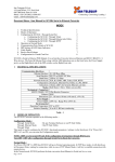
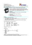
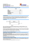
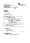
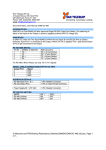
San Telequip (P) Ltd.,
4 Crystal House
235, Navi Peth
Off LBS Road, Pune 411 030, India
Phone : 91-20- 24320023, 24339634/5, 24334423, 65001587
Doc. Name : User Manual : Ethernet Redundant Switch
Connection Scheme :
Connect the Power to the ERS through the 230V AC 3 Pin Plug and Switch On. Power LED glows.
Master LED will glow for a while & then Redundant LED will continuously glow.
Connect your Master port to the Master Port or ERS, your Redundant Slave Port to the Redundant Port
of the ERS & the Common Port of the ERS to your Output device through Straight Cables.
Function – Normally in any network, as per diagram shown below, default Communication will be
through Master port. As soon as data stops coming from Master port, due to some problem or cable
fault, Redundant Ethernet switch automatically senses the failure & changes over to the Redundant
port & starts communicating. The respective LED’s will continuously glow.
When fault is repaired & Data starts coming from Master port it again automatically changeovers to
the Master port & starts communicating.
The Master & the Redundant Input devices on the Network can have the same IP address. We will
connect only the Primary device. The Redundant device will keep getting Network error, till the time
it needs to become active.
Even if the Power supply to the switch is lost or Ethernet Redundant Switch stops responding, default
connectivity will always be ON through Master port.
Block Diagram:
Hardware Specifications :
Power Supply : 230 V AC
Input : RJ 45 : 2 nos.
Output : RJ 45 : 1 nos.
LED Indication : Power / Master /
Redundant.
Speed : 10/100 Mbps.
Size : 105 x 96 x 252mm (wxhxd)