1
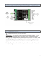
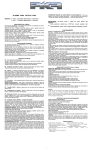
INSTALLATION GUIDE FOR
AO19 LOW ENERGY AUTOMATIC DOOR OPERATOR CONTROL MODULE
B1000S – SUPER SWING
User Manual
Date: July 3, 2008
Note:
This product is a low energy automatic door operator and must be installed /
serviced by a qualified person . The service technician must be familiar with the
latest ANSI /BHMA A156.10/19 standards .
NEVER sacrifice the safe operation of the automatic door for an incomplete
solution. Call the factory for technical support .
P/N 103188
1
AO19 Low Energy Automatic Door Operator Module Description / Connector Pinouts
ISP / Synchronization Connector J 1
ISP – (In System Programmer ) FACTORY USE ONLY
Synchronization – This connector is used to synchronize two modules together (For Dual
door operator ). Synchronization cable , part number 104785. When the synchronization
cable is used , the activation switch (es) can be wired to only one module . All signals , except
for the “Delayed Activation” , are shared between the two modules via the synchronization
cable. When the “Delayed Activation Timer” expires , an activation signal is sent to mate
control.
Note: Using the synchronization cable will not synchronize the door speeds
are kept separately .
. The speeds
2
Signal and Sensor Power Connector – P2
High - Low
Low
Energy
High Energy use and must conform to ANSI/BHMA A156.10
Low
Energy
ANSI/
BHMA
A156 .19
Pin
Signal
Definition
J2.1
Logic ground
J2.2
Activation 1
J2.3
Activation 2
J2.4
Safety A
J2.5
Safety B
When the door is fully closed , this signal to ground will prevent an activation. During the
opening cycle , the door will go to safety speed when this signal is to ground. When the
door is fully opened, this signal to ground will prevent the door from entering the closing
cycle .
J2.6
Delayed Activation
This signal to ground will start the delayed activation timer . When the timer expires, an
activation is generated. This signal is used to do door sequencing.
J2.7
Hold Open
This signal to ground will hold the door opened. If the module is in the ON mode, (Low
voltage ON/OFF must be to ground) and no current fault is present.
J2.8
Low Voltage
ON/OFF
This signal to ground enables the module. This module is disabled if this signal is not to
ground.
J2.9
Data +
This is a signal output for sensor which requires door status information.
When door is closed, Data output is 0V
When door is in the opening cycle, Data output is 12V
When door is closing (in motion), Data output is 8V
J2.10
Logic ground/Data -
Ground reference for signals and power
J2.11
(+24VDC)
DC power to sensors
J2.12
J2.13
(24VAC)
(24VAC)
AC power for sensor
J2.14
Electric lock switch
(Common)
J2.15
Electric lock switch
(normally open)
J2.16
Electric lock switch
(normally close)
Ground reference for signals and power.
This signal to ground will activate the operator. If the module is in the ON mode (Low
voltage ON/OFF must be to ground) and no current fault is present. Note: Manual use of
the door will not enable this input.
This signal is active when the door is in motion . IF the module is in the ON mode (Low
voltage ON/OFF must be to ground) and no current fault is present. Note: Manual use of
the door will not enable this mode.
When the door is fully closed , this signal to ground will prevent an activation. During the
opening cycle (with lockout option to OFF), the door will go to safety speed when this
signal is to ground. During the closing cycle (with lockout position to OFF ), the door will
go to a very slow speed when this signal is to ground. When the door is fully opened, this
signal to ground will prevent the door from entering the closing cycle.
(300mA max.)
This connection is the common to drive an electric lock . (Active when electric lock option
is set to ON)
This connection is the normally open (NO) to drive an electric lock (Active when electric
lock option is set to ON )
This connection is the normally closed (NC) to drive an electric lock (Active when electric
lock option is set to ON )
Power Source (120VAC input connector ) – J3
Pin
Signal Definition
J3.1
AC Line - BLK
J3.2
AC Neutral - WHT
J3.3
AC Ground - GRN
Power required is 120 VAC 50/60 Hz (Maximum current is 3Amperes
3
Refer to ANSI/BHMA A156.10 / 19
4
5
Refer to ANSI /BHMA A156.10 / 19 for more information
6
Refer to ANSI /BHMA A156.10 / 19 for more information
7
Point to Point Dwg for AO19 Low Energy Automatic Door Operator
Refer to ANSI/BHMA A156.10 / 19 for more information, or
Call factory at 1-800-729-3839
24VAC Strike
(if used)
8
Dual Door Operator Sync Cable P /N 104785
For dual door operator , plug Sync Cable P/N 104785 as shown below. When using the Sync
cable, only one control maybe wired to the switches . All signals are shared between the two
controls using the sync cable, except for the “Delayed Activation” input. When the “Delayed
Activation Timer” expires, an activation signal is sent to the mate control
Sensor power can be supplied by both controls for a total of 600mA.
Master Controller
In dual/twin mode, set the
“Activation timer” and “Push & Go
timer” trimmers to the value needed .
Note:
Slave Controller
The Sync cable, P/N 104785 , has two
wires switched at one end of the cable .
Important :
In dual/twin mode, set the
“Activation timer” and “Push & Go
timer” trimmers to the maximum
value (Fully clockwise) for the
slave controller .
Electric lock for twin doors
For one controller to control the electric lock (s), wire the electric lock(s) to one controller. Set the option #3
to “ON” for that controller only . Wire the activation signal(s) to the controller that is wired to the electric
lock.
For two controllers to control the electric locks (to keep the electric locks independent), wire the first lock to
the first controller , the second electric lock to the second controller . Set the option # 3 to “ON” on both
controllers. Wire J2 pin 2 (Activation 1) of the first controller to J 2 pin 2 (Activation 1) of the second
controller.
9