1
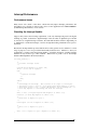
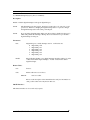
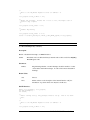
DM5810/DM6810 Driver for Linux
Driver Version 2.0.x User’s Manual
SWM-640010019
rev B
ISO9001 and AS9100 Certified
RTD Embedded Technologies, Inc.
103 Innovation Boulevard
State College, PA 16803-0906
Phone: +1-814-234-8087
FAX: +1-814-234-5218
E-mail
[email protected]
[email protected]
web site
http://www.rtd.com
DM5810/DM6810 Driver for Linux
ii
Revision History
01/17/2005
Revision A issued
Documented for ISO9000
09/29/2005
Revision B issued
Deleted discussion in “Interrupt Performance” section, replacing it with
reference to application note SWM-640000021
DM5810/DM6810 Driver for Linux
Published by:
RTD Embedded Technologies, Inc.
103 Innovation Boulevard
State College, PA 16803-0906
Copyright 2005 by RTD Embedded Technologies, Inc.
All rights reserved
Printed in U.S.A.
The RTD logo and dataModule are registered trademarks of RTD Embedded Technologies.
Linux is a registered trademark of Linus Torvalds. All other trademarks appearing in this document are the property of their respective owners.
iii
DM5810/DM6810 Driver for Linux
Table of Contents
TABLE OF CONTENTS ..............................................................................................................4
INTRODUCTION .........................................................................................................................5
NOTATIONAL CONVENTIONS ...............................................................................................6
INSTALLATION INSTRUCTIONS............................................................................................7
EXTRACTING THE SOFTWARE .......................................................................................................7
CONTENTS OF INSTALLATION DIRECTORY ....................................................................................7
BUILDING THE DRIVER .................................................................................................................7
BUILDING THE LIBRARY ...............................................................................................................8
BUILDING THE EXAMPLE PROGRAMS ...........................................................................................9
INTERRUPT PERFORMANCE ...............................................................................................10
PERFORMANCE ISSUES ...............................................................................................................10
REWRITING THE INTERRUPT HANDLER .......................................................................................10
USING THE API FUNCTIONS.................................................................................................11
FUNCTION REFERENCE ........................................................................................................12
API FUNCTION GROUPS ........................................................................................................13
DIGITAL I/O................................................................................................................................13
GENERAL....................................................................................................................................13
INTERRUPT CONTROL AND STATUS ............................................................................................13
TIMER/COUNTER CONTROL AND STATUS ...................................................................................13
ALPHABETICAL FUNCTION LISTING................................................................................14
EXAMPLE PROGRAMS REFERENCE..................................................................................44
LIMITED WARRANTY.............................................................................................................45
DM5810/DM6810 Driver for Linux
iv
Introduction
This document targets anyone wishing to write Linux applications for an RTD DM5810 or
DM6810 dataModule. It provides information on building the software and about the Application
Programming Interface used to communicate with the hardware and driver. Each high-level
library function is described as well as any low-level ioctl() system call interface it may make use
of.
The diagram below 1) provides a general overview of what hardware and software entities are
involved in device access, 2) shows which units communicate with each other, and 3) illustrates
the methods used to transfer data and control information.
Application
Application
Application
C Function Calls
C Function Calls
C Function Calls
Library
ioctl() System Calls
User Space
Kernel Space
Driver
Software
Memory Accesses
Hardware
Bus
Electrical Signals
Hardware
5
DM5810/DM6810 Driver for Linux
Notational Conventions
RTD Linux drivers are assigned version numbers. These version numbers take the form “A.B.C”
where:
* A is the major release number. This will be incremented whenever major changes are
made to the software. Changing the major release number requires updating the
software manual.
* B is the minor release number. This will be incremented whenever minor, yet
significant, changes are made to the software. Changing the minor release number
requires updating the software manual.
* C is the patch level number. This will be incremented whenever very minor changes
are made to the software. Changing the patch level number does not require updating
the software manual.
In this document, you will see driver version numbers with a letter in them. For example, 2.0.x
indicates that the topic being discussed is applicable to driver versions with a major release
number of 2, a minor release number of 0, and any patch level number.
Occasionally you will notice text placed within the < and > characters, for example
<installation path>. This indicates that the text represents something which depends upon choices
you have made or upon your specific system configuration.
DM5810/DM6810 Driver for Linux
6
Installation Instructions
Extracting the Software
All software comes packaged in a gzip’d tar file named dm6810_Linux_v2.0.x.tar.gz. First,
decide where you would like to place the software. Next, change your current directory to the
directory in which you have chosen to install the software by issuing the command “cd
<installation path>”. Then, extract the software by issuing the “tar -xvzf <path to tar
file>/dm6810_Linux_v2.0.x.tar.gz” command; this will create a directory dm6810_Linux_v2.0.x/
that contains all files comprising the software package.
Contents of Installation Directory
Once the tar file is extracted, you should see the following files and directories within
dm6810_Linux_v2.0.x/:
driver/
examples/
include/
lib/
CHANGES.TXT
LICENSE.TXT
README.TXT
The file CHANGES.TXT describes the changes made to the software for this release, as well as
for previous releases. The file LICENSE.TXT provides details about the RTD end user license
agreement which must be agreed to and accepted before using this software. The file
README.TXT contains a general overview of the software and contact information should you
experience problems, have questions, or need information. The directory driver/ contains the
source code and Makefile for the drivers. The directory examples/ holds the source code and
Makefile for the example programs. The directory include/ contains all header files used by the
driver, example programs, library, and your application programs. Library source code and
Makefile reside in the directory lib/.
Building the Driver
Driver source code uses files located in the kernel source tree. Therefore, you must have the full
kernel source tree available in order to build the driver. The kernel source tree consumes a lot of
disk space, on the order of 100 to 200 megabytes. Because production systems rarely contain this
much disk space, you will probably use a development machine to compile the driver source code.
The development system, which provides a full compilation environment, must be running the
exact same version of the kernel as your production machine(s); otherwise the kernel module may
not load or may load improperly. After the code is built, you can then move the resulting object
files, libraries, and executables to the production system(s).
Building the driver consists of several steps: 1) compiling the source code, 2) loading the
resulting kernel module into the kernel, and 3) creating hardware device files in the /dev directory.
To perform any of the above steps, you must change your current directory to driver/. The file
Makefile contains rules to assist you.
7
DM5810/DM6810 Driver for Linux
To compile the source code, issue the command “make”. The GNU C compiler gcc is used to
build the driver code. This will create the driver object file, which is named rtd-dm6810.o on 2.4
kernels and rtd-dm6810.ko on 2.6 kernels.
Before the driver can be used, it must be loaded into the currently running kernel. Using the
command “make insmod” will load the DM6810 driver into the kernel. This target assumes that:
* A single DM6810 is installed.
* The board's base I/O address is set to the factory default of 0x300.
* The DM6810 is jumpered to use IRQ 5.
If the previous assumptions do not match your hardware setup, you will need to edit the Makefile
and change this rule to reflect your board configuration or manually issue an appropriate insmod
command.
For the 2.4 kernel, when you load the kernel driver the message
"Warning: loading rtd-dm6810.o will taint the kernel: non-GPL license - Proprietary"
will be printed on your screen. You can safely ignore this message since it pertains to GNU
General Public License (GPL) licensing issues rather than to driver operation.
For the 2.6 kernel, when you load the kernel driver, no warnings will appear on your screen.
However, the warning
"module license 'Proprietary' taints kernel."
will be written to the system log when the module is loaded. You can safely ignore this message
since it pertains to GNU General Public License (GPL) licensing issues rather than to driver
operation.
The final step is to create /dev entries for the hardware. Versions of the driver prior to 2.0.0
always assumed a character device major number of 252 when registering the boards and creating
the /dev entries. Instead, the driver now asks the kernel to dynamically assign a major number.
Since this major number may change each time you load the driver, the best way to create the
device files is to use the command "make devices"; this generates four files in /dev named rtddm6810-0 through rtd-dm6810-3.
Be aware that driver/Makefile uses the "uname -r" command to determine which kernel version it
is running on. It does this to set up separate make rules and variables for the 2.4 and 2.6 kernels,
which allows one set of targets to work on both kernels. Compiling the driver on a development
machine which does not run the same kernel version as the production machine that will host your
application almost certainly invites trouble.
If you ever need to unload the driver from the kernel, you can use the command "make rmmod".
Building the Library
The example programs and your application use the DM6810 library, so it must be built before
any of these can be compiled. To build the library, change your current directory to lib/ and issue
the command “make”. The GNU C++ compiler g++ is used to compile the library source code.
To prevent compatibility problems, any source code which makes use of library functions should
also be built with g++.
The DM6810 library is statically linked and is created in the file librtd-dm6810.a.
DM5810/DM6810 Driver for Linux
8
Building the Example Programs
The example programs may be compiled by changing your current directory to examples/ and
issuing the command “make”, which builds all the example programs. If you wish to compile a
subset of example programs, there are targets in Makefile to do so. For example, the command
“make digital-interrupts digital-io interrupt-wait” will compile and link the source files digitalinterrupts.cpp, digital-io.cpp, and interrupt-wait.cpp. The GNU C++ compiler g++ is used to
compile the example program code.
9
DM5810/DM6810 Driver for Linux
Interrupt Performance
Performance Issues
Many factors exist outside of the driver software that may impact interrupt performance and
throughput. For a discussion of these issues, please see the Application Note SWM-640000021
(Linux Interrupt Performance) on our web site.
Rewriting the Interrupt Handler
Suppose that you have the following requirements: 1) the only interrupt being used is the digital
interrupt on port 0/1, 2) whenever a digital interrupt occurs, the value on digital I/O port 2 should
be read, and 3) on digital interrupt occurrence, the value 0x01 should be written to digital I/O port
5. Furthermore, assume the interrupts occur fast enough that dealing with them in user space is
unreliable.
Because the interrupt handler provided with the driver offers generic services suitable for a wide
range of purposes, it does not provide the functionality indicated above. Therefore to meet your
requirements, you must rewrite the interrupt handler. A detailed description of writing interrupt
handlers lies beyond the scope of this document. What follows is pseudo code for an interrupt
handler which implements the desired behavior.
interrupt_handler() {
/*
* Determine interrupt status
*/
read IRQ Status Register at offset 0x11;
if bit 0 is not set in register
then
/*
* Spurious interrupt
*/
exit;
end if
/*
* Acknowledge the interrupt. This consists of two steps: 1) writing the
* appropriate value to the Port 0/1 Program Digital Mode Register to select
* clear mode access to Port 0/1 Clear IRQ Register, and 2) reading Port 0/1
* Clear IRQ Register to acknowledge and clear the interrupt.
*/
write to Port 0/1 Program Digital Mode Register at offset 0x03;
read Port 0/1 Clear IRQ Register at offset 0x02;
/*
* Read value on digital I/O port 2
*/
read Digital I/O Port 2 Register at offset 0x04;
/*
* Write 0x01 to digital I/O port 5
*/
write 0x01 to Digital I/O port 5 Register at offset 0x09;
}
DM5810/DM6810 Driver for Linux
10
Using the API Functions
DM6810 hardware and the associated driver functionality can be accessed through the library API
(Application Programming Interface) functions. Applications wishing to use library functions
must include the include/dm6810_library.h header file and be statically linked with the lib/librtddm6810.a library file.
Because of changes made in driver version 2.0.0, existing source code which uses the library will
not compile. Some of the areas requiring attention on your part are:
* All header files have been renamed. Users upgrading from a previous driver version will
need to modify source code to include the appropriate header files.
* All header files have been relocated to include/. Be sure to update any files which contain
hardcoded header file paths.
* 6810 has been appended to all library function names with the exception of class
constructors and destructors.
* Library functions which accepted a digital I/O chip number now accept a digital I/O port
number.
* Interrupt notification via signals is no longer supported. The new notification paradigm
provides a function which can block in the kernel until an interrupt occurs.
* The driver now acknowledges all interrupts in the interrupt handler. Therefore, interrupt
status is no longer available to an application through certain functions.
* All classes have been coalesced into a single class DM6810Device.
* The DM6810 /dev entry file names have changed. For example, the device file previously
named /dev/rtd/dm6810hr/device0 is now called /dev/rtd-dm6810-0.
The following function reference provides for each library routine a prototype, description,
explanation of parameters, and return value or error code. By looking at a function’s entry, you
should gain an idea of: 1) why it would be used, 2) what it does, 3) what information is passed
into it, 4) what information it passes back, 5) how to interpret error conditions that may arise, and
6) the ioctl() system call interface if the function makes use of a single ioctl() call.
Note that errno codes other than the ones indicated in the following pages may be set by the
library functions. Please see the ioctl(2) man page for more information.
11
DM5810/DM6810 Driver for Linux
Function Reference
DM5810/DM6810 Driver for Linux
12
API Function Groups
Digital I/O
DIOClearChip6810
DIOClearIrq6810
DIOClearStrobe6810
DIOEnableIrq6810
DIOIsIrq6810
DIOIsIRQ6810
DIOIsStrobe6810
DIORead6810
DIOSelectClock6810
DIOSelectRegister6810
DIOSetIRQSource6810
DIOSetPortDirection6810
DIOStrobeEnable6810
DIOWrite6810
General
CloseBoard6810
DM6810Device
~DM6810Device
GetDriverVersion6810
InitBoard6810
OpenBoard6810
ReadByte6810
WriteByte6810
Interrupt Control and Status
ClearP14IRQ6810
EnableIRQSharing6810
EnableP14IRQ6810
GetIRQStatus6810
GetLastIntStatus6810
IsP14IRQ6810
LoadIRQRegister6810
SetP14IRQPolarity6810
Timer/Counter Control and Status
ClockDivisor6810
ClockMode6810
DoneTimer6810
ReadTimerCounter6810
SetUserClock6810
13
DM5810/DM6810 Driver for Linux
Alphabetical Function Listing
ClearP14IRQ6810
void ClearP14IRQ6810(void);
Description:
Clear a DM6810 device's P14 interrupt status flag. This will acknowledge a P14 interrupt which
has occurred.
NOTE:
There is no need to call this function from an application. Interrupts are
automatically acknowledged by the driver's interrupt handler.
Parameters:
None.
Return Value:
None.
IOCTL Interface:
dm6810_ioctl_argument_t ioctl_request;
int file_descriptor;
int status;
/*
* Before calling ioctl(), file_descriptor must be set up.
* here.
*/
This is not shown
/*
* Read the Clear IRQ Register at base I/O address + 16
*/
ioctl_request.access_8.offset = 0x10;
/*
* This value does not matter because it is ignored making the request
*/
ioctl_request.access_8.data = 0;
status = ioctl(file_descriptor, DM6810_IOCTL_READ_8_BITS, &ioctl_request);
ClockDivisor6810
bool ClockDivisor6810(u_int8_t Timer, u_int16_t Divisor);
Description:
Set the divisor for the given 8254 timer/counter.
NOTE:
Before calling this function, you must ensure that the indicated timer/counter is set
to be programmed least significant byte first then most significant byte.
DM5810/DM6810 Driver for Linux
14
Parameters:
Timer:
The timer to operate on. Valid values are:
0 Timer/counter 0
1 Timer/counter 1
2 Timer/counter 2
Divisor:
Counter divisor. Valid values are 0 through 65535.
Return Value:
true:
Success.
false:
Failure with errno set as follows:
EINVAL
Timer is not valid.
Please see the description of the internal function outb() for information on
other possible values errno may have in this case.
IOCTL Interface:
This function makes use of several ioctl() requests.
ClockMode6810
bool ClockMode6810(u_int8_t Timer, u_int8_t Mode);
Description:
Set the mode for the given 8254 timer/counter.
NOTE:
This function puts the indicated timer/counter into binary mode.
NOTE:
This function sets the timer/counter to read/load least significant byte first then most
significant byte.
Parameters:
15
Timer:
The timer to operate on. Valid values are:
0 Timer/counter 0
1 Timer/counter 1
2 Timer/counter 2
Mode:
The counter mode to set. Valid values are:
0 Event count
1 Programmable one shot
2 Rate generator
3 Square wave rate generator
4 Software triggered strobe
5 Hardware triggered strobe
DM5810/DM6810 Driver for Linux
Return Value:
true:
Success.
false:
Failure with errno set as follows:
EINVAL
Timer is not valid.
EINVAL
Mode is not valid.
Please see the description of the internal function outb() for information on
other possible values errno may have in this case.
IOCTL Interface:
dm6810_ioctl_argument_t ioctl_request;
int file_descriptor;
int status;
/*
* Before calling ioctl(), file_descriptor must be set up.
* here.
*/
This is not shown
/*
* Write to the 8254 Timer/Counter Control Word Register at base I/O address + 15
*/
ioctl_request.access_8.offset = 0x0F;
/*
* Set timer to read/load least significant byte first then most significant
* byte. Because bit 0 is set to zero, this puts the timer in binary mode.
*/
ioctl_request.access_8.data = 0x30;
/*
* Operate on timer/counter 1
*/
ioctl_request.access_8.offset |= 0x40;
/*
* Put timer in rate generator mode
*/
ioctl_request.access_8.offset |= 0x04;
status = ioctl(file_descriptor, DM6810_IOCTL_WRITE_8_BITS, &ioctl_request);
CloseBoard6810
bool CloseBoard6810(void);
Description:
Close a DM6810 device file.
DM5810/DM6810 Driver for Linux
16
Parameters:
None.
Return Value:
true:
Success.
false:
Failure. Please see the close(2) man page for information on possible
values errno may have in this case.
IOCTL Interface:
None.
DIOClearChip6810
bool DIOClearChip6810(u_int8_t Port);
Description:
Clear the digital I/O chip for the given digital I/O port.
NOTE:
The digital I/O ports exist in pairs. Ports 0 & 1 form a pair, as do ports 2 & 3, and
ports 4 & 5. Therefore, clearing the digital I/O chip for a port also clears the digital
I/O chip for the other port in the pair.
Parameters:
Port:
Digital I/O port for which to clear chip. Valid values are:
0 Digital I/O port 0
1 Digital I/O port 1
2 Digital I/O port 2
3 Digital I/O port 3
4 Digital I/O port 4
5 Digital I/O port 5
Return Value:
true:
Success.
false:
Failure with errno set as follows:
EINVAL
Port is not valid.
Please see the descriptions of the internal functions outb() and
select_dio_control_register() for information on other possible values errno
may have in this case.
IOCTL Interface:
This function makes use of several ioctl() requests.
17
DM5810/DM6810 Driver for Linux
DIOClearIrq6810
bool DIOClearIrq6810(u_int8_t Port);
Description:
Clear the Digital IRQ Status bit for the given digital I/O port.
NOTE:
The digital I/O ports exist in pairs. Ports 0 & 1 form a pair, as do ports 2 & 3, and
ports 4 & 5. Therefore, clearing the Digital IRQ Status bit for a port also clears the
Digital IRQ Status bit for the other port in the pair.
NOTE:
There is no need to call this function from an application. Interrupts are
automatically acknowledged by the driver's interrupt handler.
Parameters:
Port:
Digital I/O port to clear IRQ status of. Valid values are:
0 Digital I/O port 0
1 Digital I/O port 1
2 Digital I/O port 2
3 Digital I/O port 3
4 Digital I/O port 4
5 Digital I/O port 5
Return Value:
true:
Success.
false:
Failure with errno set as follows:
EINVAL
Port is not valid.
Please see the description of the internal function
select_dio_control_register() for information on other possible values errno
may have in this case.
IOCTL Interface:
This function makes use of several ioctl() requests.
DIOClearStrobe6810
bool DIOClearStrobe6810(u_int8_t Port);
Description:
Clear the Strobe Status bit in the Read Digital I/O Status Register for the given digital I/O port.
NOTE:
The digital I/O ports exist in pairs. Ports 0 & 1 form a pair, as do ports 2 & 3, and
ports 4 & 5. Therefore, clearing the Strobe Status bit for a port also clears the
Strobe Status bit for the other port in the pair.
DM5810/DM6810 Driver for Linux
18
NOTE:
DIOClearChip6810() does not clear the Strobe Status bit. During program
initialization, DIOClearStrobe6810() must be called to ensure that the bit is cleared.
Once data is being strobed into an even-numbered port, reading data from that port
will clear the Strobe Status flag.
NOTE:
Even though this function accepts an odd-numbered port, it is internally translated
into the even-numbered port in the pair since only the even-numbered ports support
data strobing.
Parameters:
Port:
Digital I/O port to clear strobe status of. Valid values are:
0 Digital I/O port 0
1 Digital I/O port 1
2 Digital I/O port 2
3 Digital I/O port 3
4 Digital I/O port 4
5 Digital I/O port 5
Return Value:
true:
Success.
false:
Failure with errno set as follows:
EINVAL
Port is not valid.
IOCTL Interface:
dm6810_ioctl_argument_t ioctl_request;
int file_descriptor;
int status;
/*
* Before calling ioctl(), file_descriptor must be set up.
* here.
*/
This is not shown
/*
* Read the Digital I/O Port 0 Register at base I/O address + 0
*/
ioctl_request.access_8.offset = 0x00;
/*
* This value does not matter because it is ignored making the request
*/
ioctl_request.access_8.data = 0;
status = ioctl(file_descriptor, DM6810_IOCTL_READ_8_BITS, &ioctl_request);
19
DM5810/DM6810 Driver for Linux
DIOEnableIrq6810
bool DIOEnableIrq6810(u_int8_t Port, bool Enable);
Description:
Enable or disable digital interrupts for the given digital I/O port.
NOTE:
The digital I/O ports exist in pairs. Ports 0 & 1 form a pair, as do ports 2 & 3, and
ports 4 & 5. Therefore, changing the digital interrupt state for a port also changes
the digital interrupt state for the other port in the pair.
NOTE:
If you are using digital interrupts, make sure data strobing is disabled for the port(s)
which will generate the interrupts. Having data strobe enabled for a port disables
digital interrupts for that port.
Parameters:
Port:
Digital I/O port to modify interrupt state for. Valid values are:
0 Digital I/O port 0
1 Digital I/O port 1
2 Digital I/O port 2
3 Digital I/O port 3
4 Digital I/O port 4
5 Digital I/O port 5
Enable:
Flag indicating whether or not digital interrupts should be enabled. A value
of true means enable digital interrupts. A value of false means disable
digital interrupts.
Return Value:
true:
Success.
false:
Failure with errno set as follows:
EINVAL
Port is not valid.
Please see the description of the internal function outb() for information on
other possible values errno may have in this case.
IOCTL Interface:
This function makes use of several ioctl() requests.
DM5810/DM6810 Driver for Linux
20
DIOIsIRQ6810
bool DIOIsIRQ6810(u_int8_t Port);
Description:
Determine whether or not the given digital I/O port generated an interrupt.
NOTE:
The digital I/O ports exist in pairs. Ports 0 & 1 form a pair, as do ports 2 & 3, and
ports 4 & 5. Therefore, the interrupt state for a port is indistinguishable from the
interrupt state for the other port in the pair.
NOTE:
This function examines the contents of the IRQ Status Register at base I/O address +
17.
NOTE:
This function is equivalent to DIOIsIrq6810().
NOTE:
The information returned by this function is unreliable because the driver's interrupt
handler clears all interrupt status flags during interrupt acknowledgement.
Parameters:
Port:
Digital I/O port to examine interrupt status of. Valid values are:
0 Digital I/O port 0
1 Digital I/O port 1
2 Digital I/O port 2
3 Digital I/O port 3
4 Digital I/O port 4
5 Digital I/O port 5
Return Value:
false:
No interrupt occurred.
true:
An interrupt occurred.
IOCTL Interface:
dm6810_ioctl_argument_t ioctl_request;
int file_descriptor;
int status;
/*
* Before calling ioctl(), file_descriptor must be set up.
* here.
*/
This is not shown
/*
* Read the IRQ Status Register at base I/O address + 17
*/
ioctl_request.access_8.offset = 0x11;
21
DM5810/DM6810 Driver for Linux
/*
* This value does not matter because it is ignored making the request.
* However after ioctl() returns, the structure member will contain the
* register contents.
*/
ioctl_request.access_8.data = 0;
status = ioctl(file_descriptor, DM6810_IOCTL_READ_8_BITS, &ioctl_request);
if (status == 0) {
/*
* If bit 0 is set, then interrupt occurred on port 0/1
*/
if (ioctl_request.access_8.data & 0x01) {
fprintf(stdout, “Digital I/O port 0/1 generated an interrupt\n”);
}
}
DIOIsIrq6810
bool DIOIsIrq6810(u_int8_t Port);
Description:
Determine whether or not the given digital I/O port generated an interrupt.
NOTE:
The digital I/O ports exist in pairs. Ports 0 & 1 form a pair, as do ports 2 & 3, and
ports 4 & 5. Therefore, the interrupt state for a port is indistinguishable from the
interrupt state for the other port in the pair.
NOTE:
This function examines the contents of the port's Read Port Digital I/O Status
Register.
NOTE:
This function is equivalent to DIOIsIRQ6810().
NOTE:
The information returned by this function is unreliable because the driver's interrupt
handler clears all interrupt status flags during interrupt acknowledgement.
Parameters:
Port:
Digital I/O port to examine interrupt status of. Valid values are:
0 Digital I/O port 0
1 Digital I/O port 1
2 Digital I/O port 2
3 Digital I/O port 3
4 Digital I/O port 4
5 Digital I/O port 5
Return Value:
false:
No interrupt occurred.
true:
An interrupt occurred.
DM5810/DM6810 Driver for Linux
22
IOCTL Interface:
dm6810_ioctl_argument_t ioctl_request;
int file_descriptor;
int status;
/*
* Before calling ioctl(), file_descriptor must be set up.
* here.
*/
This is not shown
/*
* Read the Port 2/3 Digital I/O Status Register at base I/O address + 7
*/
ioctl_request.access_8.offset = 0x07;
/*
* This value does not matter because it is ignored making the request.
* However after ioctl() returns, the structure member will contain the
* register contents.
*/
ioctl_request.access_8.data = 0;
status = ioctl(file_descriptor, DM6810_IOCTL_READ_8_BITS, &ioctl_request);
if (status == 0) {
/*
* If bit 7 is set, then interrupt occurred on port 2/3
*/
if (ioctl_request.access_8.data & 0x80) {
fprintf(stdout, “Digital I/O port 2/3 generated an interrupt\n”);
}
}
DIOIsStrobe6810
bool DIOIsStrobe6810(u_int8_t Port);
Description:
Determine whether or not data has been strobed into the given digital I/O port.
NOTE:
The digital I/O ports exist in pairs. Ports 0 & 1 form a pair, as do ports 2 & 3, and
ports 4 & 5. Therefore, the strobe state for a port is indistinguishable from the
strobe state for the other port in the pair.
NOTE:
Only the even-numbered ports support data strobing.
Parameters:
Port:
23
Digital I/O port to examine strobe status of. Valid values are:
0 Digital I/O port 0
1 Digital I/O port 1
2 Digital I/O port 2
3 Digital I/O port 3
4 Digital I/O port 4
5 Digital I/O port 5
DM5810/DM6810 Driver for Linux
Return Value:
false:
Data not strobed.
true:
Data strobed.
IOCTL Interface:
dm6810_ioctl_argument_t ioctl_request;
int file_descriptor;
int status;
/*
* Before calling ioctl(), file_descriptor must be set up.
* here.
*/
This is not shown
/*
* Read the Port 4/5 Digital I/O Status Register at base I/O address + 11
*/
ioctl_request.access_8.offset = 0x0B;
/*
* This value does not matter because it is ignored making the request.
* However after ioctl() returns, the structure member will contain the
* register contents.
*/
ioctl_request.access_8.data = 0;
status = ioctl(file_descriptor, DM6810_IOCTL_READ_8_BITS, &ioctl_request);
if (status == 0) {
/*
* If bit 6 is set, then data strobe occurred on port 4
*/
if (ioctl_request.access_8.data & 0x40) {
fprintf(stdout, “Data strobed into digital I/O port 4\n”);
}
}
DIORead6810
u_int8_t DIORead6810(u_int8_t Port);
Description:
Read an 8-bit value from the given digital I/O port.
Parameters:
Port:
The port to read from. Value values are:
0 Digital I/O port 0
1 Digital I/O port 1
2 Digital I/O port 2
3 Digital I/O port 3
4 Digital I/O port 4
5 Digital I/O port 5
DM5810/DM6810 Driver for Linux
24
Return Value:
8-bit value from specified digital I/O port.
IOCTL Interface:
dm6810_ioctl_argument_t ioctl_request;
int file_descriptor;
int status;
/*
* Before calling ioctl(), file_descriptor must be set up.
* here.
*/
This is not shown
/*
* Read the Digital I/O Port 1 Register at base I/O address + 1
*/
ioctl_request.access_8.offset = 0x01;
/*
* This value does not matter because it is ignored making the request.
* However after ioctl() returns, the structure member will contain the
* register contents.
*/
ioctl_request.access_8.data = 0;
status = ioctl(file_descriptor, DM6810_IOCTL_READ_8_BITS, &ioctl_request);
if (status == 0) {
fprintf(stdout, “Port 1 input: 0x%x\n”, ioctl_request.access_8.data);
}
DIOSelectClock6810
bool DIOSelectClock6810(u_int8_t Port, bool Programmable);
Description:
Select sampling clock for the given digital I/O port.
NOTE:
The digital I/O ports exist in pairs. Ports 0 & 1 form a pair, as do ports 2 & 3, and
ports 4 & 5. Therefore, setting the sampling clock for a port also sets the same
sampling clock for the other port in the pair.
Parameters:
25
Port:
Port to set clock for. Valid values are:
0 Digital I/O port 0
1 Digital I/O port 1
2 Digital I/O port 2
3 Digital I/O port 3
4 Digital I/O port 4
5 Digital I/O port 5
Programmable:
Flag to indicate whether or not 8254 Timer/Counter 1 should be
used. A value of false means use the 8 MHz system clock. A
value of true mean use the 8254 Timer/Counter 1.
DM5810/DM6810 Driver for Linux
Return Value:
true:
Success.
false:
Failure with errno set as follows:
EINVAL
Port is not valid.
Please see the description of the internal function outb() for information on
other possible values errno may have in this case.
IOCTL Interface:
This function makes use of several ioctl() requests.
DIOSelectRegister6810
bool DIOSelectRegister6810(u_int8_t Port, u_int8_t Select);
Description:
Select which control register is accessed for the given digital I/O port.
NOTE:
This function is not normally required in an application. The other library functions
which require digital I/O control register access select that register internally.
Parameters:
Port:
The port to select control register for. Value values are:
0 Digital I/O port 0
1 Digital I/O port 1
2 Digital I/O port 2
3 Digital I/O port 3
4 Digital I/O port 4
5 Digital I/O port 5
Select:
Control register to access. Valid values are:
0 Clear Register
1 Even-numbered Port Direction Register
2 Odd-numbered Port Direction Register
3 IRQ Source Register
Return Value:
true:
Success.
false:
Failure with errno set as follows:
EINVAL
Port is not valid.
EINVAL
Select is not valid.
DM5810/DM6810 Driver for Linux
26
Please see the description of the internal function
select_dio_control_register() for information on other possible values errno
may have in this case.
IOCTL Interface:
This function makes use of several ioctl() requests.
DIOSetIRQSource6810
bool DIOSetIRQSource6810(u_int8_t Port, u_int8_t Bit);
Description:
Set which bit generates a digital interrupt for the given digital I/O port.
NOTE:
The digital I/O ports exist in pairs. Ports 0 & 1 form a pair, as do ports 2 & 3, and
ports 4 & 5. Therefore, changing the digital interrupt source for a port will
overwrite any digital interrupt source set for the other port in the pair.
Parameters:
Port:
Port to set digital interrupt source for. Valid values are:
0 Digital I/O port 0
1 Digital I/O port 1
2 Digital I/O port 2
3 Digital I/O port 3
4 Digital I/O port 4
5 Digital I/O port 5
Bit:
The bit which generates a digital interrupt. Valid values are:
0 Bit 0
1 Bit 1
2 Bit 2
3 Bit 3
4 Bit 4
5 Bit 5
6 Bit 6
7 Bit 7
Return Value:
27
true:
Success.
false:
Failure with errno set as follows:
EINVAL
Port is not valid.
EINVAL
Bit is not valid.
DM5810/DM6810 Driver for Linux
Please see the description of the internal functions outb() and
select_dio_control_register() for information on other possible values errno
may have in this case.
IOCTL Interface:
This function makes use of several ioctl() requests.
DIOSetPortDirection6810
bool DIOSetPortDirection6810(u_int8_t Port, u_int8_t Direction);
Description:
Set the direction (input or output) for the bits in the given digital I/O port.
Parameters:
Port:
Port to set bit direction for. Valid values are:
0 Digital I/O port 0
1 Digital I/O port 1
2 Digital I/O port 2
3 Digital I/O port 3
4 Digital I/O port 4
5 Digital I/O port 5
Direction:
Bit mask which controls bit direction. A zero in a bit position means
the corresponding port bit is set to input. A one in a bit position means
the corresponding port bit is set to output.
Return Value:
true:
Success.
false:
Failure with errno set as follows:
EINVAL
Port is not valid.
Please see the description of the internal functions outb() and
select_dio_control_register() for information on other possible values errno
may have in this case.
IOCTL Interface:
This function makes use of several ioctl() requests.
DM5810/DM6810 Driver for Linux
28
DIOStrobeEnable6810
bool DIOStrobeEnable6810(u_int8_t Port, bool Enable);
Description:
Enable or disable data strobing for the given digital I/O port.
NOTE:
The digital I/O ports exist in pairs. Ports 0 & 1 form a pair, as do ports 2 & 3, and
ports 4 & 5. Therefore, changing the data strobe state for a port also changes the
data strobe state for the other port in the pair.
NOTE:
Only the even-numbered ports support data strobing.
Parameters:
Port:
Port to set data strobing for. Valid values are:
0 Digital I/O port 0
1 Digital I/O port 1
2 Digital I/O port 2
3 Digital I/O port 3
4 Digital I/O port 4
5 Digital I/O port 5
Enable:
Flag indicating whether or not data strobe should be enabled. A value of
true means enable data strobe. A value of false means disable data strobe.
Return Value:
true:
Success.
false:
Failure with errno set as follows:
EINVAL
Port is not valid.
Please see the description of the internal function outb() for information on
other possible values errno may have in this case.
IOCTL Interface:
This function makes use of several ioctl() requests.
DIOWrite6810
bool DIOWrite6810(u_int8_t Port, u_int8_t Data);
Description:
Write an 8-bit value to the given digital I/O port.
29
DM5810/DM6810 Driver for Linux
Parameters:
Port:
The port to write to. Value values are:
0 Digital I/O port 0
1 Digital I/O port 1
2 Digital I/O port 2
3 Digital I/O port 3
4 Digital I/O port 4
5 Digital I/O port 5
Data:
Data to write. Valid values are 0 through 255.
Return Value:
true:
Success.
false:
Failure with errno set as follows:
EINVAL
Port is not valid.
Please see the description of the internal function outb() for information on
other possible values errno may have in this case.
IOCTL Interface:
dm6810_ioctl_argument_t ioctl_request;
int file_descriptor;
int status;
/*
* Before calling ioctl(), file_descriptor must be set up.
* here.
*/
This is not shown
/*
* Write to the Digital I/O Port 3 Register at base I/O address + 5
*/
ioctl_request.access_8.offset = 0x05;
/*
* Write a value with bits 4 through 7 set to one
*/
ioctl_request.access_8.data = 0xF0;
status = ioctl(file_descriptor, DM6810_IOCTL_WRITE_8_BITS, &ioctl_request);
DM6810Device
DM6810Device(void);
Description:
DM6810Device class constructor.
DM5810/DM6810 Driver for Linux
30
Parameters:
None.
Return Value:
None. Constructors do not return a value.
IOCTL Interface:
None.
~DM6810Device
~DM6810Device(void);
Description:
DM6810Device class destructor.
Parameters:
None.
Return Value:
None. Destructors do not return a value.
IOCTL Interface:
None.
DoneTimer6810
bool DoneTimer6810(void);
Description:
Set each timer/counter into rate generator mode and load each with a divisor value of two.
Parameters:
None.
31
DM5810/DM6810 Driver for Linux
Return Value:
true:
Success.
false:
Failure. Please see the descriptions of ClockMode6810() and
ClockDivisor6810() for information on possible values errno may have in
this case.
IOCTL Interface:
This function makes use of several ioctl() requests.
EnableIRQSharing6810
bool EnableIRQSharing6810(u_int8_t Enable);
Description:
Enable or disable a board's interrupt sharing feature.
NOTE:
This function also modifies the library's internal cache of the board's Clear IRQ/IRQ
Enable Register value.
NOTE:
The DM6810 interrupt handler is not designed to process interrupts shared between
devices. To avoid unpredictable behavior or worse, do not share an interrupt
between devices.
NOTE:
Interrupts do not need to be shared in order to use several interrupt sources on a
single board. For example if you wish to use both P14 and port 0 digital interrupts
on a single DM6810 device, then interrupts do not need to be shared.
Parameters:
Enable:
Flag indicating whether or not interrupt sharing should be enabled. A
value of 0 means disable interrupt sharing. Any other value means enable
interrupt sharing.
Return Value:
true:
Success.
false:
Failure. Please see the description of the internal function outb() for
information on possible values errno may have in this case.
IOCTL Interface:
dm6810_ioctl_argument_t ioctl_request;
int file_descriptor;
int status;
/*
* Before calling ioctl(), file_descriptor must be set up.
* here.
*/
DM5810/DM6810 Driver for Linux
This is not shown
32
/*
* Write to the IRQ Enable Register at base I/O address + 16
*/
ioctl_request.access_8.offset = 0x10;
/*
* Enable P14 interrupt. Because bit 1 is set to zero, interrupts occur on
* positive edge of pulse.
*/
ioctl_request.access_8.data = 0x01;
/*
* Disable IRQ sharing
*/
ioctl_request.access_8.data |= 0x04;
status = ioctl(file_descriptor, DM6810_IOCTL_WRITE_8_BITS, &ioctl_request);
EnableP14IRQ6810
bool EnableP14IRQ6810(bool Enable);
Description:
Enable or disable P14 interrupts on a DM6810 device.
NOTE:
This function also modifies the library's internal cache of the board's Clear IRQ/IRQ
Enable Register value.
Parameters:
Enable:
Flag indicating whether or not P14 interrupts should be enabled. A value
of true means enable P14 interrupts. A value of false means disable P14
interrupts.
Return Value:
true:
Success.
false:
Failure. Please see the description of the internal function outb() for
information on possible values errno may have in this case.
IOCTL Interface:
dm6810_ioctl_argument_t ioctl_request;
int file_descriptor;
int status;
/*
* Before calling ioctl(), file_descriptor must be set up.
* here.
*/
This is not shown
/*
* Write to the IRQ Enable Register at base I/O address + 16
*/
ioctl_request.access_8.offset = 0x10;
33
DM5810/DM6810 Driver for Linux
/*
* Disable P14 interrupt (bit 0 == 0) and disable IRQ sharing (bit 2 == 1)
*/
ioctl_request.access_8.data = 0x04;
status = ioctl(file_descriptor, DM6810_IOCTL_WRITE_8_BITS, &ioctl_request);
GetDriverVersion6810
bool GetDriverVersion6810(u_int32_t *version_p);
Description:
Get the driver version number. The version number is an unsigned integer encoding the major,
minor, and patch level numbers.
NOTE:
The driver version is encoded according to the formula
Version = (
(MajorVersion << 16)
|
(MinorVersion << 8)
|
PatchLevelNumber
)
Parameters:
version_p:
Address where version number should be stored. If this is NULL, then
no version number is returned. This location is unchanged if the
function fails.
Return Value:
true:
Success.
false:
version_p is NULL.
Failure. Please see the ioctl(2) man page for information on possible values errno
may have in this case.
IOCTL Interface:
dm6810_ioctl_argument_t ioctl_request;
int file_descriptor;
int status;
/*
* Before calling ioctl(), file_descriptor must be set up.
* here.
*/
This is not shown
status = ioctl(file_descriptor, DM6810_IOCTL_GET_DRIVER_VERSION, &ioctl_request);
DM5810/DM6810 Driver for Linux
34
if (status == 0) {
u_int32_t version;
version = ioctl_request.version.driver_version;
fprintf(stdout, “Major version: %d\n”, ((version >> 16) & 0xF));
fprintf(stdout, “Minor version: %d\n”, ((version >> 8) & 0xF));
fprintf(stdout, “Patch level: %d\n”, (version & 0xF));
}
GetIRQStatus6810
u_int8_t GetIRQStatus6810(void);
Description:
Get the contents of a board's IRQ Status Register at base I/O address + 17.
NOTE:
Only bits 0 through 3 are returned.
NOTE:
The information returned by this function is unreliable because the driver's interrupt
handler clears all interrupt status flags during interrupt acknowledgement.
Parameters:
None.
Return Value:
IRQ Status Register contents. Please see the hardware manual for the interpretation of
register bits.
IOCTL Interface:
dm6810_ioctl_argument_t ioctl_request;
int file_descriptor;
int status;
/*
* Before calling ioctl(), file_descriptor must be set up.
* here.
*/
This is not shown
/*
* Read the IRQ Status Register at base I/O address + 17
*/
ioctl_request.access_8.offset = 0x11;
/*
* This value does not matter because it is ignored making the request.
* However after ioctl() returns, the structure member will contain the
* register contents.
*/
ioctl_request.access_8.data = 0;
status = ioctl(file_descriptor, DM6810_IOCTL_READ_8_BITS, &ioctl_request);
if (status == 0) {
fprintf(stdout, “IRQ Status: 0x%x\n”, (ioctl_request.access_8.data & 0xF));
}
35
DM5810/DM6810 Driver for Linux
GetLastIntStatus6810
bool GetLastIntStatus6810(
u_int32_t *int_count_p,
u_int8_t *status_reg_p,
bool wait_for_interrupt
);
Description:
Get the driver's interrupt count and IRQ Status Register value at the time of the most recent
interrupt.
NOTE:
This function can be used to provide interrupt notification if wait_for_interrupt is set
to true. In this case, the function does not exit the kernel until the driver's interrupt
handler wakes the process up.
NOTE:
If wait_for_interrupt is true, this function will always wait for the next interrupt to
occur even if an interrupt just happened.
NOTE:
Only bits 0 through 3 in the IRQ Status Register are returned.
NOTE:
If you are using this function to wait for interrupts, signals can wake up the process
before an interrupt occurs. If a signal is delivered to the process during a wait, no
status or count is returned and the application is responsible for dealing with the
premature awakening in a reasonable manner.
Parameters:
int_count_p:
Address where interrupt count should be stored. Nothing is
written here if the function fails.
status_reg_p:
Address where Status Register value should be stored.
Nothing is written here if the function fails.
wait_for_interrupt:
Flag indicating whether or not to wait for an interrupt to occur
before returning status. A value of false means return the
most recent interrupt status without waiting. A value of true
means wait for an interrupt to occur and then return status.
Return Value:
true:
Success.
false:
Failure with errno set as follows:
EINTR
The process received a signal before an interrupt occurred.
Please see the ioctl(2) man page for information on other possible values
errno may have in this case.
DM5810/DM6810 Driver for Linux
36
IOCTL Interface:
dm6810_ioctl_argument_t ioctl_request;
int file_descriptor;
int status;
/*
* Before calling ioctl(), file_descriptor must be set up.
* here.
*/
This is not shown
/*
* Wait in the kernel until the next interrupt occurs before returning status
*/
ioctl_request.last_int_status.wait_for_interrupt = 0xFF;
/*
* These values do not matter because they are ignored making the request.
* However after ioctl() returns, the structure members will contain the
* requested information.
*/
ioctl_request.last_int_status.status_reg = 0;
ioctl_request.last_int_status.int_count = 0;
status = ioctl(
file_descriptor, DM6810_IOCTL_GET_LAST_INT_STATUS, &ioctl_request
);
if (status == 0) {
fprintf(stdout, “Status at last interrupt:\n”);
fprintf(
stdout, “
IRQ Status: 0x%x\n”, ioctl_request.last_int_status.status_reg
);
fprintf(
stdout, “
# interrupts: %d\n”, ioctl_request.last_int_status.int_count
);
}
InitBoard6810
void InitBoard6810(void);
Description:
Initialize DM6810 device class library state. This consists of clearing the library's internal cache
of the board's Clear IRQ/IRQ Enable Register value.
NOTE:
This function does not update the board's Clear IRQ/IRQ Enable Register.
Parameters:
None.
Return Value:
None.
IOCTL Interface:
None.
37
DM5810/DM6810 Driver for Linux
IsP14IRQ6810
bool IsP14IRQ6810(void);
Description:
Determine whether or not a board's interrupt circuit generated a P14 interrupt.
NOTE:
The information returned by this function is unreliable because the driver's interrupt
handler clears all interrupt status flags during interrupt acknowledgement.
Parameters:
None.
Return Value:
false:
No interrupt occurred.
true:
An interrupt occurred.
IOCTL Interface:
dm6810_ioctl_argument_t ioctl_request;
int file_descriptor;
int status;
/*
* Before calling ioctl(), file_descriptor must be set up.
* here.
*/
This is not shown
/*
* Read the IRQ Status Register at base I/O address + 17
*/
ioctl_request.access_8.offset = 0x11;
/*
* This value does not matter because it is ignored making the request.
* However after ioctl() returns, the structure member will contain the
* register contents.
*/
ioctl_request.access_8.data = 0;
status = ioctl(file_descriptor, DM6810_IOCTL_READ_8_BITS, &ioctl_request);
if (status == 0) {
if (ioctl_request.access_8.data & 0x08) {
fprintf(stdout, “P14 interrupt occurred\n”);
}
}
LoadIRQRegister6810
bool LoadIRQRegister6810(u_int8_t Value);
Description:
Load an 8-bit value into a board's Clear IRQ/IRQ Enable Register at base I/O address + 16.
DM5810/DM6810 Driver for Linux
38
NOTE:
This function also sets the library's internal cache of the board's Clear IRQ/IRQ
Enable Register value.
Parameters:
Value:
Value to store in register. Valid values are 0 through 7. Please see the
hardware manual for the interpretation of the register's bits.
Return Value:
true:
Success.
false:
Failure. Please see the description of the internal function outb() for
information on possible values errno may have in this case.
IOCTL Interface:
dm6810_ioctl_argument_t ioctl_request;
int file_descriptor;
int status;
/*
* Before calling ioctl(), file_descriptor must be set up.
* here.
*/
This is not shown
/*
* Write to the IRQ Enable Register at base I/O address + 16
*/
ioctl_request.access_8.offset = 0x10;
/*
* Enable P14 interrupt (bit 0 == 1), set IRQ polarity to negative edge
* (bit 1 == 1), and disable IRQ sharing (bit 2 == 1)
*/
ioctl_request.access_8.data = 0x07;
status = ioctl(file_descriptor, DM6810_IOCTL_WRITE_8_BITS, &ioctl_request);
OpenBoard6810
bool OpenBoard6810(u_int32_t nDevice);
Description:
Open a DM6810 device file.
Parameters:
nDevice:
Minor number of DM6810 device file.
Return Value:
39
true:
Success.
false:
Failure. Please see the open(2) man page for information on possible
values errno may have in this case.
DM5810/DM6810 Driver for Linux
IOCTL Interface:
None.
ReadByte6810
bool ReadByte6810(u_int8_t offset, u_int8_t *data_p);
Description:
Read an 8-bit value from the given offset within a DM6810 board's I/O memory.
NOTE:
It is strongly suggested that you use other library functions instead of directly
accessing a board's registers.
Parameters:
offset:
Offset within I/O memory to read.
data_p:
Address where data read should be stored. Nothing is written here if the
function fails.
Return Value:
true:
Success.
false:
Failure with errno set as follows:
EINVAL
offset is not valid.
EOPNOTSUPP
offset is valid but it represents a write-only register.
Please see the ioctl(2) man page for information on other possible values
errno may have in this case.
IOCTL Interface:
dm6810_ioctl_argument_t ioctl_request;
int file_descriptor;
int status;
/*
* Before calling ioctl(), file_descriptor must be set up.
* here.
*/
This is not shown
/*
* Read the IRQ Status Register at base I/O address + 17
*/
ioctl_request.access_8.offset = 0x11;
/*
* This value does not matter because it is ignored making the request.
* However after ioctl() returns, the structure member will contain the
* register contents.
*/
DM5810/DM6810 Driver for Linux
40
ioctl_request.access_8.data = 0;
status = ioctl(file_descriptor, DM6810_IOCTL_READ_8_BITS, &ioctl_request);
ReadTimerCounter6810
u_int16_t ReadTimerCounter6810(u_int8_t Timer);
Description:
Read the count for the given timer/counter.
Parameters:
Timer:
The timer to operate on. Valid values are:
0 Timer/counter 0
1 Timer/counter 1
2 Timer/counter 2
Return Value:
16-bit counter value.
IOCTL Interface:
This function makes use of several ioctl() requests.
SetP14IRQPolarity6810
bool SetP14IRQPolarity6810(u_int8_t Polarity);
Description:
Control whether P14 interrupts occur on rising or falling edge of pulse.
NOTE:
This function also modifies the library's internal cache of the board's Clear IRQ/IRQ
Enable Register value.
Parameters:
Polarity:
Selects pulse edge which triggers an interrupt. A value of 0 means rising
edge. Any other value means falling edge.
Return Value:
41
true:
Success.
false:
Failure. Please see the description of the internal function outb() for
information on possible values errno may have in this case.
DM5810/DM6810 Driver for Linux
IOCTL Interface:
dm6810_ioctl_argument_t ioctl_request;
int file_descriptor;
int status;
/*
* Before calling ioctl(), file_descriptor must be set up.
* here.
*/
This is not shown
/*
* Write to the IRQ Enable Register at base I/O address + 16
*/
ioctl_request.access_8.offset = 0x10;
/*
* Enable P14 interrupt (bit 0 == 1), set IRQ polarity to positive edge
* (bit 1 == 0), and disable IRQ sharing (bit 2 == 1)
*/
ioctl_request.access_8.data = 0x05;
status = ioctl(file_descriptor, DM6810_IOCTL_WRITE_8_BITS, &ioctl_request);
SetUserClock6810
float SetUserClock6810(u_int8_t Timer, float InputRate, float OutputRate);
Description:
Set the given timer/counter into rate generator mode and program its divisor value based upon the
specified input and output rates.
Parameters:
Timer:
The timer to program. Valid values are:
0 Timer/counter 0
1 Timer/counter 1
2 Timer/counter 2
InputRate:
Input clock rate to timer/counter.
OutputRate:
Desired output rate.
Return Value:
Actual clock frequency programmed.
IOCTL Interface:
This function makes use of several ioctl() requests.
DM5810/DM6810 Driver for Linux
42
WriteByte6810
bool WriteByte6810(u_int8_t offset, u_int8_t data);
Description:
Write an 8-bit value to the given offset within a DM6810 board's I/O memory.
NOTE:
It is strongly suggested that you use other library functions instead of directly
accessing a board's registers.
Parameters:
offset:
Offset within I/O memory to write.
data:
Data to write.
Return Value:
true:
Success.
false:
Failure with errno set as follows:
EINVAL
offset is not valid.
EOPNOTSUPP
offset is valid but it represents a read-only register.
Please see the ioctl(2) man page for information on other possible values
errno may have in this case.
IOCTL Interface:
dm6810_ioctl_argument_t ioctl_request;
int file_descriptor;
int status;
/*
* Before calling ioctl(), file_descriptor must be set up.
* here.
*/
This is not shown
/*
* Write to the Digital I/O Port 1 Register at base I/O address + 1
*/
ioctl_request.access_8.offset = 0x01;
/*
* Write all zeros to the port
*/
ioctl_request.access_8.data = 0x00;
status = ioctl(file_descriptor, DM6810_IOCTL_WRITE_8_BITS, &ioctl_request);
43
DM5810/DM6810 Driver for Linux
Example Programs Reference
Name
basic-test
digital-interrupts
digital-io
dio-test
external-int
interrupt-test
interrupt-wait
strobe
timer-interrupts
timers
timer-test
Remarks
Tests the basic functionality of the driver and library.
Demonstrates how to use digital interrupts.
Demonstrates reading from and writing to the digital I/O ports.
Tests the library functions related to digital I/O.
Demonstrates how to set up external interrupts.
Tests the library interrupt-related functions.
Demonstrates waiting for interrupt notification.
Demonstrates how to set up data strobing.
Demonstrates generating P14 interrupts via timer/counter 2.
Demonstrates using the 8254 timer/counters in rate generator and
event count modes.
Tests the basic functionality of the 8254 timer/counter library
functions.
DM5810/DM6810 Driver for Linux
44
Limited Warranty
RTD Embedded Technologies, Inc. warrants the hardware and software products it
manufactures and produces to be free from defects in materials and workmanship for one
year following the date of shipment from RTD Embedded Technologies, INC. This
warranty is limited to the original purchaser of product and is not transferable.
During the one year warranty period, RTD Embedded Technologies will repair or
replace, at its option, any defective products or parts at no additional charge, provided
that the product is returned, shipping prepaid, to RTD Embedded Technologies. All
replaced parts and products become the property of RTD Embedded Technologies.
Before returning any product for repair, customers are required to contact the factory for
an RMA number.
THIS LIMITED WARRANTY DOES NOT EXTEND TO ANY PRODUCTS WHICH
HAVE BEEN DAMAGED AS A RESULT OF ACCIDENT, MISUSE, ABUSE (such
as: use of incorrect input voltages, improper or insufficient ventilation, failure to follow
the operating instructions that are provided by RTD Embedded Technologies, "acts of
God" or other contingencies beyond the control of RTD Embedded Technologies), OR
AS A RESULT OF SERVICE OR MODIFICATION BY ANYONE OTHER THAN
RTD Embedded Technologies. EXCEPT AS EXPRESSLY SET FORTH ABOVE, NO
OTHER WARRANTIES ARE EXPRESSED OR IMPLIED, INCLUDING, BUT NOT
LIMITED TO, ANY IMPLIED WARRANTIES OF MERCHANTABILITY AND FITNESS FOR A PARTICULAR PURPOSE, AND RTD Embedded Technologies
EXPRESSLY DISCLAIMS ALL WARRANTIES NOT STATED HEREIN. ALL
IMPLIED WARRANTIES, INCLUDING IMPLIED WARRANTIES FOR
MECHANTABILITY AND FITNESS FOR A PARTICULAR PURPOSE, ARE
LIMITED TO THE DURATION OF THIS WARRANTY. IN THE EVENT THE
PRODUCT IS NOT FREE FROM DEFECTS AS WARRANTED ABOVE, THE
PURCHASER'S SOLE REMEDY SHALL BE REPAIR OR REPLACEMENT AS
PROVIDED ABOVE. UNDER NO CIRCUMSTANCES WILL RTD Embedded
Technologies BE LIABLE TO THE PURCHASER OR ANY USER FOR ANY
DAMAGES, INCLUDING ANY INCIDENTAL OR CONSEQUENTIAL DAMAGES,
EXPENSES, LOST PROFITS, LOST SAVINGS, OR OTHER DAMAGES ARISING
OUT OF THE USE OR INABILITY TO USE THE PRODUCT.
SOME STATES DO NOT ALLOW THE EXCLUSION OR LIMITATION OF
INCIDENTAL OR CONSEQUENTIAL DAMAGES FOR CONSUMER PRODUCTS,
AND SOME STATES DO NOT ALLOW LIMITATIONS ON HOW LONG AN
IMPLIED WARRANTY LASTS, SO THE ABOVE LIMITATIONS OR
EXCLUSIONS MAY NOT APPLY TO YOU.
THIS WARRANTY GIVES YOU SPECIFIC LEGAL RIGHTS, AND YOU MAY
ALSO HAVE OTHER RIGHTS WHICH VARY FROM STATE TO STATE.
45
DM5810/DM6810 Driver for Linux
RTD Embedded Technologies, Inc.
103 Innovation Boulevard
State College PA 16803-0906
USA
Our website: www.rtd.com
DM5810/DM6810 Driver for Linux
46