1
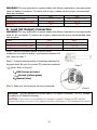
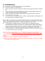
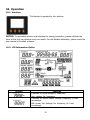
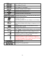
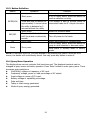
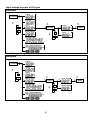
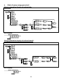
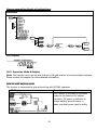
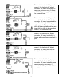
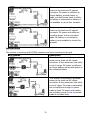
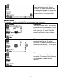
User Manual Hybrid PV Inverter Table Of Contents 1. 2. 3. Introduction ........................................................................................1 Important Safety Warning ..................................................................2 Unpacking & Overview ........................................................................4 3-1. Packing List ........................................................................................ 4 3-2. Product Overview ............................................................................... 4 4. Installation ..........................................................................................5 4-1. Selecting Mounting Location ................................................................ 5 4-2. Mounting Unit..................................................................................... 5 5. Grid (Utility) Connection ........................................................................7 5-1. Preparation ........................................................................................ 7 5-2. Connecting to the AC Utility ................................................................. 7 6. PV Module (DC) Connection ................................................................8 7. Battery Connection ..............................................................................9 8. Load (AC Output) Connection .......................................................... 10 9. Commissioning ................................................................................. 11 10. Operation.......................................................................................... 12 10-1. Interface ........................................................................................ 12 10-2. LCD Information Define................................................................... 12 10-3. Button Definition ............................................................................ 14 10-4 Query Menu Operation ..................................................................... 14 11. Charging Management ..................................................................... 24 12. Maintenance & Cleaning ................................................................... 26 13. Trouble Shooting ............................................................................... 27 13-1. Warning List ................................................................................... 27 13-2. Fault Reference Codes ..................................................................... 28 14. Specifications .................................................................................... 32 1. Introduction This hybrid PV inverter can provide power to connected loads by utilizing PV power, utility power and battery power. When PV energy output is good, it will power connected loads from solar electric (photovoltaic or PV) power, feed power back to grid (utility), and charge battery. When PV energy output is not sufficient for connected loads, this inverter will convert the utility at the same time. Hybrid inverter Distribution Box PV module Battery Figure 1 Electric grids Load Basic hybrid PV System Overview Depending on different power situations, this hybrid inverter is designed to generate continuous power from PV solar modules (solar panels), battery, and the utility. When MPP input voltage of PV modules is within acceptable range (see specification for the details), this inverter is able to generate power to feed the grid (utility) and charge battery. This inverter is only compatible with PV module types of single crystalline and poly crystalline. Do not connect any PV array types other than these two types of PV modules to the inverter. See Figure 1 for a simple diagram of a typical solar system with this hybrid inverter. Note: When PV input voltage is lower than 250V for 3KW and 150V for 2KW, the power of inverter will de-rate. 1 2. Important Safety Warning Before using the inverter, please read all instructions and cautionary markings on the unit and this manual. Store the manual where it can be accessed easily. This manual is for qualified personnel. The tasks described in this manual may be performed by qualified personnel only. General PrecautionConventions used: WARNING! Warnings identify conditions or practices that could result in personal injury; CAUTION! Caution identify conditions or practices that could result in damaged to the unit or other equipment connected. WARNING! Before installing and using this inverter, read all instructions and cautionary markings on the inverter and all appropriate sections of this guide. WARNING! Normally grounded conductors may be ungrounded and energized when a ground fault is indicated. WARNING! This inverter is heavy. It should be lifted by at least two persons. CAUTION! Authorized service personnel should reduce the risk of electrical shock by disconnecting AC, DC and battery power from the inverter before attempting any maintenance or cleaning or working on any circuits connected to the inverter. Turning off controls will not reduce this risk. Internal capacitors can remain charged for 5 minutes after disconnecting all sources of power. CAUTION! Do not disassemble this inverter yourself. It contains no user-serviceable parts. Attempt to service this inverter yourself may cause a risk of electrical shock or fire and will void the warranty from the manufacturer. CAUTION! To avoid a risk of fire and electric shock, make sure that existing wiring is in good condition and that the wire is not undersized. Do not operate the Inverter with damaged or substandard wiring. CAUTION! Under high temperature environment, the cover of this inverter could be hot enough to cause skin burns if accidentally touched. Ensure that this inverter is away from normal traffic areas. 2 CAUTION! Use only recommended accessories from installer . Otherwise, not-qualified tools may cause a risk of fire, electric shock, or injury to persons. CAUTION! To reduce risk of fire hazard, do not cover or obstruct the cooling fan. CAUTION! Do not operate the Inverter if it has received a sharp blow, been dropped, or otherwise damaged in any way. If the Inverter is damaged, called for an RMA (Return Material Authorization). 3 3. Unpacking & Overview 3-1. Packing List Before installation, please inspect the unit. Be sure that nothing inside the package is damaged. You should have received the following items inside of package: Inverter unit Software CD Manual USB cable 3-2. Product Overview 1) 2) 3) 4) 5) 6) 7) 8) 9) PV connectors Grid connectors Battery connectors AC output connectors (Load connection) RS-232 communication port USB communication port Intelligent slot LCD display panel (Please check section 10 for detailed LCD operation) Operation buttons 4 4. Installation 4-1. Selecting Mounting Location Consider the following points before selecting where to install: Do not mount the inverter on flammable construction materials. Mount on a solid surface This inverter can make noises during operation which may be perceived as a nuisance in a living area. Install this inverter at eye level in order to allow the LCD display to be read at all times. For proper air circulation to dissipate heat, allow a clearance of approx. 20 cm to the side and approx. 50 cm above and below the unit. Dusty conditions on the unit may impair the performance of this inverter. The ambient temperature should be between 0°C and 40°C to ensure optimal operation. The recommended installation position is to be adhered to (vertical). For proper operation of this inverter, please use appropriate cables for grid connection. Select an appropriate mounting location. Install the solar inverter in a protected area that is free of excessive dust and has adequate air flow. Do NOT operate it where the temperature and humidity is beyond the specific limits. (Please check the specs for the limitations.) This inverter is designed with IP20 for indoor applications only. 4-2. Mounting Unit WARNING!! Remember that this inverter is heavy! Please be carefully when lifting out from the package. Installation to the wall should be implemented with the proper screws. Mount the wall bracket so that the solar inverter can be easily attached to the wall. After that, the device should be bolted on securely. 5 1. Drill four holes in the marked locations with four screws. 2. 3. Check if the solar inverter is firmly secured. Place the unit on the surface and align the mounting holes with the four screws. Note: Recommended specs for screws. 6 5. Grid (Utility) Connection 5-1. Preparation Before connecting to AC utility, please install a separate AC circuit breaker between inverter and AC utility. This will ensure the inverter can be securely disconnected during maintenance and fully protected from over current of AC input. NOTE1: Although this inverter is equipped with a fuse (F6 point on PCB, 250VAC/30A for 3KW; F6 and F7 points on PCB, 250VAC/30A for 2KW), it’s still necessary to install a separate circuit breaker for safety consideration. Please use 250VAC/30A circuit breaker. WARNING! It's very important for system safety and efficient operation to use appropriate cable for grid (utility) connection. To reduce risk of injury, please use the proper recommended cable size as below. Suggested cable requirement for AC wire Model 2KW 3KW Nominal Grid Voltage 101/110/120/127 VAC 208/220/230/240 VAC Conductor cross-section (mm2) ≥4.17 ≥3.35 AWG no. 10 - 11 10 - 12 5-2. Connecting to the AC Utility Step 1: Check the grid voltage and frequency with an AC voltmeter. It should be the same to “VAC” value on the product label. Step 2: Turn off the circuit breaker. Step 3: Remove insulation sleeve 8 mm for three conductors. And shorten phase L and neutral conductor N 3 mm. Refer to chart 1. Chart 1 Step 4: Connect wires according to polarities indicated on terminal block. Be sure to connect PE protective conductor ( ) first. L→LINE (brown or black) →Ground (yellow-green) N→Neutral (blue) Chart Step 5: Make sure the wires are securely connected. 2 CAUTION: To prevent risk of electric shock, ensure the ground wire is properly earthed before operating this hybrid inverter no matter the grid is connected or not. 7 6. PV Module (DC) Connection CAUTION: Before connecting to PV modules, please install separately a DC circuit breaker between inverter and PV modules. NOTE: Please use 600VDC/25A circuit breaker for 3KW; 500VDC/25A for 2KW.. Please follow below steps to implement PV module connection: WARNING: This inverter is only compatible to two types of PV modules: single crystalline and poly crystalline. To avoid any malfunction, do not connect any PV modules with possibility of leakage current to the inverter. Step 1: Check the input voltage of PV array modules. The acceptable input voltage of the solar inverter is 250VDC - 450VDC for 3KW and 150VDC-320VDC for 2KW. This system is only applied with one string of PV array. Please make sure that the maximum current load of PV input connector is 13A for 3KW and 15A for 2KW.. CAUTION: Exceeding the maximum input voltage can destroy the unit!! Check the system before wire connection. Step 2: Disconnect the circuit breaker. Step 3: Remove insulation sleeve 10 mm for positive and negative conductors. Refer to chart 3. Step 4: Check correct polarity of connection cable from PV modules and PV input connectors. Then, connect positive pole (+) of connection cable to positive pole (+) of PV input connector. Connect negative pole (-) of connection cable to negative pole (-) of PV input connector. Refer to Chart 4. Chart 3 Step 5: Make sure the wires are securely connected. 8 Chart 4 WARNING! It's very important for system safety and efficient operation to use appropriate cable for PV module connection. To reduce risk of injury, please use the proper recommended cable size as below. Conductor cross-section (mm2) ≥3.35 AWG no. 6 - 12 CAUTION: Never directly touch terminals of the inverter. It will cause lethal electric shock. CAUTION: If it’s necessary to turn off the inverter during operation, make sure to disconnect the AC breaker first and then PV DC breaker. 7. Battery Connection CAUTION: Before connecting to batteries, please install separately a DC circuit breaker between inverter and batteries. NOTE: Please only use sealed lead acid battery, vented and Gel battery. Please check maximum charging voltage and current when first using this inverter. If using Lithium iron or Nicd battery, please consult with installer for the details. NOTE: Please use Please use 60VDC/100A circuit breaker for 3KW and 60VDC/80A circuit breaker for 2KW. Please follow below steps to implement battery connection: Step 1: Check the nominal voltage of batteries. The nominal input voltage for hybrid inverter is 48VDC. Step 2: Use two battery cables. Remove insulation sleeve 12 mm and insert conductor into cable ring terminal. Refer to chart 5. Step 3: Following battery polarity guide printed near the battery terminal! Place the external battery cable ring terminal over the battery terminal. Refer to Chart 6. RED cable to the positive terminal (+); BLACK cable to the negative terminal (-). Chart 5 Step 4: Make sure the wires are securely connected Chart 6 9 WARNING! It's very important for system safety and efficient operation to use appropriate cable for battery connection. To reduce risk of injury, please use the proper recommended cable size as below. Model 2KW 3KW Nominal Grid Voltage 101/110/120/127 VAC 208/220/230/240 VAC Conductor cross-section (mm2) ≥8.37 ≥13.3 AWG no. ≤8 ≤6 8. Load (AC Output) Connection WARNING! It's very important for system safety and efficient operation to use appropriate cable for AC connection. To reduce risk of injury, please use the proper recommended cable size as below. Model 2KW 3KW Nominal Grid Voltage 101/110/120/127 VAC 208/220/230/240 VAC Conductor cross-section (mm2) ≥4.17 ≥3.35 AWG no. 10 - 11 10 - 12 Step 1: Remove insulation sleeve 8 mm for three conductors. And shorten phase L and neutral conductor N 3 mm. Refer to chart 7. Step 2: Connect wires according to polarities indicated on terminal block. Be sure to connect PE protective conductor ( ) first. Refer to Chart 8. Chart 7 L→LINE (brown or black) →Ground (yellow-green) N→Neutral (blue) Step 3: Make sure the wires are securely connected. Chart 8 CAUTION: It’s only allowed to connect load to “AC Output Connector”. Do NOT connect the utility to AC Output Connector. CAUTION: This inverter is not allowed to operate in parallel. Please do NOT parallel connect more than one unit in AC output connector. Otherwise, it will damage this inverter. 10 9. Commissioning Step 1: Check the following requirements before commissioning: Ensure the inverter is firmly secured Check if the open circuit DC voltage of PV module meets requirement (Refer to Section 6) Check if the open circuit utility voltage of the utility is at approximately same to the nominal expected value from local utility company. Check if connection of AC cable to grid (utility) is correct if the utility is required. Full connection to PV modules. AC circuit breaker (only applied when the utility is required), batter circuit breaker, and DC circuit breaker are installed correctly. Step 2: Switch on the battery circuit breaker and then switch on PV DC breaker. After that, if there is utility connection, please switch on the AC circuit breaker. At this moment, the inverter is turned on already. However, there is no output generation for loads. Then: If LCD lights up to display the current inverter status, commissioning has been successfully. After pressing “ON” button for 1 second when the utility is detected, this inverter will start to supply power to the loads. If no utility exists, simply press “ON” button for 3 seconds. Then, this inverter will start to supply power to the loads. If red LED lights up, or warning/fault indicator appears in LCD, an error has occurred to this inverter. Please inform your installer. Step 3: Install monitoring software in your PC. Follow below steps to install software. 1. Go to the website http://www.power-software-download.com/solarpower.html to download software in your PC. Then, please execute setup.exe for initiating installation software. 2. Follow the on-screen instructions to install the software. 3. When your computer restarts, the monitoring software will appear as shortcut icon located in the system tray, near the clock. 11 10. Operation 10-1. Interface This display is operated by four buttons. NOTICE: To accurately monitor and calculate the energy generation, please calibrate the timer of this unit via software every one month. For the detailed calibration, please check the user manual of bundled software. 10-2. LCD Information Define Display Function Indicates AC input voltage or frequency. Vac: voltage, Hz: frequency Indicates AC output power, voltage, frequency, or load percentage. KW: power, Vac: Voltage, Hz: frequency, %: Load percentage 12 Indicates PV input voltage or power. Volt: voltage, KW: power Indicates battery voltage or percentage. Volt: voltage, %: percentage Indicates charging current to battery. Indicates that the warning occurs. Indicates that the fault occurs. Indicates fault code or warning code. Indicates date and time, or the date and time users set for querying energy generation. Indicates solar panels. Icon flashing indicates PV input voltage or is out of range. Indicates utility. Icon flashing indicates utility voltage or frequency is out of range. Indicates battery condition. And the lattice of the icon indicates battery capacity. Icon Icon flashing indicates battery is not connected. flashing indicates the battery voltage is too low. Indicates AC output for loads is enabled and inverter is providing power to the connected loads. Indicates AC output for loads is enabled but there is no power provided from inverter. At this time, no battery and the utility are available. Only PV power exists but is not able to provide power to the connected loads. Indicates overload. Indicates PV energy generated. 13 10-3. Button Definition Button Operation Short press. ENTER/ON ESC/OFF Up Press and hold the button for approximately 1 second when the utility is detected or 3 seconds without the utility. Short press. Press and hold the button until the buzzer continuously sounds. Short press. Function Enter query menu. If it’s in query menu, press this button to confirm selection or entry. This inverter is able to provide power to connected loads via AC output connector. Return to previous menu. Turn off power to the loads. Select last selection or increase value. If it’s in query menu, press this button to jump to next selection or decrease value. Down Short press. Mute alarm in standby mode or battery mode. NOTE: If backlight shuts off, you may activate it by pressing any button. When an error occurs, the buzzer will continuously sound. You may press any button to mute it. 10-4 Query Menu Operation The display shows current contents that have been set. The displayed contents can be changed in query menu via button operation. Press ‘Enter’ button to enter query menu. There are seven query selections: Grid(Utility) voltage or frequency of AC input Frequency, voltage, power or load percentage of AC output Input voltage or power of PV input. Battery voltage or capability percentage. Date and time. Today or total energy generated. Mode of query energy generated. 14 Setting Display Procedure Input voltage or frequency of AC input Procedure 1. Enter 3. Enter 2. 4. 5. Enter Up Down Up Down Frequency, voltage, power or percentage of AC output Procedure 1. Enter 3. Enter 2. Up 4. Down 15 5. Enter Up Down Input voltage or power of PV input. Procedure 1. Enter 2. Up 3. Enter 5. Enter Down 4. Up Down Battery voltage or percentage. Procedure 1. Enter 2. Up Down 3. Enter 4. 16 5. Enter Up Down Date and time. Procedure 1. Enter 2. Up Down 3. Enter 4. 5. Enter Up Down Today or total energy generated. Procedure Enter Up Down 3. Enter 4. 17 Enter Up Down Mode of query energy generated. Energy generation display of selected day Procedure 1. Enter 2. Up Down Enter Up Down Enter Up Down Flashes 3. Enter 4. Up Down Sets month Flashes Up 6. Sets year Esc 5. Enter Down Enter Enter Up Down Returns to main menu Sets day Flashes LCD Display: Energy generation display of selected month Procedure 1. Enter 2. Up Down 3. Enter 4. Enter Flashes Up Down 5. Enter Up 6. Down LCD Display: 18 Enter Flashes Up Down Sets year Up Down Sets month Esc Enter Returns to main menu Energy generation display of selected year Procedure 1. Enter 2. Up Down 3. Enter 4. Up Esc Down 5. Enter Enter Flashes Up Down Sets year Enter Returns to main menu LCD Display: 10-5. Operation Mode & Display Note: This inverter can be set up as a Grid-tie or Off-grid inverter by communication interface. Please contact the supplier for more detailed information. Grid-tie with backup mode This inverter is connected to grid and working with DC/INV operation. LCD Display Description This inverter is activated to generate power to the loads via AC output connector. PV power is sufficient to charge battery, provide power to loads, and feed power back to utility. 19 This inverter is activated to generate power to the loads via AC output connector. PV power is charging the battery. At the same time, PV power and the utility are supplying power to the connected load. This inverter is activated to generate power to the loads via AC output connector. PV power is generated, but not sufficient enough to charge battery by itself. PV power and the utility are charging battery at the same time. And the utility is also supplying power to the connected load. This inverter is disabled to generate power to the loads via AC output connector. PV power is sufficient to charge battery and feed power back to grid. This inverter is disabled to generate power to the loads via AC output connector. PV power and utility are charging battery at the same time. This inverter is disabled to generate power to the loads via AC output connector. PV power is feeding power back to the utility. No battery is connected or battery is not available to use at this moment. 20 This inverter is activated to generate power to the loads via AC output connector. PV power is sufficient to charge battery, provide power to loads, and feed power back to utility. No battery is connected or battery is not available to use at this moment. This inverter is activated to generate power to the loads via AC output connector. PV power and utility are providing power to the connected loads. No battery is connected or battery is not available to use at this moment. Inverter mode This inverter is working with DC/INV operation and not connecting to the grid. LCD Display Description This inverter is activated to generate power to the loads via AC output connector. At the same time, the utility is out of range. PV power is sufficient to charge battery and provide power to the connected loads. This inverter is activated to generate power to the loads via AC output connector. At the same time, the utility is out of range. PV power is generated, but not sufficient enough to power loads by itself. PV power and battery are providing power to the connected loads at the same time. 21 This inverter is activated to generate power to the loads via AC output connector. At the same time, the utility is out of range. PV power is not detected or available at this moment. Only battery power is available to provide power to connected loads. This inverter is activated to generate power to the loads via AC output connector. At the same time, the utility is out of range. No battery is connected or battery is not available to use at this moment. Only PV power is available to provide power to connected loads. Bypass mode The inverter is working without DC/INV operation and connecting to the loads. LCD Display Description This inverter is activated to generate power to the loads via AC output connector. At the same time, PV power is not detected or available. Only utility is charging battery and providing power to connected loads. Inverter fault occurs. But this inverter is activated to generate power to the loads via AC output connector. PV power is charging battery and the utility is providing power to the connected loads. Note: Refer to section 10-2 for detailed fault reference. 22 This inverter is activated to generate power to the loads via AC output connector. PV power and battery are not detected or available to use at this moment. Only utility is available to provide power to connected loads. Standby mode : The inverter is working without DC/INV operation and load connected. LCD Display Description The utility is out of range. This inverter is disabled on AC power output or even AC power output is enabled, but an error occurs on AC output. Only PV power is sufficient to charge battery. This inverter is disabled to generate power to the loads via AC output connector. PV power is not detected or available at this moment. Only utility is available to charge battery. This inverter is disabled to generate power to the loads via AC output connector. PV power and the utility are not detected or available at this moment. 23 11. Charging Management Default Value Charging voltage Max. charging current It can be adjusted via software from 5Amp to 25Amp. 25A Floating charging voltage(default) 54.0 Vdc Max. absorption charging voltage(default) 56.0 Vdc Battery overcharge protection 59.0 Vdc Charging process based on default Note It can be adjusted via software from 50Vac to 56Vdc. = Floating charging voltage + 2Vdc. But the max. absorption charging voltage is 57Vdc. Therefore, if floating charging voltage is set to 56Vdc, then max. absorption charge voltage will be still 57Vdc. U setting. Bulk Voltage Float Voltage 3 stages: First – max. charging voltage Bulk Absorption Floating time increases to 56V; I Second- charging voltage will maintain at 56V until charging current is down to 5 Amp; time Third- go to floating charging at 54V. This inverter can connect to battery types of Sealed lead acid battery, Vented battery and Gel battery. Below is recommended floating charging voltage table based on different battery types. Battery type Sealed lead acid battery Vented battery Gel battery Recommended floating charging voltage 53.6 V 52.8 V 54.0 V 24 If using sealed lead acid battery, please set up the floating charging current according to below formula: The maximum floating charging current = Battery capacity (Ah) x 0.2 For example, if you are using 125 Ah battery, then, floating charging current is 125 x 0.2=25 (A). Please use at least 25Ah battery because the settable minimum value of maximum charging current is 5Ah. If using gel or vented battery, please consult with installer for the details. Below is setting screen from software: 25 12. Maintenance & Cleaning Check the following points to ensure proper operation of whole solar system at regular intervals. Ensure all connectors of this inverter are cleaned all the time. Before cleaning this inverter, be sure to turn off all the breakers (AC breaker, battery breaker and PV DC breaker). Clean this inverter, during the cool time of the day, whenever it is visibly dirty. Periodically inspect the system to make sure that all wires and supports are securely fastened in place. WARNING: There are no user-replaceable parts inside of the inverter. Do not attempt to service the unit yourself. 26 13. Trouble Shooting When there is no information displayed in the LCD, please check if PV module connection is correctly connected. 13-1. Warning List There are 21 situations defined as warnings. When a warning situation occurs, icon will flash and the fault code area will display “WR” wordings. You may check software for the detailed warning situations. Please contact your installer when below warning situations occur. Warning CPU is performing the auto-correction of AD signals. Data saving failure. Input PV is found lost. PV input voltage reads low. Power island An Error occurred in the CPU initialization Power grid voltage exceeds the upper threshold Power grid voltage falls below the lower threshold Power grid frequency exceeds the upper threshold Power grid frequency falls below the lower threshold Power grid-connected average voltage exceeds the maximum threshold Emergent grid disconnection Battery voltage is too low. Low battery Battery is disconnected. End of battery discharge. Overload Over temperature alarm Icon (flashing) Description Sampling adjustment is in process in DSP. Flash memory fails. The PV input voltage is out of range. The input PV voltage is too low to initiate the inverter. Islanding condition is detected. Initialization failed in CPU when the inverter is turned on. The grid voltage has exceeded the highest limit. The grid voltage is beyond the lowest limit. The grid frequency has exceeded the highest limit. The grid frequency is beyond the lowest limit. Average feeding voltage has exceed the upper limit The utility is abnormal. The battery voltage is less than 42V. Battery voltage is less than 25% of battery capacity or the battery voltage less than 44V. Battery is not detected. Low voltage from over discharging. Battery voltage is below 42V. This battery is charging now and not achieving to 50V yet. Overload Over temperature 27 Warning Icon Description (flashing) No electrical ground Ground loss 13-2. Fault Reference Codes When a fault occurs, the icon will flash as a reminder. See below for fault codes for reference. Situation Solution Fault Icon Fault Event Code (flashing) 01 DC bus voltage exceeds the 1. Disconnect AC circuit upper threshold breaker first. Then, disconnect DC circuit 02 DC bus voltage falls below breaker. the lower threshold 2. Until LCD screen 03 DC bust voltage soft-start is completely shuts down, time-out turn on DC breaker first. It 04 Inverter soft-start is will show “No Utility” in time-out LCD screen. Then, turn on 05 An Inverter overcurrent AC breaker. After 300 event is detected seconds, the system will 07 An relay failure event is automatically connect to detected the grid. 08 DC component in the output 3. If the error message still current exceeds the upper remains, please contact threshold your installer. 11 Over-current on PV input is detected 14 Inverter DC component exceeds the allowable range 16 Leakage current CT failed 06 Over temperature fault 1. The internal temperature is higher than specified temperature. 2. Leave inverter to be cooled to room temperature. 3. If the error message still remains, please contact your installer. 28 Situation Fault Code 09 Fault Event Solution Icon (flashing) PV input voltage exceeds the upper threshold 1. 2. 10 Auxiliary power* failed 1. 2. 3. *Auxiliary power means switch power supply. 12 Leakage current exceeds the allowable range 1. 2. 3. 4. 29 Check if the open circuit voltage of PV modules is higher than 500VDC. If PV open circuit voltage is less than 500VDC and the error message remains, pelase contact your installer. Turn off the inverter. Then, restart the inverter. If the error message still remains, please contact your installer. The ground voltage is too high. Please disconnect AC breaker first and then DC breaker. Check if grounding is connected properly after LCD screen completely shuts down. If grounding is correctly connected, turn on DC brearker. After it displays “No Utility” in LCD screen, turn on AC breaker. After 300 seconds, the system will automatically connect to the grid. If the error message still remains, please contact your installer. Situation Fault Code 13 Fault Event Solution Icon (flashing) PV insulation resistance is too low 1. 2. 15 17 20 21 A difference occurred in the readings from the main and secondary controllers Communication with the main and secondary controllers is interrupted Discharge circuit fault Soft start in battery discharge fails 1. 2. 3. 22 Charging voltage is too high 1. 2. 3. 4. 23 Overload fault 1. 2. 30 Check if the impedance between positive and negative poles to the ground is greater than 1MΩ. If the impedance is lower than 1MΩ, please contact your installer. Please disconnect AC breaker first and then disconnect DC breaker. After LCD screen is completely off, turn on DC breaker. Until it shows “No Utility” in LCD display, turn on AC breaker. After 300 seconds, the system will automatically connect to the grid. If error message remains, please contact your installer. Check if the connection between battery and inverter is well. Make sure battery condition is ok. Then, restart the inverter. If error message remains, please contact your installer. Remove exessive loads. Be sure that total connected loads are less than maximum power consumption this inverter can support. Then, restart the inverter. Situation Fault Code 24 Fault Event Solution Icon (flashing) Battery disconnected 1. 2. 25 26 Inverter current is too high for a long time Short circuited on inverter output 1. 2. 1. 2. 3. 4. 5. 27 Fan fault 1. 2. 3. 31 Check if battery cable is connected firmly. If error message remains, please contact your installer. Remove exessive loads. Then, restart the inverter. Turn off the inverter. Disconnect AC circuit breaker first. Then, disconnect DC circuit breaker and then disconnect the loads. Please check if load circuit is ok. After removing the error, turn on the PV DC breaker and battery breaker. Turn on the inverter. If error message remains, please contact your installer. Please check if fans are runing ok. If fans are runing ok, please shut down inverter first and then, restart it. If fans are stop runing or error message remains after restart the inverter, please contact your installer. 14. Specifications MODEL Hybrid Inverter 2KW Hybrid Inverter 3KW RATED POWER 2000 W 3000 W PV INPUT (DC) Nominal DC Voltage 300 VDC 360 VDC Maximum DC Voltage 350 VDC 500 VDC Start-up Voltage / Initial Feeding Voltage 80 VDC / 120 VDC 116 VDC / 150 VDC MPP Voltage Range 150 VDC ~ 320 VDC 250 VDC ~ 450 VDC Maximum Input Current 15 A 13 A GRID/UTILITY OUTPUT (AC) Nominal Output Voltage 101/110/120/127 VAC 208/220/230/240 VAC Output Voltage Range 88 - 127 VAC 184 - 265 VAC 47.5 ~ 51.5 Hz or 47.5 ~ 50.2 Hz or Output Frequency Range 57.5 ~ 61.5 Hz 59.3~ 60.5Hz Nominal Output Current 18 A 13.6 A Power Factor > 0.99 AC INPUT AC Start-up Voltage 60-70 VAC 120-140 VAC Auto Restart Voltage 90 VAC 194 VAC Acceptable Input Voltage Range 80 - 130 VAC 184 - 265 VAC Maximum AC Input Current 30 A 20 A BATTERY MODE OUTPUT (AC) Nominal Output Voltage 101/110/120/127 VAC 208/220/230/240 VAC Output Frequency 50 Hz / 60 Hz (auto sensing) Output Waveform Pure sine wave Efficiency (DC to AC) 90% 92% BATTERY & CHARGER Nominal DC Voltage 48 VDC Maximum Charging Current 25 A GENERAL PHYSICAL Dimension, D X W X H (mm) 480 x 438 x 117 Net Weight (kgs) 15.57 INTERACE Communication Port RS-232/USB Optional SNMP, Modbus and AS-400 cards Intelligent Slot available ENVIRONMENT Humidity 0 ~ 90% RH (No condensing) Operating Temperature 0 to 40°C Altitude 0 ~ 1000 m* *Power derating 1% every 100 m when altitude is over 1000m. 32