1
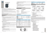
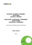
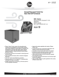
2
1
Environment Parameters
H2U Series PLC User Manual
Code: 19010136 V0.0
Main features of the H2U series PLC:
☞☞Built-in large program memory space without an external extension memory
card can reach up to 24K steps.
☞☞An internal large-capacity power supply can directly provide power to externally
connected devices such as sensors, HMI, and external auxiliary relays.
☞☞It provides high-speed, multi-channel and high-frequency I/O terminals, and has
rich operation and positioning control functions.
☞☞It integrates four independent communication ports, which support multiple
communication protocols including MODBUS instruction and are convenient for
system integration.
☞☞It provides comprehensive encryption function that can protect users’ intellectual
property rights.
☞☞It supports up to 128 subprograms and 21 interrupt subprograms.
☞☞It comes with fast execution speed.
Safety Precautions
Before operating the equipment, please read the safety precautions carefully so as to
ensure your safety and prevent damage to property. Installation and operation of the
product may only be performed by the authorized personnel who have been strictly
trained, comply with the precautions in the manual, and observe related industry
safety code.
Design Precautions
Provide a safety circuit outside the PLC so that the application system can still work
safely once external power failure or PLC fault occurs. Take the following aspects into
considerations in design:
☞☞Outside the PLC, an emergency stop circuit, a protection circuit, an interlock
circuit and a positioning limit circuit may be necessary to prevent damage to
your machine.
☞☞To ensure safe operation of the machine, please design external protection
circuit and safety mechanism for the output signals that may cause heavy
accidents.
☞☞When the PLC CPU detects its own system abnormality, all outputs may be
closed. When part of the controller circuit fails, related outputs may be out of
control. Thus, design an appropriate external circuit to ensure normal operation
of the machine.
☞☞If output units (relay or transistor) are damaged, related outputs may be kept on
the “ON” or “OFF” status.
☞☞PLC is designed for indoor electric environment. Its power supplies should have
lightning protection device. Ensure that lightening over-voltage is not applied on
PLC terminals so as to avoid damage to the machine.
Installation Precautions
Type
☞☞Don’t supply external power to terminal 24+ of the main unit or expansion
units. Do not wire vacant terminals externally.
☞☞Select shielded cables as high-frequency signal input/output cables in applications
with serious interference so as to enhance system anti-interference ability.
☞☞Please use wires of above 2mm² to connect the ground terminal of the main unit to
avoid sharing grounding with the heavy electrical system.
Startup and Maintenance Precautions
☞☞Do not touch any terminal while power is on. Otherwise, electric shock or
malfunction may be caused.
☞☞Make sure power supplies are cut off before cleaning or retightening terminal.
Otherwise, you may be shocked by electricity.
☞☞Please connect or remove the communication cable and the cables of expansion
modules and control unit after cutting off all power supplies. Otherwise, machine
damage or malfunctions may be caused.
☞☞Perform operations such as online modification, coercible output, RUN and STOP
after understanding the instruction manual and ensuring the safety of the machine.
☞☞When inserting or removing remote extension card, make sure that power supplies
are cut off.
☞☞Make sure to replace coin battery at power-off. If you really need to replace
the battery during power supply, let professional electrical technician wearing
insulating gloves complete replacement within 30 seconds. Otherwise, data loss
may result.
☞☞Please dispose scrapped PLC as industrial wastes.
Product Information
1
① Product Information
② Series No.
③ Total Inputs
④ Total Outputs
⑤ Module Classification
2
3
4
5
6
7
8
9
Dipping
H2U-1616MR-XP
H2U-1616MT-XP
32
16
H2U-2416MR-XP
40
24
6×60kHz
Input
VOLT
6×100kHz DC24V
2×60kHz
4×10kHz
2×100kHz
4×10kHz DC24V
H2U-2416MTQ-F01
6×100kHz
6×100kHz
H2U-3624MR-XP
2×60kHz
4×10kHz
2×100kHz
DC24V
4×10kHz
H2U-3624MT-XP
60
36
H2U-3232MR-XP
H2U-3232MT-XP
H2U-3232MTQ
64
32
6×60kHz
6×100kHz
6×100kHz
6×100kHz
/
/
H2U-3232MTP
H2U-4040MR-XP
H2U-4040MT-XP
H2U-6464MR-XP
H2U-6464MT-XP
80
128
40
64
6×60 kHz
16
16
DC24V
6×100kHz DC24V
24
32
40
64
Relay
3×100kHz
Transistor
/
Relay
/
Relay
2×100kHz
Transistor
/
Relay
3×100kHz
Transistor
5×100kHz
Transistor
8×100kHz
Transistor
/
Relay
3×100kHz
Transistor
/
Relay
3×100kHz
Transistor
1.3 General Specifications
Type
Climatic Condition
Ambient
Temp.
Humidity
Air
Pressure
3.5 (5-9Hz)
/
/
m/s2
10 (9-150Hz)
/
/
/
5-20Hz: 1.92dB
20-200Hz: -3dB
/
/
5-200
/
/
X/Y/Z
/
/
Half-sine
/
Acceleration
m2/s3(dB/Oct)
Spectral Density
Frequency
Hz
Range
Vibration
/
Direction
Type
/
Acceleration
m/s2
/
180
/
Dipping Height
m
/
1
/
I/O control mode
Programming language
Max. storage capacity
Basic sequence
Control/ step-ladder
Instruction
diagram
type
Application
Instruction
Execution
Speed
Counter
(C)
Transistor
Note:
Total inputs include hi-speed inputs. Hi-speed input terminals can be used for common
inputs. Total frequencies of H2U-XP hi-speed inputs cannot exceed 70kHz. Total
frequencies of H2U hi-speed inputs cannot exceed 100kHz.
Storage
Ambient
Condition
Parameter
Unit
Ambient
Condition
Transport
Ambient
Condition
Low Temp.
℃
-5
-40
-40
High Temp.
Relative
Humidity
Low Pressure
℃
55
70
70
%
95 (30℃±2℃)
95 (40℃±2℃)
/
kPa
70
70
70
High Pressure
kPa
106
106
106
Environment Parameters
mm
Acceleration
Basic Instruction
Application
Instruction
Total inputs when
extended
Total outputs when
extended
Total I/Os when
extended
General
※1
Data
register
(32-bit
when a
pair is
used)
Pointer
Nesting
Pointer
Constants
128 kinds
298 instructions
0.26μs/ instruction (H2U-XP: 0.1μs/
instruction)
1 to hundreds of μs/ instruction (H2U-XP: 0.5
to hundreds of μs/ instruction)
X000-X377
256 points
(Octal No.)
Y000-Y377
256 points
(Octal No.)
Octal No.
256 points
M0-M499
500 points
M500-M1023
524 points
Latched
※3
M1024-M3071
2,048 points
Special
M8000-M8255
256 points
Initialization
S0-S9
10 points
General
※1
S10-S499
490 points
Latched
※2
S500-S899
400 points
S900-S999
100 points
200 points
(0.1-3276.7seconds)
46 points
(0.01-327.67seconds)
4 points (0.001-32.767
seconds)
6 points (0.1-3276.7
seconds)
100 points (0-32767
counting)
100 points
(0-32767counting)
20 points
(-2147483648 to
+2147483647counting)
15 points
(-2147483648 to
+2147483647counting)
21 points (-2147483648
to +2147483647
counting)
200 points
100ms
T0-T199
10ms
T200-T245
Cumulative 1ms ※3
T246-T249
Cumulative 100ms
※3
16-bit unidirectional
※1
16-bit unidirectional
※2
T250-T255
32-bit bi-directional
※1
C200-C219
C0-C99
C100-C199
32-bit bi-directional
※2
C220-C234
32-bit hi-speed bidirectional ※2
C235-C255
16-bit general
D0-D199
※1
16-bit latched ※2
D200-D511
16-bit latched ※3
D512-D7999
16-bit special
For use with index
address 16 bit
For branch use with
JAMP.CALL
Input interrupt
D8000-D8255
312 points
7488 points
(Take 500 points as the
unit to set file registers
after D1000)
256 points
V0-V7, Z0-Z7
16 points
P0-P127
128 points
I00□-I50□
6 points
Timer interrupt
I6□□-I8□□
3 points
Counter interrupt
I010-I060
6 points
Master control
N0-N7
8 points
Decimal (K)
16-bit:-32768 to
+32767
16-bit: 0-FFFF
32-bit: -2147483648 to
+2147483647
32-bit: 0-FFFFFFFF
Hexadecimal (H)
Mounting Dimension
Figure 1 Mounting dimension diagram
D
W
A
B
H
Mounting hole 05×4
27 sequential control instructions, 2 stepladder diagram instructions
※2
※2
Mechanical Design
Table 1 Physical dimension
Latched
Signal
/
2×100kHz
Displacement
Circular scanning and interrupting instruction
Batch processing mode (when END
instruction is executed, I/Os immediately
refresh.)
Ladder diagram (LD), instruction list (IL) and
sequential function chart (SFC)
24K steps including file registers
Hi-speed
Output Type
O/Ps
5×100kHz
6×100kHz DC24V
6×60 kHz
Total
O/Ps
Storage
Ambient
Condition
Operation control mode
Timer (T)
Total
Hi-speed
Hi-speed
I/Os Total
I/Ps I/Ps (H2U-XP) I/Ps (H2U)
Transport
Ambient
Condition
H2U Series
I/O Features
Model
Ambient
Condition
Item
State
Register
(S)
Basic Parameters
Unit
Performance Specifications
Auxiliary
Relay (M)
H: Inovance controller
2U: the second generation controller
32: 32 inputs
32: 32 outputs
M: Main module of general purpose controller
P: Positioning controller
N: Network Controller
E: Extension Module
R: Relay
T: Transistor
⑥ Output Type
A: AC 220V (Null indicates AC220V by default)
⑦ Power Supply Type
B: AC110V C: AC24V D: DC24V
⑧ Special Function Identification
Such as high speed I/O function and analog function, etc.
⑨ Auxiliary version No. XP: 9
Wiring Precautions
☞☞Make sure all power supplies are cut off before the installation or wiring work.
☞☞Please connect AC power supply to the L/N terminal correctly.
☞☞When handling screw holes and wiring, do not make metal filings and wire lead
drop into controller vent holes. Otherwise, fire, failure, or malfunction may result.
☞☞Do not connect or plug/unplug the cable in the state of power supply. Otherwise,
electric shock or damage to circuit may result.
Shock
H2U-3232MRAX-XP
H2U-2416MT-XP
☞☞Do not install the PLC in the places where dust, oil smoke, conducting dust,
corrosive gas, or combustible gas exists; where it will be exposed to high
temperature, dew, wind and rain; and where vibration or shock occurs. In
addition, electric shock, fire, maloperation may also cause damage and
deterioration to the controller.
☞☞When handling screw holes and wiring, do not make metal filings and wire lead
drop into the controller vent holes. Otherwise, a fire, failure, and malfunction
may be caused.
☞☞Ensure there are no foreign bodies including packaging materials like dustproof
paper on the face of ventilation after installation is complete. Otherwise, poor
heat dispersion may be caused during running, which may lead to a fire, failure
and malfunction.
☞☞Do not connect or plug/unplug the cable in the state of power supply. Otherwise,
electric shock or damage to circuit may result.
☞☞The Installation and wiring should be fixed and reliable. Otherwise, poor contact
may cause malfunction.
☞☞Select shielded cables as hi-frequency signal input/output cables in applications
with serious interference so as to enhance system anti-interference ability.
Random
Vibration
Total I/Os
Designation Rules
Parameter
Sine
Vibration
Mechanical Stress
Thank you for purchasing the H2U Series Programmable Logic Controller developed
by Inovance Control Technology Co., Ltd. Before using the equipment, please read
this manual carefully to fully understand the features of the product so as to ensure
correct use.
This manual mainly describes the specifications, features and usage of the H2U series
PLC. For the developing environment and design of user programs, see the “AutoShop
Programming User Manual” and the “H1UH2U Series Programmable Logic Controller
Instruction & Programming Manual”, and the “H2U Series Communication Manual”
that are also issued by our company.
The manual is subject to change without a notice due to product upgrade, specification
modification as well as the efforts to increase the accuracy and convenience of the
manual.
4
3
Note:
※1: Non-battery backup area can be changed into battery backup area via parameter
setup.
※2: Battery backup area can be changed into non-battery backup area via parameter
setup.
※3: Such permanent battery backup area cannot be changed.
Model
Total
I/Os
H2U-1616M_
H2U-2416M_
Mounting Dimension
A (mm)
B (mm)
Dimension
W×H×D (mm)
32
160
80
170×90×88
40
160
80
170×90×88
H2U-3624M_
60
210
80
220×90×88
H2U-3232M_
64
210
80
220×90×88
H2U-4040M_
80
275
80
285×90×88
H2U-6464M_
128
340
80
350×90×88
Requirements on Mounting Position
☞☞Do not remove the paper tape that prevents foreign objects from dropping into
the unit during installation. Once installation is complete, remove the paper tape
before power-on so as to prevent overheating.
☞☞To prevent overheating inside the PLC, mount the unit in wall-hanging mode, as
shown in Figure 1. Keea a distance of 300mm at the top and bottom.
☞☞Leave a distance of 50mm or more between the main PLC module and other
devices or structures. Keep the equipment as far as possible away from the highvoltage cable, high-voltage devices and power devices.
How to Fix the PLC
The H2U Series PLC can be installed with the DIN rail or directly with four screws M4 in
a shock application.
To fix the PLC with the DIN rail, do as follows:
1) Fix the DIN rail on the backplane horizontally.
2) Pull out the DIN rail buckle at the bottom of the module.
3) Link the module onto the DIN rail, push the buckle back in position, and then lock the
module.
4) Finally fix the DIN-rail to two sides of the module so as to avoid sliding around.
Electrical Design
Here is the configuration of main module input and output terminal blocks of the H2U
Series PLC. Relay and transistor, output type of the PLC, share the same terminal
configuration.
Product Structure
1
2
3
4
11
12
13
14
15
16
485+ 485-485+ 485-
COM2 COM1
L
N
S/S
0V
24V
0V
X00
X02
X04
X06
X10
X12
X14
X16
X20
X22
X24
X26
X30
X32
X34
X36
24V
X01
X03
X05
X07
X11
X13
X15
X17
X21
X23
X25
X27
X31
X33
X35
X37
IN
L
N
S/S
0V
24V
0V
X00
X02
X04
X06
X10
X16
X20
X26
X30
X32
X34
X36
X12
X14
X22
X24
24V
X01
X03
X05
X07
X11
X13
X15
X17
X21
X23
X25
X27
X31
X33
X35
X37
+
BAT
00 01 02 03 04 05 06 07 20 21 22 23 24 25 26 27
-
10 11 12 13 14 15 16 17 30 31 32 33 34 35 36 37
IN
00 01 02 03 04 05 06 07 20 21 22 23 24 25 26 27
10 11 12 13 14 15 16 17 30 31 32 33 34 35 36 37
RUN
RUN
ERR
ERR
H 2U-3232MR-XP
OUT00 01 02 03 04 05 06 07
RELAY UNIT
OUT00 01 02 03 04 05 06 07
20 21 22 23 24 25 26 27
Y00
Y02
Y03
COM1 Y01
10
Y04
Y06
COM2 Y05
Y07
Y10
Y12
COM3 Y11
Y13
9
Y14
Y16
COM4 Y15
Y17
8
Y20
Y22
Y24
Y26
Y30
Y32
Y34
Y36 COM6
COM5 Y21
Y23
Y25
Y27
Y31
Y33
Y35
Y37
7
6
20 21 22 23 24 25 26 27
10 11 12 13 14 15 16 17 30 31 32 33 34 35 36 37
10 11 12 13 14 15 16 17 30 31 32 33 34 35 36 37
5
COM0
Y00
Y02
Y04
Y06
Y10
Y12
Y14
Y16
Y20
Y22
Y24
Y26
Y30
Y32
Y34
Y36 COM6
Y03 COM2 Y05
COM1 Y01
Y07 COM3 Y11
Y13 COM4 Y15
Y17 COM5 Y21
Y23
Y25
Y27
Y31
Y33
Y35
Y37
17 18 19
Component names and function description are:
1.
Foldaway
2.
Power supply, auxiliary power supply and detachable terminals for signal inputs
3.
Input status indicator LEDs
4.
Running status indicator LEDs
PWR: Power LEDs
RUN: Operating LEDs (It blinks when PLC runs normally.)
BAT: LEDs for Battery low-voltage
ERR: Error LEDs
5.
Screw holes (4)
6.
Cover of the interface for connecting extended module
7.
DIN rail mounting buckles (2)
8.
Output status indicator LEDs
9.
Detachable terminals for signal outputs
10.
Cover of user program download port (COM0)
11.
Special function adapter board knock-down hole (It should be cut off before
installation of the board.)
12.
Wiring terminal for RS485 communication port
13.
Special function extension card and special function adapter board interface
14.
System program port (User’s operation is prevented here.)
15.
Battery socket (BAT) (Do not reverse the polarity)
16.
Coin battery (provided by Inovance)
17.
Special function extension card and special function adapter board fixed bolts
18.
RUN/STOP switch
19.
User program download port (COM0)
N
Y0
S/S
Y1
24V 24V
Y2
X2
X3
X6
X5
Y6
Y5
COM3
X4
X1
Y4
Y3
COM0 COM1 COM2
X0
X10
X7
Y7
X11
Y11
COM5
X14
X16
X13 X15
Y12
Y10
COM4
X12
Y14
Y13
① ②
③ ④
⑤
⑥ ⑦ ⑧
Y16
Y15
COM6
4
X17
S/S
L
N
COM
X1
X0
Y0
X3
X2
X5
X4
X7
X6
Y2
Y1
X11
X10
Y4
X13
X12
X15
X14
Y6
24V COM0COM1COM2 Y3 COM3 Y5
X17
X16
Y10
X21
X20
X22
Y12
Y7 COM4 Y11
X23
X25
X24
Y14
S/S
0V
N
0V
X0
24V 24V
Y0
Y2
Y4
Y3
X2
X1
Y5
X4
X3
X6
X5
X10
X7
Y6 COM5 Y11
COM0 Y1 COM1COM2COM3COM4 Y7
Y10
X12
X11
Y13
X14
X13
Y14
X16
X15
LED
Leakage current during
open circuit
Min.load
X27
Y17
X22
X21
X24
X23
X26
X25
X27
Y16
Y12 COM6 Y15
Y17
S/S
L
N
COM
X1
X0
Y0
X3
X2
Y1
X5
X4
X7
X6
Y2
X11
X10
Y4
X13
X12
X15
X14
Y6
24V COM0COM1COM2 Y3 COM3 Y5
X17
X16
Y10
X21
X20
X22
Y12
Y7 COM4 Y11
X23
X25
X24
Y14
X27
X26
X30
X33
X32
Y20
X35
X34
X37 X41
S/S
0V
X0
Y2
COM1 Y1
Y4
X2
X1
X4
X3
Y6
Y3 COM2 Y5
X6
X5
Y10
X10
X7
Y12
Y7 COM3 Y11
X12
X11
X14
X13
Y14
X16
X15
X40
X36
Y22
Y17 COM6 Y21
Y16
Y13 COM4 Y15
X20
X17
X22
X21
Y20
Y24
X42
Y26
Y23 COM7 Y25
X24
X23
Y22
Y17 COM5 Y21
Y27
L
0V
N
Y0
0V
X0
24V 24V
Y2
Y3
Y4
Y5
X2
X1
X4
X3
X6
X5
X10
X7
Y6 COM5 Y11
COM0 Y1 COM1COM2COM3COM4 Y7
Y10
X12
X11
Y13
X14
X13
Y14
X16
X15
X20
X17
X26
X25
Y24
Y23
Y16 COM7 Y21
Y12 COM6 Y15
Y17
Y20
X22
X21
X30
X27
Y26
Y25
X32
X31
Y30
Y27
X34
X33
Y32
Y34
Y31 Y33
X36
X35
Y35
X30X32
X32X34
X34X36
X36
X30
X24
X23
Y23
X26
X25
Y24
Y26
Y22 COM8 Y25
X30
X27
X32
X31
Y30
Y27
X40
X42
X44X46
X46
X26
X40
X42
X44
X26
X24
X30
X24
X30X32
X32X34
X34X36
X36
X34
X33
Y32
X35
Y34
Y31 Y33
X36
6
CCS
Communication direction control wire
7
TXD+/RXD+
8
NC
X0
X0
X2
X2
External send positive data.
If it is RS485, it can receive positive data.
Non-pin
Y35
Y40
Y42Y44
Y44Y46
Y46
Y40
Y42
Y26
Y30
Y26
Y30Y32
Y32Y34
Y34Y36
Y36
Vac
100
220
Max.
Value
240
/
264
Input current
A
/
/
1
Input power
W/VA
/
/
50W/85VA
Output
current
AC 85V input, full-load output
5V/GND
V
4.75
5
5.25
Output1
24VDD/GND
V
21.6
24
26.4
Output2
24VCC/COM
V
21.6
24
26.4
Output3
5V/GND
mA
/
/
1100
24VDD/GND
mA
/
/
700
24VCC/COM
mA
/
/
700
The sum of capacity load is
the internal consumption and
the expansion module.
The maximum output power
shall be the sum of each
full load. Natural cooling is
adopted.
X21
X21
Output3 in the above table is the sensor power supply. It can also supply power to special
function module. Output2 provides power supply to the main module and the relay of I/
Os of expansion module. Output1 provides power to all modules. During the system
configuration, make sure that the demand of each power supply does not exceed its
Y20
Y20Y22
Y22Y24
Y24maximum capacity.
X41
X41X43
X43X45
X45X47
X47
Y14
Y14Y16
Y16
20 msec Max.
Others: 0.5msec
None
100kHz per channel (Max.)
Fuse protection
None
PLC has a built-in power supply (DC24V) to detect user switch status, so you only need
to connect input signals of dry contact. OC output type is needed if you connect an active
transistor or sensor.
PLC signal input and internal equivalent circuit are shown as Figure 4 below. User’s circuit
and PLC internal circuit are connected by the terminal. Figure 4 shows the Sink input
mode, determined by short connection of “S/S” ” and “24V terminals.
Y40
Y40Y42
Y42Y44
Y44Y46
Y46
Input Specifications
Here’s the internal signal circuit and external wiring of the H2U Series PLC. The location
of terminals in the wiring example depends on the model selected.
Item
Signal Input Mode
Detection
Input
X7
X11
X13
X15
X17
X21
X23
X25
X27
X31
X33
X35
X37
X7
X11
X13
X23
X25
X27
X31
X33
X35
X37
24V
24V
X11
X13
X15
X17
X21
X23
X25 X27
X27 X31
X31 X33
X33 X35
X35 X37
X37
24V
24V
X1X1X15
X3X3X17
X5X5X21
X7X7
X11
X13
X15
X17
X21
X23
X25
Resistance
Hi-speed Inputs X0-X5
General Inputs
Sink/Source mode. It is sink input when S/S terminal and 24V are shorted
connection, it is source when s/s terminal and COM are shorted connection.
It’s suggested that you loosen one screw about half and then loosen the other one.
Alternately loosen them until both are completely loosened. Then gently raise up the
terminal block. Remember not to loosen the two screws one by one.
To mount a terminal block put terminal pins into correct position and then slightly
tighten one screw. After ensuring the screw doesn’t fall off, tighten the other one.
Alternately tighten them until they are fixed. During the process, insert the two sides of
the terminal block as balanced as possible. Otherwise, terminals may damage, which
may cause bad contact or short circuit.
S/S
24
+
Auxiliary
V
24 24VDC power
supply
V
X1
X2
4.3k
Input : ON
Note:
S/S connecting to 24V+ or COM determines the Sink or Source input mode. The
connecting mode is effective to all input points’ signals of the main module.
Output Specifications
COM
S/S
X0
Sensor
X0
X1
X2
24VDC
Xn
PLC main module
internal equivalent circuit
The H2U Series PLC has relay output and transistor output. Their operating parameters
are quite differently. Please select the correct output type so as to avoid misuse.
The main module and active expansion module provide power to expansion modules,
extension cards and adapters. The I/O points of expansion modules and the number of
special function expansion modules must be within the power supply capacitance of the
main module or active expansion module.
24VCC
COM
Special
function
adapter
For selfpowered
devices
In some special applications, Source input mode may be required. The equivalent input
circuit of such mode is shown as Figure 5. S/S and COM terminals are shortly connected.
Figure 6 shows the internal equivalent circuit of the relay output module. The output
terminals are divided into several groups. The groups are electrically insulated. The output
contacts of different groups are connected with different power circuits.
Figure 7 Internal equivalent circuit of
Figure 6 Internal equivalent circuit of
transistor output
relay output
24V dc Power
Supply
Y0
Output
Group 0
COM0
Y1
COM1
·
·
·
·
·
·
Output
Group 1
Y4
Y5
Output
Group 3
Internal logic circuit
power supply
Power
Supply
DC5V
Y0
Y1
Y6
Y7
PLC Internal Equivalent Circuit
·
·
·
The internal equivalent circuit of transistor
output is shown as Figure 7.The output
terminals are divided into several groups,
and the groups are electrically insulated.
The transistor output can be used for
DC24V load circuit only.
For the inductive load in AC circuit, you
need add a RC component instead, and
for the inductive load in DC circuit, you
need add a freewheeling diode, as shown
in Figire 8.
Selection of Extension Device
Special
function
expansion
module
+5V
-12V
Auxiliary
Relay M
M0 to M499,
general 500 points, ※l
M8000 to
[M500 to M1023], [M1024 to M3071,]
M8255,
latched 524 points, latched 2048
special 256
points, ※3
※2
points
State
S0 to S499,
500 points ※1
S0-S9 (initialization)
[[S500 to S899],
400 points (power-off retentive), ※2
[S900 to S999],
alarmed 100
points, ※2
Timer
T0 to T199,
200 points,100 msec
Subprogram: T192 to T199
T200 to T245,
46 points,
10 msec
[T250 to T255],
6 points,
100 msec
retentive ※3
16-bit up
counter
C0 to C99, general 100 points, ※1 Latched C100 to C199], 100points, ※2
32 bit reversible
COM1
Y4
[T246 to T249],
4 points, 1 msec
retentive ※3
32 bit high-speed counting Reversible, Max.6 points
32-bit
counter
C200 to C219,
General
20 points ※1
[C220to C234],
15 points,
Power-off
retentive ※2
[C235 to
C245], 1 phase
unidirectional
counting input 2
[C246 to C250],
1 phase and
bidirectional
counting input ※2
[C251 to C255]
2 phase
counting
Input ※2
Data
register
D, V, Z
D0 to D199,
general 200
points, ※1
[D200 to
D511],
latched 312
points, ※2
[D512 to
D7999],
7488 latched
points, ※3
[D8000 to
D8255], special
256 points
V7 to V0, Z7 to
Z0, index
16 points
Nesting
pointer
I010 to I060,
N0 to N7,
P0 to P127,
I00* to I50*,
I6** to 8**,
6 points
8 points (master 128 points (jump 6 points (input
3 points (timer
(counting
control)
subprogram)
interrupt pointers) interrupt pointers) interrupt
pointers)
Constants
K (Decimal)
16 bit (-32,768 to 32,767)
32 bit (-2,147,483,648 to
2,147,483,647)
H (HEX)
16 bit (0 to FFFFH)
32 bit (0 to FFFFFFFFH)
E (floating point) -
32 bit (1175×10-41 to 3402×1035)
The components within [ ] is the battery backup area.
※1: Non-battery backup area can be changed into battery backup area via parameter
setup.
※2: Battery backup area can be changed into non-battery backup area via parameter
setup.
※3: Such permanent battery backup area cannot be changed.
Product Warranty Card
Output
Group 1
·
·
·
Add. of Unit:
Y5
Output
Group 3
Y6
Customer
Information
COM3
·
·
·
PLC Internal Equivalent Circuit
Name of Unit:
Contact Person:
P.C:
Y7
·
·
·
I/O
Expansion
module
For calculation on power supply capacitance, take the following aspects into
considerations:
☞☞Each power supply capacitance should be calculated independently.
☞☞The expansion capacity is decided by the smaller power supply capacitance.
For example: 24VDD allows connection of 6 expansion modules, while +5V only allows 8
expansion. So the system can only be extended up to 6 expansion modules.
Output
Group 0
COM0
·
·
·
Main Module
GND
Xn
Internal logic circuit
power supply
Special
function
extension
card
24VDD
24V
COM3
Input current is more than
Input current is more than 3.5 mA.
4.5mA.
Input current is less than
X41 X43
X43 X45
X45 X47
X47 X51
X51 X53
X53
X55
X57
X61
X63
X65
X67
X71
X73
X75
X77
X41
X55
X57
X61
X63
X65
X67
X71
X73
X75
X77
X41
X43
X45
X47
X51
X53
X55
X57
X61
X63
X65 X67
X67 X71
X71 X73
X73 X75
X75 X77
X77
Input: OFF
Input current is less than 1.5mA.
X41
X43
X45
X47
X51
X53
X55
X57
X61
X63
X65
1.5mA
X0 to X7 has digital filter function. The filter time can be set in the range of 0-60
Digital Filter
msec.
Y40
Y42
Y0 Y2
Y2 COM2
COM2 Y5
Y5 Y7
Y7 Y10
Y10
Y12
COM4
Y15
Y17
Y20
Y22
Y24
Y26
COM6
Y31
Y33
Y35
Y37
Y0
COM4
Y15
Y40
Y42
Y22
Y24
Y26
COM6
Y31
Y33
Y35
Y37
Y40 Y42
Y42
COM2
Y10
Y12
COM4
Y15
Y17
Y20
Y22
Y24
Y26
COM6
Y31 Y33
Y33 Y35
Y35Filter
Y37 Y40
Y0Y0Y12
Y2Y2
COM2
Y5Y5Y17
Y7Y7Y20
Y10
Y12
COM4
Y15
Y17
Y20
Y22
Y24
Y26
COM6
Y31
Y37
Except X0 to X7, the other I/O terminals are hardware filters. The filter time is
Function
Hardware Filter
Y41
COM3
Y11
Y14
Y16
COM5
Y21
Y23
Y25
Y27
Y30
Y32
Y34
Y36
COM7
COM1 Y1
Y1 Y3
Y3 Y4
Y4 Y6
Y6 COM3
Y13
Y11
Y41
COM7
COM1
COM5
Y21
Y23
Y25
Y27
Y30
Y32
Y34
Y36
about 10 msec.
Y41
COM3
Y11
Y14
Y16
COM7
COM1
Y13
COM5
Y21
Y23
Y25
Y27
Y30 Y32
Y32 Y34
Y34 Y36
Y36COM7
Y41
COM3
Y11
Y14
Y16
COM1
Y1Y1Y13
Y3Y3Y14
Y4Y4Y16
Y6Y6
Y13
COM5
Y21
Y23
Y25
Y27
Y30
X0 to X5 can realize the function with high-speed counting,interrupt and pluse
COM1 Y71 Y73 Y75 Y77 COM1
COM1
Y44 Y46
Y46 COM8
COM1
Y51 Y53
Y53 Y55
Y55
Y57
Y60
Y62
Y64
Y66
capture, etc.
Y44
COM8Y51
Y57
Y60
Y62
Y64
Y66
Y71
Y73
Y75
Y77
Y44
Y46
Y44 Y46 COM8
Y51 Y53
Y53 Y55
Y55 Y57
Y57 Y60
Y60 Y62
Y62 Y64
Y64 Y66
Y66
Y71 Y73
Y73 Y75
Y75 Y77
Y77
Y71
COM8Y51
00
0 0
Max. frequency of X0 and X1 is 100kHz. (Max. frequency of H2U-XP is 60kHz.)
Hi-speed
Function
Y50 Y52
Y52 Y54
Y54
Y56
Y43 Y45
Y45 Y47
Y47 Y50
Y70
Y72
Y74
Y76
COM9
Y61
Y63
Y65
Y67
Y56
Y43
COM9
Y61
Y63
Y65
Y67
Y70
Y72
Y74
Y76
Y50
Y52
Y54
Y56
Y43
Y45
Y47
COM9
Y61
Y63
Y65
Y67
Y70
Y72
Y74
Y76
Y43 Y45 Y47 Y50 Y52 Y54 Y56 COM9 Y61 Y63 Y65 Y67 Y70 Y72 Y74 Y76
Max. frequency of X2 to X5 is 10kHz (the model of 40 I/Os and 60 I/Os).
Max. frequency of X2 to X5 is 100kHz (the model of 32 I/Os, 64 I/Os,80 I/Os
and 128 I/Os). (Max. frequency of H2U-XP is 60kHz.)
Terminal wiring specification: 22-14AWG wire
Common Connection
The terminal block of the PLC models mentioned above is detachable. To detach a
Only a common terminal: S/S
Terminal
terminal block, loosen the screws on both sides of the terminal block by a screwdriver.
X42 X44
X44 X46
X46 X50
X50 X52
X52 X54
X54
X56
X60
X62
X64
X66
X70
X72
X74
X76
X42
X56
X60
X62
X64
X66
X70
X72
X74
X76
X42
X44
X46
X50
X52
X54
X56
X60
X62
X64 X66
X66 X70
X70 X72
X72 X74
X74 X76
X76
X42
X44
X46
X50
X52
X54
X56
X60
X62
X64
24V
COM
DC24V
3.3k
Figure 5 Source input mode
User
signal
wiring
Power Supply Capacitance and Expansion Capacity
Programming
Each group shares a common port COM. The groups are insulated .
Figure 4 Sink input mode
8
Soft component arrangement and power-off retentive description
Internal Equivalent Circuit
Remark
Normal startup and operating
range
Derating for usage When
AC85 to100V and AC240 to
264V,see Figure 3-2.
Less than 0.1mA/DC30V
OFF response delay
High-speed output
frequency
Output common ports
User signal wiring
Typical
Value
85
Y37
X20
X20X22
X22
Min.
Value
Unit
Vac
X4
X6
X10
X12
X14
X16
X20
X22
X24
X26
X30
X32
X34
X36
X40
X4
X10
X22
X24
X26
X30
X32
X34
X36
X40
X10
X12
X14
X16
X20
X22
X24
X26 X30
X30 X32
X32 X34
X34 X36
X36
X40
S/SS/SX6
0V0V
0V0VX12
X0X0X14
X2X2X16
X4X4X20
X6X6
X10
X12
X14
X16
X20
X22
X24
X26
X40
Voltage
24V 24V
24V X1
X1
X3
X5
24V
L LX3
N N X5
External send negative data
If it is RS485, it can receive negative data.
Limit input voltage
Y31Y33
Y33Y35
Y35Y37
Y37
Y41
Y43Y45
Y45
Y47
COM7
COM8
Y31
Y41
Y43
Y47
COM7
COM8
Y25
Y27
Y31
Y41
COM7
COM8
Y25
Y27
Y31Y33
Y33Y35
Y35Y37
Y37
Y41Y43
Y43Y45
Y45Y47
Y47
COM7
COM8
S/S 0V
0V 0V
0V
S/S
NN
External power supply +5V, the same with the internal logic +5V
Output
voltage
Y36 COM9
Terminal block definition of H2U-6464MR and H2U-6464MT
LL
+5V
Electrical
parameters
Y25Y27
Y27
Y25
5
X37
COM0
COM1
COM2
COM3
COM4
Y11Y13
Y13
COM5
Y15
Y17
COM6
Y21
Y23
COM0
COM1
COM2
COM3
Y4Y4 Y6Y6COM4
Y11
COM5
Y15
Y17
COM6
Y21
Y23
COM0
COM1
COM2
COM3
Y4Y4
Y6
COM4
Y11
COM5
Y15
COM6
Y21
COM0
COM1
COM2
COM3
Y6
COM4
Y11Y13
Y13
COM5
Y15Y17
Y17
COM6
Y21Y23
Y23
Y30Y32
Y32Y34
Y34Y36
Y36
Y30
TXD-/RXD-
X40
X40X42
X42X44
X44X46
X46
X31X33
X33X35
X35X37
X37 X25
X41
X43
X45X47
X47
X31
X41
X43
X45
X23
X27
X31
X25
X23
X27
X31X33
X33X35
X35X37
X37
Y10Y12
Y12 Y0Y0
Y14
Y16
Y20
Y22
Y24
Y0Y0 Y1Y1 Y2Y2 Y3Y3 Y5Y5 Y7Y7Y10
Y14
Y16
Y20
Y22
Y24
Y1Y1
Y2
Y5
Y7Y7
Y10
Y2 Y3Y3
Y5
Y10Y12
Y12
Y26
Y26
4
Rated operating voltage
Y37
24V24V
24VX1X1 X3X3 X5X5 X7X7
X11
X13X15
X15
X17
X21
24V
X13
X17
X21
L LX11
NN
24V
24V
X3X3 X5X5 X7X7 X11
24V
24V X1X1
X11X13
X13X15
X15X17
X17
X26
X24X26
X24
Grounding, no electrical connections for 9 and 10
Item
Y36 COM6
X10X12
X12
X14
X16
X20
X22
S/SS/S 0V0V 0V0V X0X0 X2X2 X4X4 X6X6 X10
X14
X16
X20
X22
S/SS/S
0V0V
0V0V X0X0
X2X2
X4X4 X6X6 X10
X10X12
X12X14
X14X16
X16
X25X23
X23X27
X27
X25
GND
X37
Terminal block definition of H2U-4040MR and H2U-4040MT
LL NN
3
None
2mA/DC5V
5mA (DC5V-DC24V)
2A/1 point
0.5A/point
Resistive load 8A/4 points common terminal 0.8A/4 points
8A/8 points common terminal 1.6A/8 points
High speed terminal: 7.2W/DC24V
Inductive load AC220V, 80VA
Others: 12W/DC24V
High speed terminal: 0.9W/DC24V
Lamp Load
AC220V, 100W
Others: 12W/DC24V
ON response delay
20 msec Max.
High speed output: 10μs
Power Supply Specification
Terminal block definition of H2U-3232MTQ
S/S
Receive positive data
Signal input device
Y0
0V
24V 24V
Receive negative data
RXD+
Relay outputs
Transistor outputs
Less than AC250V, or less
DC5V-DC24V
than DC30V
Relay mechanical insulation Light coupling insulation
When the relay output
When the light coupling is driven, the LED light is
contacts close, the LED light
on.
is on.
Internal equivalent circuit of PLC
main module
N
RXD-
2
(JP0 connected): The PLC side is RS422 and the PC side is RS232. PC is
connected to the PLC COM0 port via the dedicated serial download cable.
3.
(JP0 disconnected): The PLC side is RS485 and the PC side is RS485. They are
connected through terminal, as shown in Figure 3. The connecting cable is optional.
COM1/COM2 hardware is standard RS485, which is easy to connect with other devices
via on-site wiring by users. For the COM1/COM2 definition, see Figure 3.
Note: Both ports are supported only half-duplex communication mode.
COM3 port of H2U-XP can be available through extension card.
Terminal block definition of H2U-3232MR and H2U-3232MT
L
1
2.
X43
Circuit Voltage
Circuit Insulation
to the PLC COM0 port via the dedicated USB download cable.
X31
Y16
Y13 COM5 Y15
Signal
The PLC can be connected to PC or HMI through COM0 in the following three ways:
1.
(JP0 connected): The PLC side is RS422 and the PC side is USB. PC is connected
Terminal block definition of H2U-3624MR and H2U-3624MT
Item
Description
Y16
X20
X17
Note: Figure 3 is
communication port of
H 2 U - X P, a n d C O M 0
port is H2U's COM0.
Figure 2 PLC COM0 port
Terminal block definition of H2U-2416MTQ-F01
L
1
Pin No.
X26
Y13 COM5 Y15
2
485+ 485- 485+ 485COM0
COM1
Figure 3 RS485 communication port
Y17
Terminal block definition of H2U-2416MR and H2U-2416MT
3
Logic
processing
circuit
L
0V
0V
Various signal input devices
S/S
Output Drive Circuit
Terminal block definition of H2U-1616MR and H2U-1616MT
Max. output
current
Terminal Block Definition
To protect the PLC output relay contacts, for inductive load (such as relay coil) in DC
circuit, the user circuit must have a freewheeling diode. For inductive load in AC circuit, the
user circuit should have a RC surge absorption component. In principle, the relay output
should not be connected to a capacitive load. If necessary, make sure its impact of the
surge current is smaller than the maximum current of the relay’s specification.
The current of transistor output terminals must be less than the allowable maximum
current. If the output current of multiple transistor terminals is greater than 100mA, they
should be evenly arranged but not be arranged adjacently, convenient for heat radiation.
It is suggested that the output points in ON state simultaneously do not exceed 70% of
total output points for long.
Output Drive Circuit
Communication Interface Definition
The H2U PLC main unit has two communication ports (H2U-XP has four communication
ports). COM0 hardware is standard RS422, selected by jumper JP0. If JP0 is connected,
RS422 is selected. If JP0 is disconnected, the RS422 and RS485 are compatible. COM0
hardware of H2U-XP is standard RS422, which cannot be connected with JP0. Otherwise,
the PLC cannot work normally. The terminal interface is Mini-DIN8 socket.
7
Logic processing
circuit
Hardware Interface
6
Logic processing
circuit
5
Tel:
·
·
·
Product Model:
Figure 8 Inductive load in AC circuit
24V+
24V-
Y1
Body Barcode (attach here):
Inductive load
Fly-wheel diode 1N4004
24V+
Y10
24V-
Inductive load
Product
Information
Agent:
Fly-wheel diode1N4004
AC-L
Y3
AC-N
Inductive load
R
C
R=200Ω, 2W
C=0.022uF,250Vac
When designing an H2U Series PLC system, we must consider the following aspects:
☞☞Total I/Os should be within 256 for a main PLC system.
☞☞Power supply capacitance (see 3.3 for details)
The main modules and the active expansion modules can provide DC24V and
DC5V power supply to expansion modules and special modules. But total power
consumption of all expansion units should be restricted within the power supply
capacitance of main module or the active expansion module.
☞☞The H2U Series main module can be connected to maximum 8 special modules.
Failure
Information
(Maintenance Time and Content)
Maintenance Personnel
Shenzhen Inovance Technology Co., Ltd.
Service Department
Address: Block E, Hongwei Industry Park, Liuxian Road, Baocheng No.70 Zone, Bao'an
District, Shenzhen
Service Hotline: 400-777-1260
P.C.: 518101