1
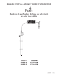
TMA-20HW Hot-Wire Anemometer 99 Washington Street Melrose, MA 02176 Phone 781-665-1400 Toll Free 1-800-517-8431 Visit us at www.TestEquipmentDepot.com Users Manual • • • • Mode d’emploi Bedienungshandbuch Manual d’Uso Manual de uso 1 TMA-20HW Hot-Wire Anemometer English Users Manual June 2010, Rev.1 ©2010 Amprobe Test Tools. All rights reserved. Printed in Taiwan Limited Warranty and Limitation of Liability Your Amprobe product will be free from defects in material and workmanship for 1 year from the date of purchase. This warranty does not cover fuses, disposable batteries or damage from accident, neglect, misuse, alteration, contamination, or abnormal conditions of operation or handling. Resellers are not authorized to extend any other warranty on Amprobe’s behalf. To obtain service during the warranty period, return the product with proof of purchase to an authorized Amprobe Test Tools Service Center or to an Amprobe dealer or distributor. See Repair Section for details. THIS WARRANTY IS YOUR ONLY REMEDY. ALL OTHER WARRANTIES - WHETHER EXPRESS, IMPLIED OR STAUTORY - INCLUDING IMPLIED WARRANTIES OF FITNESS FOR A PARTICULAR PURPOSE OR MERCHANTABILITY, ARE HEREBY DISCLAIMED. MANUFACTURER SHALL NOT BE LIABLE FOR ANY SPECIAL, INDIRECT, INCIDENTAL OR CONSEQUENTIAL DAMAGES OR LOSSES, ARISING FROM ANY CAUSE OR THEORY. Since some states or countries do not allow the exclusion or limitation of an implied warranty or of incidental or consequential damages, this limitation of liability may not apply to you. Repair All test tools returned for warranty or non-warranty repair or for calibration should be accompanied by the following: your name, company’s name, address, telephone number, and proof of purchase. Additionally, please include a brief description of the problem or the service requested and include the test leads with the meter. Non-warranty repair or replacement charges should be remitted in the form of a check, a money order, credit card with expiration date, or a purchase order made payable to Amprobe® Test Tools. In-Warranty Repairs and Replacement – All Countries Please read the warranty statement and check your battery before requesting repair. During the warranty period any defective test tool can be returned to your Amprobe® Test Tools distributor for an exchange for the same or like product. Please check the “Where to Buy” section on www.amprobe.com for a list of distributors near you. Additionally, in the United States and Canada In-Warranty repair and replacement units can also be sent to a Amprobe® Test Tools Service Center (see next page for address). Non-Warranty Repairs and Replacement – US and Canada Non-warranty repairs in the United States and Canada should be sent to a Amprobe® Test Tools Service Center. Call Amprobe® Test Tools or inquire at your point of purchase for current repair and replacement rates. TMA-20HW Hot-Wire Anemometer 15 2 4 5 3 7 6 8 1 10 9 11 12 13 14 13 1 Snake telescoping probe. 2 Display. 3 Power key : Push power key to turn the meter on or off. 4 H Hold key : Push H Hold key to freeze or unfreeze the display reading. In H mode, push UNIT key to select the desired unit of display. 5 key : Push key to turn on and off the backlight. 6 MX/MN key : Push “MX/MN” key to circulate the reading of Maximum, Minimum, Average and Current record mode. Push “MX/MN” key for 2 seconds to exit this mode. 7 SET key : Push “SET” key to enter setting mode. • Flow setup mode. • Select a time constant mode. • Select auto data memory interval time mode. • Auto power off time setting mode. • Backlight time setting mode. • Air velocity zero calibration mode. • Air velocity scale factor calibration mode. • Reset to factory default calibration value mode. 8 UNIT key : Push “UNIT” key to select the desired unit of measure. 9 FLOW key : Push “FLOW” key to select desired air velocity to determine the Air Flow. • 2/3V MAX : Use the maximum reading obtained to determine the 2/3V MAX Air Flow. • AVG : Use the average reading to determine the Air Flow. • Use the current reading to determine the Air Flow. 10 ↵ key : Enter / Exit a setting mode or store the displayed setting. 11 Test ID key : A group of samples. The statistics (maximum, minimum, average and count) are calculated for each TEST ID. The total number of TEST IDs is 10. Push “Test ID” key to select the desired TEST ID number from 0 to 9. 12 AUTO MEM key : • In the setting mode, push this key move flashing cursor to left. • In the TEST ID 0 to 4 mode, push this key one time store the one data to memory. • In the TEST ID number 5 to 9 mode, push this key to start auto data memory mode, push this key again to exit this mode. 13 keys : • In the setting mode, push “” keys to increase or decrease the displayed setting. • In the READ mode, push “” keys to select increase or decrease the memory address. 14 READ key : • In the setting mode, push this key move flashing cursor to right. • Push this key to enter the data memory READ mode, push this key again to exit this mode. 15 Sensor protection cap. Description of Display Air Velocity Display : : Auto power off indication. H : Data hold indication. SET : Setting mode indication. REC : Record mode and current air velocity measured display indication. REC MAX : Maximum air velocity measured display indication. REC MIN : Minimum air velocity measured display indication. REC AVG : Average air velocity measured display indication. (The average of the last 30 samples) Air Velocity Units : knots mile/hr : Miles per hour km/hr : Kilometers per hour ft/min : Feet per minute Bft : Beaufort scale m/s : Meters per second Flow Set Up Display : : Round Duct diameter dimension indication. X : Rectangle Duct X dimension indication. Y : Rectangle Duct Y dimension indication. Kf : K factor indication. AREA : Duct Area indication. m2 : Square meters ft2 : Square feet in : Inches cm : Centimeter Air Flow Display : 2/3V MAX : 2/3V Maximum mode is selected indication. AVG : Average mode is selected indication. : Current mode is selected indication. x 10 : Multiply reading by ten. x 100 : Multiply reading by one hundred. x 1000 : Multiply reading by one thousand. ft3/min : Cubic feet per minute. m3/min : Cubic meters per minute. Memory Display : TEST ID 0 – 4 : Manu data memory indication. TEST ID 5 – 9 : Auto data memory indication. SAMLE : Data memory number address indication. : Total average data number indication. M : Data memory indication, M display one time store one data into the memory. R : Data read mode indication. TC INTV s : Average time constant indication. : Auto data memory interval time indication. : Low battery indication. CONTENTS SYMBOLS................................................................................................................1 UNPACKING AND INSPECTION..............................................................................1 INTRODUCTION......................................................................................................2 OPERATION.............................................................................................................2 Getting Started..................................................................................................2 Settings and Calibrations...................................................................................2 Air Velocity Measurement.................................................................................5 Air Flow Measurement......................................................................................6 MAX/MIN/AVG Recording Measurement.........................................................6 Air Velocity Manual Data Memory and Read Mode . .....................................6 Air Flow Manual Data Memory and Read Mode ............................................7 Air Flow Auto Data Memory and Read Mode.................................................7 Clearing Memory...............................................................................................8 SPECIFICATION........................................................................................................8 MAINTENANCE AND REPAIR.................................................................................10 Trouble shooting................................................................................................10 Battery and Fuse replacement..........................................................................10 SYMBOLS � � Caution ! Risk of electric shock � Please remove all the test leads before preforming maintenance, cleaning, battery replacement, fuse replacement, etc � � Complies with European Directives = Caution ! Refer to the explanation in this Manual Conforms to relevant Australian standards Do not dispose of this product as unsorted municipal waste. Contact a qualified recycler for disposal �WARNING and PRECAUTIONS • Do not operate the meter in explosive gas (material), combustible gas (material) steam or filled with dust. • When using the meter to check air flow, make sure that you can safely raise and hold the meter while making measurements. Be careful when working on a ladder. • Observe all necessary precautions so that the unit does not become caught in moving machinery or touch any exposed electrical wiring. • The meter is not designed for use in gas mixtures other than air. Use with corrosive or other dangerous or explosive gas mixtures is not recommended. Unpacking and Inspection Your shipping carton should include: 1 TMA-20HW Hot-Wire Anemometer 1 Users Manual 6 AAA batteries 1 Carrying case If any of the items are damaged or missing, return the complete package to the place of purchase for an exchange. 1 INTRODUCTION The TMA-20HV Portable Air Velocity Meter is a lightweight instrument that can be used anywhere to measure air velocity. The meter uses a snake telescoping probe with a special sensor to accurately measure air velocity in different applications such as hood velocity, clean rooms, OSHA compliance, ventilation ducts and outlets, heating and air – conditioning, wind tunnels, product development, air – flow research and mass – flow measurement in ducts. OPERATION Getting Started 1. Installing the Batteries Insert (6) AAA batteries as indicated by the diagram located on the inside of the battery compartment. 2. Extending the Probe To extend the probe, hold the handle in one hand while pulling on the probe tip with the other hand. Do not hold the cable while extending the probe as this prevents the probe from extending. 3. Using the Snake Telescoping Probe The snake telescoping probe contains the air velocity sensor. When using the probe, remove the sensor protection cap then rotate or bend the snake tube, make sure the sensor window is fully exposed and the orientation is facing upstream. 4. Retracting the Probe To retract the probe, hold the handle in one hand while pushing on the probe tip with the other hand. If you feel the probe antenna binding, pull gently on the probe snake tube until the snake tube section is retracted. Collapse the rest of the antenna by pushing the probe tip. Settings and Calibrations Flow Set Up mode • Push key to turn on the meter. • Push “UNIT” key to select the desired measurement unit. 2 • Push “SET” key one time to enter the Flow Setup mode, the “ SET ” symbol is displayed. ), Duct Area There are 4 types : Round Duct ( ), Rectangle Duct ( (AREA), and K factor (Kf). • Push “” and “” keys to scroll through the choices and push “↵” key to confirm your choice. If round duct is chosen, the “ ” symbol will displayed. Use and keys to setting the size (diameter) from 1.0 to 635.0 cm or 1.0 to 250.0 inches. Push “↵” key to store the value. If rectangle duct is chosen, the “ X” symbol will displayed. Use and keys to setting the X – size of the duct, then push “↵” Y” key to store the value and advance to the next dimension, the “ symbol will displayed. Use and keys to setting the Y – size of the duct, then push “↵” key to store the value. If duct area is chosen, the “AREA” symbol will displayed. Use and keys to setting the value and decimal point of the duct area from 0.001 to 9999ft2 or 928m2, then push “↵” key to store the value. If K factor is chosen, the “Kf” symbol will displayed. Use and keys to setting the value and decimal point of the K factor from 0.001 to 9999, then push “↵” key to store the value. Note : Kf is the number by which the meter multiplies the velocity measurement to display volume. • Push “ SET ” key several times until the “ SET ” symbol is disappeared to exit the setting mode. Select a Time Constant mode • Push “SET” key two times to enter this mode, the “TC” symbol and the current time constant are displayed. • Push and keys to scroll through the choices and push “↵” key to store the choice. The choice for the time constant are : 1, 2, 3, 4, 5, 6, 7, 8, 9, 10, 15, 20, 25 and 30 seconds. • Push “SET” key several times until the “ SET ” symbol is disappeared to exit the setting mode. 3 The time constant is an averaging period. It is used to dampen the display. If you are experiencing fluctuating flows, a longer time constant will slow down those fluctuations.The average method is also referred to as a “moving average”. Select a Auto Data Memory Interval Time mode • Push “SET” key three times to enter this mode, the “INTV” symbol and the current interval time are displayed. • Push “” and “” keys to scroll through the log interval choices. The choice are : 1, 2, 3, 4, 5, 6, 7, 8, 9, 10, 15, 20, 25 and 30 seconds, and 1, 2, 3, 4, 5, 6, 7, 8, 9, 10, 15, 20, 25, 30 and 60 minutes. Push “↵” key to store the choice. • Push “SET” key several times until the “ SET ” symbol is disappeared to exit the setting mode. Auto Power Off Time Setting mode • Push “SET” key four times to enter this mode, the “APO” symbol and the current auto power off time are displayed. • Push “” and “” keys to setting the desired auto power off time from 1 to 50 minutes or setting to “– – m” for disable this function. Push “↵” key to store the setting. • Push “SET” key several times until the “ SET ” symbol is disappeared to exit the setting mode. Backlighting Time Setting mode • Push “SET” key five times to enter this mode, the “bL” symbol and the current backlight time are displayed. • Push “” and “” keys to setting the desired backlight time from 1 to 50 seconds or setting to “– – s” for disable this function. Push “↵” key to store the setting. • Push “SET” key several times until the “ SET ” symbol is disappeared to exit the setting mode. 4 Air Velocity Calibration mode • Push “SET” key six times to enter this mode, the “USEr CAL no” symbol is displayed. • Push “” and “” keys to select “ ” symbol is displayed. • Push “↵” key to enter the air velocity zero calibration mode, the “CAL 0” symbol is displayed. • Recover the sensor protection cap, until the air velocity reading is stable then push “↵” key to store the zero air velocity reading, and enter the air velocity scale factor calibration mode, the scale factor value is displayed. • Insert the meter probe into the tunnel with the sensor window toward the air flow. Secure the probe firmly with the velocity sensor placed where air speed is known. • Push , , and keys to setting the scale factor value until the display reading reaching desired value, then push “↵” key to store the scale factor value, “CAL PASS” will display one second. • Push “SET” key several times until the “ SET ” symbol is disappeared to exit the setting mode. Reset to Factory Default Calibration value mode • Push “SET” key seven times to enter this mode, the “dEF CAL” symbol is displayed. • Push “” and “” keys to select “ ” or “ ”, if select “ ” then push “↵” key will reset to factory default calibration value and exit setting mode. Air Velocity Measurement • Push key to turn on the meter. • The display will show the air velocity reading directly on the Air Velocity Display. • Push “UNIT” key to select the desired measurement unit. • Push “ H HOLD” key to freeze or unfreeze the display readings. In HOLD mode, the “ H ” symbol is displayed and push “UNIT” key to select another display units reading. 5 Air Flow Measurement AIR FLOW = (AIR VELOCITY) x (AREA) • Push key to turn on the meter. • The display will show the air velocity reading directly on the air velocity display. • The flow type setting is displayed on the flow set up display. • Push “FLOW” key to select the desired 2/3V MAX mode, AVG mode or current mode. If 2/3V MAX mode is chosen, the “2/3V MAX” symbol will displayed. The meter will use the maximum air velocity value obtained to determine the 2/3V MAX Air Flow. If average mode is chosen, the “AVG” symbol will displayed. The meter use air velocity average value (the last 30 samples) obtained to determine the Average Air Flow. If current mode is chosen, no symbol will displayed. The meter will use the current air velocity value obtained to determine the Current Air Flow. • The display will show the air flow reading directly on the Air Flow Display. MAX/MIN/AVG Recording Measurement • Push “MX/MN” key to enter the recording mode, the “ REC ” symbol is displayed and the auto power off function will be auto cancelled. • Push “MX/MN” key to circulated the display of the maximum ( REC MAX ), minimum ( REC MIN), average ( REC AVG ) and current ( REC ) air velocity reading. • Push “ H HOLD” key to paused recording, the “ H ” symbol is displayed, push “ H HOLD” key again will resume recording. • Push “MX/MN” key for 2 seconds to exit this mode. Air Velocity Manual Data Memory and Read Mode TEST ID 0 Memory Mode : • Push “Test ID” key to select the “TEST ID 0” memory. • Push “AUTO MEM” key each time, one set of reading to will be stored 6 to the memory. At this moment, display will show the “ M ” symbol one time and the memory address number. Total memory size is 99 sets. • Push “READ” key to enter READ mode, the display will show “ R ” symbol and the memory address number. Push or key to select the desired memory address number data for display. Push “READ” key again to exit the READ mode. Air Flow Manual Data Memory and Read Mode TEST ID 1 ~ 4 Memory Mode : • Push “Test ID” key to select the “TEST ID 1” memory. • Push “AUTO MEM” key each time, one set of reading to will be stored to the memory. At this moment, display will show the “ M ” symbol one time and the memory address number. Total memory size is 99 sets. If change to another Flow Set Up setting, the TEST ID will automatically increment. • Push “READ” key to enter READ mode, the display will show “ R ” symbol and the memory address number. Push “” or “” key to select the desired memory address number data for display. • Push “MX/MN” key to circulated the memory of the maximum (MAX) air velocity and air flow reading and the memory address number, the minimum (MIN) air velocity and air flow reading and the memory address number, and the average (AVG) air velocity and air flow reading and the total average samples. • Push “READ” key again to exit the READ mode. Air Flow Auto Data Memory and Read Mode TEST ID 5 ~ 9 Memory Mode : • Push “Test ID” key to select the “TEST ID 5” memory. • Push “AUTO MEM” key to start auto data memory mode, “INTV” symbol and current interval time are display, when “ M ” symbol flicks one time that means one set data has been memorized. Total memory size is 99 sets per each IDs. Push “AUTO MEM” key again to exit this mode. 7 If change to another Flow Set Up setting, the TEST ID will automatically increment. • Push “READ” key to enter READ mode, the display will show “ R ” symbol and the memory address number. Push “” or “” key to select the desired memory address number data for display. • Push “MX/MN” key to circulated the memory of the maximum (MAX) air velocity and air flow reading and the memory address number, the minimum (MIN) air velocity and air flow reading and the memory address number, and the average (AVG) air velocity and air flow reading and the total average samples. • Push “READ” key again to exit the READ mode. Clearing Memory • Push key to turn off the meter. • Push and hold down the “AUTO MEM” key then push key to turn on the meter to enter clear memory mode, “CLr no” symbol is displayed. • Push “Test ID” key to select the desired “TEST ID” to be clear. • Push “” key to select “ ” symbol is displayed. • Push “AUTO MEM” key to clear the memorized data. • Push “↵” key to exit the clear memory mode. SPECIFICATIONS General Specifications Display : Triple display, 4 digit LCD reading. Velocity Probe : Range : 0 to 30 m/s (0 to 600 ft/min) Resolution : 0.01 m/s (1 ft/min) Accuracy : ±3% of reading FS Duct Size : Range : 1 to 635 cm in increments of 0.1 cm. (1 to 250 inches in increments of 0.1 in.) Volumetric Flow Rate : Ranges : Actual range is a function of actual velocity, and dust size. 8 Warm up Time : < 1 minute Response Time : < 2 seconds Sampling Rate : One time per second. Manual Data Memory Capacity : 5 x 99 sets. Auto Data Memory Capacity : 5 x 99 sets. Operation Temperature Range : Meter : 0°C to 50°C (32°F to 122°F) Probe : -10°C to 60°C (14°F to 140°F) Storage : -20°C to 60°C (-4°F to 140°F) Operation Conditions : Altitude up to 2000 meters. Relative humidity up to 80%RH, non – condensing. Power Supply : 6 pcs 1.5V size AAA batteries. Battery Life : Approx. 10 hours. Probe Dimensions / Weight : Wire length : 2.2 meter (7.2 ft) Probe length : 1.2 meter (3.9 ft) Probe diameter of tip : 9.0 mm (0.35 in.) Probe diameter of base : 28.0 mm (1.1 in.) Probe weight : 165 g (0.36 lbs) Meter Weight / Dimensions : 235 g (0.52 lbs) 150(L) x 72(W) x 35(H) mm 5.9(L) x 2.8(W) x 1.4(H) inches Cenelec Direcives The instruments conform to CENELEC Low-voltage directive 73/23/EEC and Electromagnetic compatibility directive 89/336/EEC 9 �. EMC : EN 61326-1. This product complies with requirements of the following European Community Directives: 89/336/EC (Electromagnetic Compatibility) and 73/23/ EEC (Low Voltage) as amended by 93/68/EEC (CE Marking). However, electrical noise or intense electromagnetic fields in the vicinity of the equipment may disturb the measurement circuit. Measuring instruments will also respond to unwanted signals that may be present within the measurement circuit. Users should exercise care and take appropriate precautions to avoid misleading results when making measurements in the presence of electronic interference. MAINTENANCE AND REPAIR If there appears to be a malfunction during the operation of the meter, the following steps should be performed in order to isolate the cause of the problem. • Check the battery. Replace the battery immediately when the “ symbol appears on the LCD. ” • Review the operating instructions for possible mistakes in operating procedure. Except for the replacement of the battery, repair of the meter should be performed only by a Factory Authorized Service Center or by other qualified instrument service personnel. The front panel and case can be cleaned with a mild solution of detergent and water. Apply sparingly with a soft cloth and allow to dry completely before using. Do not use aromatic hydrocarbons or chlorinated solvents for cleaning. If the meter is not to be used for periods of longer than 60 days, remove the batteries and store them separately Trouble Shooting If the instrument fails to operate, check batteries and test leads etc., and replace as necessary. Double check operating procedure as described in this user’s manual. 10 Battery and Fuse replacement Battery use : Standard 1.5V AAA Size (NEDA 24G or IEC R03) battery X 6 Battery replacement : Loosen the 2 screws from the battery access door of the case bottom. Lift the battery access door and thus the battery compartment up. Replace the battery. Re-fasten the screws. 11 Visit us at www.TestEquipmentDepot.com