1
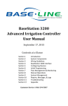
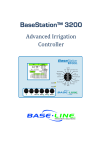
Baseline Inc. 1 WaterTec™ S100 User Manual Congratulations on selecting the WaterTec™ S100 kit, the industry’s leading soil-moisture sensing unit for residential and small commercial applications. The following manual guides you step by step through the installation process. You will also find troubleshooting information to further assist in your installation. For additional information, visit us online at www.baselinesystems.com. If you need assistance, please call us toll-free at 1.866.294.5847. Before You Get Started – Read the Entire Manual Before installing your new WaterTec S100, operate the sprinkler system to ensure the system is functioning properly and all heads are properly adjusted. For best results, you will need to know the application rate of your sprinklers as this usually varies greatly from zone to zone. Ideally each zone would receive the same amount of water (½” to ¾”). Baseline recommends that, prior to installation, you replace any backup batteries your sprinkler timer requires. You may need to refer to the original owner’s manual. ©2015, Baseline Inc. All Rights Reserved. WaterTec™, biSensor™, and biLine™ are trademarks of Baseline Inc. WaterTec S100 User Manual 2 Table of Contents Before You Get Started - Table of Contents 2, 3 S100 Display & Operational Features 4, 5 How to Get a Beautiful Lawn 6 Step 1 - Choose a Location for the biSensor 7 Step 2 - Mount & Wire the S100 8, 9 Step 3 - Connect the biSensor & Test Communication 10, 11 Step 4 - Bury the biSensor (Options A & B) 12, 13 Step 5 - Configure the Sprinkler Time & the Cycle Window 14 Step 6 - Calibrate the Sensor (Auto Calibration Mode) 15 Step 6 - Calibrate the Sensor (Manual Calibration) 16 Error Codes 17 Troubleshooting the WaterTec S100 18, 19 Baseline Inc. 3 Display & Operational Features A Display: By default, the display shows the soil moisture content that is present in the soil as measured by the biSensor™. A B The soil moisture value is displayed when no buttons are pressed or held. The soil moisture value is displayed volumetrically, ranging from 0.0 to 50.0. C D F E G To show current soil temperature in Celsius and Fahrenheit, press the + button. To display the number of days since the last and previous-to-last watering days, press the – button. A number 1 appears first, followed by the number of days since the last watering date. A number 2 appears next, followed by the number of days since the previous-to-last watering day. B Read/Set To have the biSensor take a moisture reading, briefly press the Read/Set button. To display the current moisture threshold value, press and hold the Read/Set button. C Moisture Threshold Adjustment: The value at which the S100 will allow watering. To adjust the moisture threshold, press and hold the Read/Set button, and then press the + or – button. WaterTec S100 User Manual 4 D Cycle Window: The cycle window is the amount of time allowed for a complete watering cycle to finish. While the cycle window is active, the value in the display alternates between the time remaining in the cycle and the current moisture reading. The S100 is preset for a 12-hour cycle window. To display the current cycle window duration, press and hold the Bypass button for 2 seconds. To change the cycle window duration to a value between 0 and 24 hours, press and hold the Bypass button, and then press the + or – button. E Bypass: Allows the sprinkler timer to operate without interruption from the S100. To toggle Bypass mode on/off, briefly press the Bypass button. When Bypass mode is enabled, the S100 display periodically flashes OFF and the Dry/Allow LED emits a double flash. F Busy: When this LED is lit, it indicates that the valve the sensor is attached to is currently watering. No automatic sensor readings will be taken while the Busy LED is lit. G Dry/Allow: When this LED is steadily lit, it indicates that the S100 is allowing your sprinkler timer to water based upon its user defined settings (the system will begin watering at the next start time programmed on the sprinkler timer). Auto Calibration: Used for initial installation or to recalibrate the biSensor. To put the S100 in Auto Calibration mode, press and hold the +, –, and Bypass buttons simultaneously for 3 seconds. The display will flash between CAL, 24 H, and the moisture reading. The 24 H will count down, on the hour, until the calibration is complete. Watering is stopped while the S100 is in Auto Calibration mode. For more information, refer to the Calibration section. Communication Test: Checks the biSensor for about 2 minutes for any potential errors. To initiate a communication test, press and hold the +, –, and Read/Set buttons simultaneously for 3 seconds. Refer to Testing Communication on page 10. Baseline Inc. 5 How to Get a Beautiful Lawn Watering SMART is a critical step towards a beautiful and healthy lawn. Water Less Frequently ● When you use the S100 to determine which days to water, the system will water only when needed, promoting deep roots, conserving water, and saving you money. Water Deeply Set your sprinkler timer to apply ½” to ¾” of water (use cups or cans to catch water for a fixed time to determine application rate, and then calculate an appropriate run time). Each zone may have a different water run time. Use “Soak Cycles” to minimize the amount of runoff. A typical soak cycle might be made up of two water periods each equal to ½ your total water time with one soak period equal to the total water time between the two water periods. For helpful suggestions on watering strategies, refer to Watering With Soil Moisture Sensors available on the Baseline website. http://www.baselinesystems.com WaterTec S100 User Manual 6 Step 1 – Choose a Location for the biSensor When planning the biSensor location, take into account variables such as sprinkler patterns, distribution uniformity, sun exposure and soil type, and other site specific characteristics that may affect water holding capacity or the rate at which plants use water. The location of the biSensor determines how frequently your sprinkler system is allowed to water. If the biSensor is placed in an area that is wetter than average, it will cause your system to operate less frequently, possibly causing dry spots. If the biSensor is placed in an area that receives less than average water, it will cause the system to operate more frequently. Baseline’s Recommendations for biSensor Placement Place the biSensor midway between two heads (the biSensor should only receive water from one zone). Place the biSensor in an area that receives average to slightly below average water. Keep away from sidewalks and driveways to avoid water from car washing or other factors. The maximum allowable wire distance between the biSensor and the S100 unit is 500 feet. The illustration to the right identifies heavy shadow and runoff areas in red and ideal biSensor locations in light green. Avoid red areas when installing your biSensor. Dark green areas with some shadow can be used as a secondary location. SENSOR LOCATION SENSOR LOCATION SECONDARY LOCATION SECONDARY LOCATION SENSOR LOCATION SENSOR LOCATION N Note: When installing the biSensor, connect it to the most convenient valve. The biSensor uses this connection to communicate with the S100 and the sprinkler timer. Baseline Inc. 7 Step 2 – Mount & Wire the S100 Mounting the S100 Mount the S100 near your sprinkler timer. If you mount the S100 outdoors, make sure that the control unit will not be exposed to spraying or dripping water. The unit is not waterproof! Do not mount the S100 in a below-grade location. Wiring the S100 to the Sprinkler Timer 1. On the sprinkler timer, disconnect the wire that is connected to the common terminal, and then connect that wire to the WHITE wire in the S100 bundle. 2. Connect the BLACK wire in the S100 bundle to the common terminal on the sprinkler timer. 3. On the sprinkler timer, find the terminal for the valve where the biSensor is connected. Disconnect the wire from that valve terminal, and then connect it to the RED wire in the S100 bundle. 4. Connect the GREEN wire in the S100 bundle to the terminal on the sprinkler timer that the valve wire was connected to. 5. Connect the ORANGE wire to the 24 volts AC (VAC) terminal on the sprinkler timer. If your sprinkler timer has more than one 24 VAC terminal, touch the orange wire to one of the terminals to find the one that supplies power. The S100 display will turn on when it receives power. 6. Optional: Connect the BLUE or BROWN wire to the terminal of a valve that you do not want under S100 control. The bypassed valve will operate solely based on the configuration in the sprinkler timer without any input from the S100. Do not disconnect the valve wires from the terminals of the valves that are bypassed. IMPORTANT! The only valve wire that you disconnect from the sprinkler timer is the one for the valve where the biSensor is connected. Leave all other valve wires connected to the timer. WaterTec S100 User Manual 8 Wiring the S100 Bypassing Zones Because the S100 works by interrupting the common wire in the valve circuitry, it controls watering for all zones on your system unless you bypass specific zones. The S100 allows you to designate two zones in your system that will operate solely based on the configuration in the sprinkler timer without any input from the S100. Connect the BLUE or BROWN wire to the valve terminal that you want to bypass. Do not disconnect the valve wire from these terminals. In the illustration below, the S100 will bypass valve 1 because the blue wire from the S100 is connected to that terminal and the yellow valve wire is also connected. To valve box S100 Wire Bundle ORANGE = power RED = sensor GREEN = valve terminal on timer BLACK = common to timer WHITE = common to valves BLUE & BROWN = bypass Baseline Inc. 9 Step 3– Connect the biSensor & Test Communication Connecting the biSensor 1. Determine which zone/valve operates the sprinklers in the location where the sensor will be buried. Note: The maximum allowable wire distance between the biSensor and the S100 unit is 500 feet. 2. Go to the box where that valve is located. 3. Disconnect the valve wiring inside the box noting which wire is common and which is “hot.” 4. Splice the black (or white) wire from the biSensor into the common wire connection. 5. Splice the red wire from the biSensor into the “hot” wire connection. Note: Make the initial connections with wire nuts, and then replace the wire nuts with waterproof connectors after you test the biSensor. Testing Communication Press and hold the +, –, and Read/Set buttons simultaneously for 3 seconds, and then release the buttons. The communication test causes the biSensor to take 100 readings. During the test, which takes about 2 minutes, the display alternates between SEn and a number that starts at 100 and counts down to 0. When the test is complete, the display alternates between Err and a number from 000 to 200, which indicates the number of errors. A reading of 000 is good — it indicates there were no errors. This error count stops displaying after 10 minutes. Note: Do not confuse the error count with the error type. Errors likely to occur at this stage are Er1, Er2, or Er3. See the Error Codes section for a description. To interrupt the communication test, press and hold the Read/Set button for 3 seconds. WaterTec S100 User Manual 10 Connecting the biSensor IMPORTANT! Do not bury the sensor yet! IMPORTANT! Make the initial connections with wire nuts, and then replace the wire nuts with waterproof connectors after you test the biSensor. Baseline Inc. 11 Step 4 – Bury the BiSensor (Option A) Option A works well in rocky soil. 1. Using a shovel or edger, cut out a piece of sod approximately 6” x 12” in the location where you plan to bury the biSensor. 2. Carefully remove the sod and try to keep the roots intact. 3. Dig a trench about 6” deep and the length of the biSensor in the exposed dirt. 4. Insert the biSensor into the trench. Stand the sensor on its long edge. If buried flat, biSensor readings can be wrong due to moisture pooling on surface of the biSensor. 5. Remove any rocks or gravel that are touching the surface of the biSensor to ensure there are no air pockets. 6. Cut a slit back to the valve box for the communication wires. Take care to bury them deep enough to avoid damage from aeration or other activities. 7. Using a bucket of water, saturate the soil surrounding the biSensor and compact the soil around it tightly. 8. Refill the hole, replace the sod, and saturate the area thoroughly. When the soil is saturated, compact it firmly around the biSensor. The biSensor must make good contact with the surrounding soil. WaterTec S100 User Manual Note: Ensure the biSensor is buried 2” - 3” below the grass line for optimal readings. This depth also helps prevent future damage from aeration or other activities. 12 Step 4 – Bury the BiSensor (Option B) Option B works well in sandy or loamy soils. 1. With a flat blade shovel, cut a slit in the grass where the biSensor will be placed. Widen the slit with a back and forth motion. 2. Place the biSensor in the slit horizontally so the top of the biSensor is 2”-3” deep. 3. Remove any rocks or gravel that are touching the biSensor to ensure there are no air pockets. 4. Cut a slit back to the valve box for the communication wires. Take care to bury them deep enough to avoid damage from aeration or other activities. 5. Using a bucket of water, saturate the soil surrounding the biSensor and compact the soil around it tightly. biSensor Burial Requirements Ensure there is good contact between the soil and the biSensor. Bury the biSensor so it is resting on its long edge. If the biSensor is buried flat, the readings can be wrong due to moisture pooling on the surface of the biSensor. Bury the biSensor 2” to 3” deep in turf areas and deeper for planters and tree areas (root zones). Baseline Inc. 13 Step 5 – Configure the Sprinkler Timer & the Cycle Window Configuring the Sprinkler Timer 1. Set your sprinkler timer to apply ½” to ¾” of water to each zone each day. By configuring your timer to water every day, you allow the biSensor to water on the best possible days. 2. Use “Soak Cycles” to minimize the amount of runoff. A typical soak cycle might be made up of 2 water periods each equal to ½ your total water time with one soak period equal to the total water time between the 2 water periods. 3. For helpful suggestions on watering strategies, refer to Watering With Soil Moisture Sensors on the Baseline website. http://www.baselinesystems.com Configuring the Cycle Window on the S100 The cycle window is the amount of time allowed for a complete watering cycle to finish after the first zone has started watering. Adjust the cycle window time to be at least one hour longer than the time required to finish watering. The S100 is preset for a 12-hour cycle window. If your system needs more than twelve hours to complete a watering cycle or if you choose to water your lawn several times per day, you may need to increase the cycle window duration. 1. Press and hold the Bypass button for 2 seconds. The current cycle window time displays. 2. While holding the Bypass button, press the + or – button to change the cycle window time. You can set a value between 0 and 24 hours. Note: When your system runs, if the moisture is still below the threshold when the cycle window is finished, the cycle window will start again if a valve is running. Set the cycle window for enough time to accommodate all watering needs plus an additional hour for padding. Manually Running a Zone Press the Bypass button on the S100 to turn off the biSensor control and prevent a cycle window from starting. Then use the controls on your sprinkler timer to start the manual run. When the manual run is complete, press the Bypass button on the S100 again to enable biSensor control. WaterTec S100 User Manual 14 Step 6 – Calibrate the Sensor (Auto Calibration Mode) The S100 has an Auto Calibration mode that runs for 24 hours. Auto calibration sets the moisture threshold based on your soil type. This is important for new installations and useful for recalibrating a biSensor. 1. Heavily saturate the soil around the biSensor with water. If the soil is not properly saturated, the auto calibration will fail. 2. After the water has soaked into the soil, briefly press the Read/Set button on the S100 to take the current moisture reading. Write down the current date, time, and moisture reading to be used as a reference point. Date:_______________ Time:__________ Moisture Reading:___________ 2. Press and hold the +, –, and Bypass buttons simultaneously for 3 seconds. The display will flash between CAL, 24 H, and the moisture reading. The display will count down, on the hour, until the calibration is complete. Watering is stopped while the S100 is in Auto Calibration mode. Do not allow the biSensor to receive any water during calibration. This process will fail or provide false feedback if it does. Notes on the Auto Calibration Process To exit the Auto Calibration mode, press and hold the Read/Set button for 3 seconds. If the calibration succeeds, the moisture threshold will be automatically set, and the system will allow watering when soil moisture drops below this threshold. If an error occurs during auto calibration, the screen will flash Er4 indicating that calibration failed. The Er4 code is followed by another code with a number that corresponds to the reason for failure. See the Troubleshooting section for information on the various error messages. If the auto calibration fails, the S100 will water based on the previously set threshold. If the biSensor receives water during the 24 hour calibration period, or the soil was not totally saturated, the calibration will either fail entirely or set an incorrect threshold for your lawn. If this happens, you will need to re-saturate the soil and restart the auto calibration. If the threshold set by the auto calibration is unacceptable, try the manual calibration process described on the next page. Baseline Inc. 15 Step 6 – Calibrate the Sensor (Manual Calibration) If the auto calibration does not set an acceptable threshold, you might want to perform the following manual calibration procedure. 1. Bury the sensor as described in Step 4 (on pages 12—13) using a full bucket of water to remove air pockets around the sensor. 2. Put the S100 in Bypass mode. To enable Bypass mode, briefly press the Bypass button. When Bypass mode is enabled, the S100 display periodically flashes OFF and the Dry/Allow LED emits a double flash. 3. Configure the sprinkler timer to water using soak cycles and allowing ½” to ¾” of accumulated water for the cycles. 4. Run the system. 5. When watering has finished, turn off the sprinkler timer and take the S100 out of Bypass mode. To disable Bypass mode, briefly press the Bypass button. When Bypass mode is disabled, the S100 returns to the default display. 6. Carefully watch your landscape. When it gets to the point where you think that you cannot wait another day to water, briefly press the Read/Set button on the S100 to display the current moisture reading. Remember or write down this reading. 7. Press and hold the Read/Set button, and then press the + or – button to adjust the threshold to match the moisture reading from the previous step. 8. Turn the sprinkler timer back on. The system will water at the next start time and then maintain the moisture at your acceptable threshold. Manually Adjusting the Threshold As the grass roots grow back around the biSensor, you might need to manually adjust the threshold. Observe lawn conditions, and then adjust the threshold as needed. Raising the threshold results in more frequent watering. Lowering the threshold results in less frequent watering. 1. Take a biSensor reading after a watering cycle. Briefly press the Read/Set button and note the reading that displays. 2. Press and hold the Read/Set button, and then press the + or – button to adjust the threshold slightly above or below the current moisture reading (an adjustment of 0.5 - 1.0 points is all that should be necessary). WaterTec S100 User Manual 16 Error Codes An error code on the S100 warns that an irregular condition has occurred. Even though your irrigation system will continue to water when an error code displays on the S100, you should refer to the Error Code table below and the Troubleshooting section on pages 18 - 19 to determine the status of the S100 and take action as necessary. To clear an error code, briefly press the Read/Set button. Error Code Er1 Er2 Er3 Status Communication Error Over Current Error Cause Incorrect Wiring Bad Connections Damaged Wire Bad Valve Solenoid Short Circuit Wires Bad Reading from biSensor biSensor stick is damaged biSensor is not buried in the ground Er4 24-hour Auto Calibration Failed This error also displays one of the other error codes listed in this table to indicate the reason for the failure Er5 Value Out of Range Error during the 24-hour Auto Calibration This indicates the biSensor readings fall outside of the expected range. Can be caused by failure to saturate the soil in the beginning or by the watering of the site during calibration. If an ER4 occurred, the S100 will water based on the previously set threshold. Low Reading during the 24- hour Auto Calibration This indicates that there was a low reading during calibration. Re-run the auto calibration. Er6 Baseline Inc. Remove any air pockets around sensor. 17 Troubleshooting the WaterTec S100 Error Code or Condition Er1 is displayed Er2 is displayed Er3 is displayed Er4 is displayed Status The S100 cannot communicate with the biSensor. The S100 has detected excessive current while trying to communicate with the biSensor. biSensor is reading an invalid moisture level. There was a problem during the 24-hour auto calibration WaterTec S100 User Manual Recommended Action Double-check the wiring for corrosion and the waterproof connections to the biSensor. Check biSensor for damage. Ensure the biSensor is in contact with soil/moisture. After making repairs, run the Communication Test. Verify connections inside the valve box are tight. Check for a faulty valve solenoid. Check for lightning damage. Double-check the wiring and connections to the biSensor. Inspect the biSensor and replace if necessary. Ensure biSensor is buried properly. This error is accompanied by one of the other error codes. Refer to the secondary Er# for possible solution. 18 Error Code or Condition Status Recommended Action Er5 is displayed (Press Read/Set to clear this warning message.) Unexpected reading during 24-hour auto calibration – final reading was not substantially different from the first. Make sure no extra water is applied to the biSensor after auto calibration starts or the S100 may set a unacceptable threshold. Er6 is displayed Unexpected low reading during the 24-hour auto calibration. Ensure soil is compacted around sensor with not air pockets or rocks touching. Re-saturate soil, and then re-run the 24–hour auto calibration. Make sure the 24 VAC transformer is plugged in and receiving power Ensure the 24 VAC wire and common wire from the S100 are properly connected. biSensor is reading There may be air pockets a value under 20 around the biSensor. Soil appears wet Re-bury the biSensor. Be especially careful that NO rocks are touching the blade of the sensor as this can lead to false readings. Controller does Some older mechanical not have access to controllers do not have 24 VAC access to 24 VAC. Purchase and install a 24 VAC transformer. For more information, contact Baseline support at 866-294-5847. Display is blank LEDs are off Baseline Inc. S100 is not receiving 24 VAC. 19 WaterTec S100 User Manual 20