1
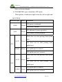
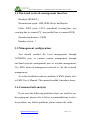
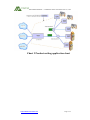
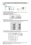
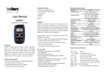
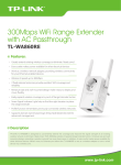
SHENZHEN MISENSE
COMMUNICATION TECHNOLOGY CO., LTD.
User's Manual
For MS-E8221
Version:V1.0
WWW.MISENSECOM.COM
SHENZHEN MISENSE
COMMUNICATION TECHNOLOGY CO., LTD.
CONTENT
1.
PRODUCT INTRODUCTION .............................................................................................................1
1.1
Product summarise ..............................................................................................................1
1.2
Functional features..............................................................................................................1
1.2.1.
EPON port Functional features.......................................................................................1
1.2.2.
Functional features of other ports ...................................................................................4
1.3
2
3
Size and weight ....................................................................................................................6
EQUIPMENT INSTALLATIONS .........................................................................................................6
2.1
Installation enviroment ........................................................................................................6
2.2
EPON Port connection ........................................................................................................6
2.3
Uplink SFP installation .......................................................................................................7
2.4
Equipment electrify..............................................................................................................8
2.5
Power requiement................................................................................................................8
2.6
Equipment electrify..............................................................................................................8
TECHNOLOGY SPECIFICATIONS......................................................................................................9
3.1
EPON optical port specification..........................................................................................9
3.2
Up link data port................................................................................................................10
3.3
Console interface...............................................................................................................10
3.4
Out-band network management interface.......................................................................... 11
3.5
Management configuration: .............................................................................................. 11
3.6
Common fault analysis ...................................................................................................... 11
APPENDIX A SECURITY PROMPT .........................................................................................................14
APPENDIX B TROUBLE HANDLING.......................................................................................................14
APPENDIX C PRODUCT APPLICATION ...................................................................................................15
WWW.MISENSECOM.COM
SHENZHEN MISENSE
COMMUNICATION TECHNOLOGY CO., LTD.
1. Product introduction
1.1 Product summarise
MS-E8221 is the Central Office mainfram box platform of
GEPON series products which is researched and developed by
our company; it is Able to provide a variety of integrated
services access, such as broadband, voice, IPTV, CATV.
It includes 2 independent fiber terminals (OLT) unit and 2
SFP GE uplink port, 1 console port, 1 Of-band management port,
1 RS485 port.
All the GEPON series products of our company are using
passive optical network (PON) technologies, which is better
than
traditional
access
products
in
cost
performance,
maintenance, expansibility and etc.
1.2 Functional features
1.2.1. EPON port Functional features
In GEPON system, as the OLT unit, PON port is responsible
for the register of ONU, transfers the Ethernet message received
from network in the downlink to EPON optical signal, and sent
it to ONU by passive network. In up link,
WWW.MISENSECOM.COM
Page 1/16
SHENZHEN MISENSE COMMUNICATION TECHNOLOGY CO., LTD.
it receives EPON optical signal sent by ONU and transfer it to
ethernet message then send to swich core equipment.
It includes 2 PON port of 1.25G; usually each PON port
can access 32 pieces of ONU equipment in the transmission
distance of 20kms.
The equipment is composed by high integrated OLT chips
and independent control modules, offering reliable assurance
for users in functions and performences.
The functional features of this board are summerized as
follows:
¾ Support ONUs communicate under the same PON port
¾ Support 802.3 MPCP protocal
¾ Support 802.3 OAM and expand protocal(slave port),
have
abundent
OAM
function
design,
offer
long-distance management through OLT
¾ Have double-channal independent OLT
¾ Support long-distance update for software
¾ High integration level and integration management,
and have the function of double layer exchange
¾ Support data encrypt service in downlink, secure the
data transition security for users
¾ Support ONU authentication, avert illegal ONU
WWW.MISENSECOM.COM
Page 2/16
SHENZHEN MISENSE COMMUNICATION TECHNOLOGY CO., LTD.
accesss to network
¾ Support DBA dynamic bandwidth allocation
¾ Support IGMP Proxy
¾ Support ACL functions
¾ Support QOS functions
¾ Support 4K MAC address with single channal OLT
¾ Support VLAN divided by LLID
¾ Offer abundant statistical information
¾ Support hot plug by the board
¾ Offer 2G uplink
¾ The uplink is SFP, and could be configured as
electrical port or optical port
¾ If configured as electrical port,it should work as the
pattern of 1000M
¾ Support the VLAN division on the basis of port
¾ Support 4096 entries of VLAN
¾ The capacity of MAC address is 8K
¾ Uplink support port trunk, port monitoring and
mirroring
¾ Offers 2 control interface, local and network
¾ Support 3 types of management CLI, TELNET and
SNMP
WWW.MISENSECOM.COM
Page 3/16
SHENZHEN MISENSE COMMUNICATION TECHNOLOGY CO., LTD.
¾ The net Work control supports in-band and out-band
Support read of SFP mode
1.2.2. Functional features of other ports
The sketch map of front panel is as follows:
Chart 1 Product appearance diagram
Descriptions of the interface
From left toright, the discriptions are as follows:
¾ The RS485 interface, use to transfer serial informations
from ONU
¾ RST button, press this button to trigger the board
restoration
¾ Consloe port, local management interface, RS232,
connector type RJ45
¾ Manage
port,
out-band
management
interface,
10M/100M full or duplex ethernet interface, connect
type: RJ45
¾ GE1&GE2 port, uplink, SFP mode, it can configured as
WWW.MISENSECOM.COM
Page 4/16
SHENZHEN MISENSE COMMUNICATION TECHNOLOGY CO., LTD.
fiber or electical mode
¾ PON1&PON2 port, downlink, SFP mode
Discriptions of indicator lights from the left to right and
up to down
Indicator light
color
Definition
Off: power is abnomal
PWR
Green
On: power is nomal
Off: abnormal system operation
SYS
Green
On: normal system operation
Flash: there are data passing from uplink
port
ACT1
Green
Off: there are no data passing from
GE1
uplink port
LINK1 Green
On: uplink port is connect
Off: uplink port isn’t connect
Flash: there are data passing from uplink
port
ACT2
Green
Off: there are no data passing from
GE2
uplink port
On: uplink port is connect
LINK2 Green
Off: uplink port isn’t connect
WWW.MISENSECOM.COM
Page 5/16
SHENZHEN MISENSE COMMUNICATION TECHNOLOGY CO., LTD.
On: The first port connected to ONU
PON1 LINK1 Green
Off: The first port not connected to ONU
On: The second port connected to ONU
PON1 LINK2 Green Off: The second port not connected to
ONU
Table 1 the discription of indicator lights of panel
1.3 Size and weight
Size: 441mm*192mm*43mm
Weight:
about 3kg
2 Equipment installations
2.1 Installation enviroment
Installed in the center room on the rack.
2.2 EPON Port connection
First install the OLT SFP optical module, and after
installing the optical module, insert SC/PC fiber to SFP optical
mode, and the process is completed.
Note: Keep the joint of fiber clean, and please preserve
the cap of flange for later use.
WWW.MISENSECOM.COM
Page 6/16
SHENZHEN MISENSE COMMUNICATION TECHNOLOGY CO., LTD.
2.3 Uplink SFP installation
The uplink port of the board is SFP interface, the default
option of the board before leaving the factory is no SFP
module, users could use proper SFP module according to his
own situations.
SFP is standard parts, when you install it, directly inserting
it to the SFP slot of the board. The board could identify that the
module which the user insert is optical module or electrical
module.
In default conditions, the board works in the normal
exchange mode, in that mode, the 2 SFP interfaces of board are
same, and the uer could use any one of it. But in isolation and
converge mode, user should choose the specific port
In isolation mode, the corresponding relations of up link
ports and PON ports are as follows:
SFP uplink port
PON port
GE1
PON1
GE2
PON2
Table 2 the corresponding table of ports
WWW.MISENSECOM.COM
Page 7/16
SHENZHEN MISENSE COMMUNICATION TECHNOLOGY CO., LTD.
2.4
Equipment electrify
SFP up link port: on the basis of different type of modules,
use net cable or optical fiber to connect up link port and
up-layer network equipment (such as switch, router).
CONSOLE port: use the DB9/RJ45 special connection
cable which is the accessory of the equipment to connect
CONSOLE port and DB9 interface of PC.
Manger port: use crossing-line or parallel line to connect
this port with PC or HUB.
NOTE: The net cable or fiber is no available when the
machine left the factory, and the user needs to prepare it.
2.5 Power requiement
The power of the board is supplied by common AC power
range is from: AC100V~AC250V
Power consumption: < 15W
2.6 Equipment electrify
The board supports hot plug, and when the power is
applied to it, you could judge if it works normally or not
through the indicator light conditions. If the board has already
connected with power or started to work, the conditions of
WWW.MISENSECOM.COM
Page 8/16
SHENZHEN MISENSE COMMUNICATION TECHNOLOGY CO., LTD.
indicator lights should be like the follows:
¾ The power indicator light of the board is on
¾ At this time whether the EPON optical port is connected
or not, the link light should be off temporarily
¾ The board’s initialization is completed no more than 20
Second, and if the equipment has be connected with
ONU equipment normally, the LINK indicator light of
EPON port of OLT should be on, with means the ONU
has connected to OLT normally.
3 Technology specifications
3.1 EPON optical port specification
Number of EPON optical port: 2
Parameter of EPON optical port:
Parameter
specification
Module type
1000Base-PX20 or 1000Base-PX10
Connection type
SC/PC
Extents
of
optical Send : 1480nm~1500nm
wavlength
Receive: 1260nm~1360nm
Tansmission distance
According to the different optical module
it could be 10km or 20km
WWW.MISENSECOM.COM
Page 9/16
SHENZHEN MISENSE COMMUNICATION TECHNOLOGY CO., LTD.
Dispatch optical power
Refer to SFP optical module specification
Receive sensibility
Refer to SFP optical module specification
Saturation optical power
Refer to SFP optical module specification
Table 3 EPON Optical Port Parameters
3.2 Up link data port
Number of ports: 2
Form: SFP power supply
Voltage: 3.3V
Interior signal interface: SGMII
Supporting module: SFP optical module or SFP electrical
module
Working speed:
Optical module: 1000M/ full duplex.
Electrical module: 1000M/full duplex
3.3 Console interface
Interface type: RJ45
Switch line: RJ45/DB9, use the special connection cable
which is configured by the factory, signal level standard is
RS232.
WWW.MISENSECOM.COM
Page 10/16
SHENZHEN MISENSE COMMUNICATION TECHNOLOGY CO., LTD.
3.4 Out-band network management interface
Standard: IEEE802.3
Transmission speed: 10M/100M full or half duplex
Cable: RJ45 joint, CAT5 non-shield crossing-line, use
crossing-line to connect PC, use parallel line to connect HUB.
Tansmission distance: 100M
Number of port: 1
3.5 Management configuration:
You should conduct the local management through
CONSOLE port, or connect remote management through
out-band network management port or in-band management.
Use EMS network management network to do the network
management.
As to the installation and use methods of EMS, please refer
to EMS User’s Manual. This manual wouldn’t introduce more.
3.6 Common fault analysis
If you meet the following problems when you install or use
the equipment, please refer to below recommendations to solve
the problem, any further problems, please contect the seller.
WWW.MISENSECOM.COM
Page 11/16
SHENZHEN MISENSE COMMUNICATION TECHNOLOGY CO., LTD.
Common fault
Fault resolution recommendation
CONSOLE
Check whether the connection cable is
Connection is
proper or not, if the parameter of band
not succesful
rate is set correctly, please use the
special connection cable which is
offered by the factory, The work
bandrate of CONSOLE port is 115200
When up link
Check the connections on whether to
connect to SFP
support Gigabit, only each other to
electrical module, it
support gigabit mode to be able to
only works in 1000M
connect
Could not be connected Check the cable,use the crossing cable
to the out-band network
when connected to PC, use parallel to
Management interface
connected to HUB
Could not be connected Check if the parameter of optical power
when use SFP optical parameter is matched the requests of
module
module specification, if input optical
power is more than module sensibility
if it is less than the optical module
saturation.
In addition, it is possible that the SFP
module has been damaged, so please
WWW.MISENSECOM.COM
Page 12/16
SHENZHEN MISENSE COMMUNICATION TECHNOLOGY CO., LTD.
ensure the SFP module could work
normally. Abserve the problem still
exist after replace the SFP module , if
Still could not solve the problem please
seek our technology supporter
Table 4 Common fault and resolution recommendation
WWW.MISENSECOM.COM
Page 13/16
SHENZHEN MISENSE COMMUNICATION TECHNOLOGY CO., LTD.
Appendix A Security Prompt
¾ Please read this manual carefully, and install and use the
equipment according to the discription of this manual
¾ Please don’t install this product in an enviroment which
is too moist (coagulate)
¾ Please don’t touch optical dispacher module with your
hands, in case the static damages the optical parts
¾ After the EPON OLT gets power, do not looking at the
optical outlet directly in case the eye get hurt
¾ Please don’t curve optical fiber in random, and the
curving radius of the fiber should be not less than
38mm
¾ Before connecting with the fiber, please don’t pull out
the hat of flange, in case the end surface of fiber is
polluted.
Appendix B Trouble handling
If you meet the following problems when you installed
and use the board, please refer to the trouble handing
recommendation below, if you have more questions and
problem, please contact the person who sell this equipment
to you.
WWW.MISENSECOM.COM
Page 14/16
SHENZHEN MISENSE COMMUNICATION TECHNOLOGY CO., LTD.
Trouble
Trouble handling
PWR light is off
z Check the whether the power connector is
plugged in
z Check the swicth button is ON
EPON optical port z Check is the time of the power connection
LINK light is off
exceeds 20 seconds
z Check if it has been connected to ONU
z Check if the joint of fiber matched the
optical module interface
z Check if the loss of optical fiber is
exaggerated and if the sensibility of receive
optical power is less than that of the optical
receive
The rate of data Check if the touchment of the optical joint is
packet loss is too OK
high
Table 5 Touble handling of OLT equipment
Appendix C Product application
WWW.MISENSECOM.COM
Page 15/16
SHENZHEN MISENSE COMMUNICATION TECHNOLOGY CO., LTD.
Chart 2 Product netting application chart
WWW.MISENSECOM.COM
Page 16/16