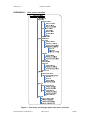
1
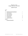
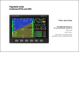
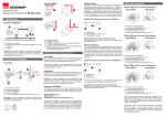
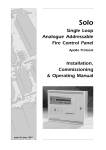
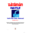
Created by: A.C.
Revised by: G.G.
Checked by: JBJ/PB
Approved by: JBJ
Control Equipment Limited
96 Zone Discovery Panel, 32 Zone Voyager
Panel and Integra Network Repeater 40Character
User Manual
Table of Contents
1. Introduction..............................................................................................................3
2. Panel Events ...........................................................................................................3
2.1 The Fire Condition ............................................................................................3
2.2 The Alert Condition...........................................................................................4
2.3 The Fault Condition ..........................................................................................5
2.4 The Maintenance Condition..............................................................................6
2.5 The System Fault Condition .............................................................................7
2.6 Quiescent Condition .........................................................................................7
2.7 Access Mode ....................................................................................................7
3. Routine Maintenance...............................................................................................8
3.1 Daily Attention ..................................................................................................8
3.2 Weekly Attention...............................................................................................8
3.3 Quarterly Inspection .........................................................................................8
3.4 Annual Inspection .............................................................................................8
3.5 Battery Replacement ........................................................................................8
4. Overview Of User Functions....................................................................................8
4.1 Change Time And Date ....................................................................................8
4.2 Delay Of Operation Of Outputs ........................................................................8
4.3 Adjustable Sensitivity Modes............................................................................9
4.4 Enabling And Disabling Of Functions ...............................................................9
4.5 The Event Log ..................................................................................................9
4.6 Test Functions ................................................................................................10
4.7 View Suppressed Events................................................................................10
4.8 Printer Functions ............................................................................................10
5. User Controls and Indications ...............................................................................11
6. User Functions ......................................................................................................13
6.1 How To Enter Numbers ..................................................................................13
6.2 How To Set The Time And Date.....................................................................13
6.3 How To Enable And Disable The Panel Delay ...............................................14
6.4 How To Enable Day Sensitivity Mode. ...........................................................15
6.5 How To Enable Night Sensitivity Mode. .........................................................15
6.6 How To Enable Timed Sensitivity Mode.........................................................16
6.7 How To Enable Off Sensitivity Mode. .............................................................16
6.8 How To Change The Baud Rate. ...................................................................17
6.9 How To Access The Disablement Menu Via The Summary Screen. .............17
6.10 How To Enable And Disable A Single Point (Stand-Alone Panel)..................18
6.11 How To Enable And Disable A Single Point (Network Panel) ........................18
6.12 How To Enable And Disable A Range Of Points (Stand-Alone Panel) ..........19
6.13 How To Enable And Disable A Range Of Points (Network Panel) .................20
6.14 How To View Disabled Points ........................................................................22
Document Number: USDV40 Rev.: 1
Page 1 of 46
16/2/09
Written by: A.C.
Checked by: JBJ/PB
6.15 How To Enable All Points (Stand-Alone Panel)..............................................22
6.16 How To Enable All Local Points (Network Panel)...........................................23
6.17 How To Enable All Points Globally (Network Panel) ......................................23
6.18 How To Enable All Points At Selected Panel (Network Panel).......................24
6.19 How To Enable And Disable A Zone Of Devices (Stand-Alone Panel) ..........25
6.20 How To Enable And Disable A Zone Of Devices (Network Panel).................25
6.21 How To Enable And Disable A Range Of Zones (Stand-Alone Panel) ..........26
6.22 How To Enable And Disable A Range Of Zones (Network Panel) .................27
6.23 How To View Disabled Zones ........................................................................28
6.24 How To Enable And Disable The Local Printer ..............................................29
6.25 How To Enable And Disable All Sounding Devices........................................30
6.26 How To Enable And Disable An Expansion Board Input (Stand-Alone Panel)30
6.27 How To Enable And Disable An Expansion Board Input (Network Panel) .....31
6.28 How To Enable And Disable A Range Of Expansion Board Inputs (StandAlone Panel) ...........................................................................................................32
6.29 How To Enable And Disable A Range Of Expansion Board Inputs (Network
Panel)......................................................................................................................33
6.30 How To View Disabled Expansion Board Inputs ............................................34
6.31 How To Enable And Disable All Non-Sounder Devices .................................35
6.32 How To View The Event Log ..........................................................................35
6.33 How To View Suppressed Alerts, Faults And Indications...............................36
6.34 How To View Suppressed Disablements .......................................................36
6.35 How To View The Status Of A Point...............................................................37
6.36 How To Test Devices Using One Person Test Mode .....................................40
6.37 How To Test Sounding Devices Using One Person Test Mode.....................41
6.38 How To Test Discovery Sounder Beacon Devices Using Magnetic Wand.....41
6.39 How To Clear The Print Queue ......................................................................42
6.40 How To Print The Event Log ..........................................................................42
6.41 How To Print Disablements ............................................................................43
APPENDIX A - Discovery Mechanical and Environmental Specification ..................44
APPENDIX B - Voyager Mechanical And Environmental Specification ....................44
APPENDIX C - List of Message Abbreviations..........................................................45
APPENDIX D - User menu overview .........................................................................46
Document Number: USDV40 Rev.: 1
Page 2 of 46
16/2/09
Written by: A.C.
Checked by: JBJ/PB
1. Introduction
Thank you for purchasing this CEL control panel.
This document contains all the information necessary for the end user to operate the
Discovery and Voyager control panels and Integra network repeater using Phase 6
software –i.e. version 955790**. [**= issue level]. These panels are functionally
identical and differ only in the number of loops and the physical packaging.
Warning: This equipment contains dangerous voltages. To prevent electric
shock do not open the display door. No user-serviceable parts inside – for
servicing contact suitably qualified personnel.
2. Panel Events
This section describes how events are reported and how the user should respond.
2.1 The Fire Condition
When a fire condition is detected automatically by a sensor, operation of a manual
call point or operation of the evacuate switch the panel responds as follows.
•
The COMMON FIRE and relevant zone LEDs pulse.
•
The internal buzzer sounds intermittently if the device is allocated to a zone.
•
The top three lines of the LCD display details of the event, while the bottom
line identifies the event category and its position in the queue.
•
1:001 Z01 OPT FIRE
DEVICE LOCATION OVER
TWO LINES
FIRE EVENT 01 OF 01
The sounder circuits are operated (see Note below).
•
System outputs are operated according to the panel programming (see Note
below).
•
The event is printed if a printer is fitted.
The top three lines retain the first fire information. Line 4 will update the number of
fire events if further events occur. The scroll messages key will scroll current fires in
the window.
During a fire condition the display of events of a lower priority is suppressed. To view
these events refer to section 6.33.
Note:- The fire and alarm relays, and the cause/effect outputs, may be delayed via
the Panel Delay function. The general fire relay will not operate for evacuate if the
evacuate mode is configured as partial.
User Actions
Carry out the required fire drill.
If a printer is fitted the user actions will be printed out in addition to the
automatic system events.
Document Number: USDV40 Rev.: 1
Page 3 of 46
16/2/09
Written by: A.C.
Checked by: JBJ/PB
2.2 The Alert Condition
A pre-alarm is indicated if the analogue value of a smoke detector rises above a predetermined level, but not sufficiently to indicate a fire condition. It may indicate that a
fire condition is imminent.
The panel responds as follows:
•
The ALERT LED pulses.
•
The internal buzzer sounds continuously.
•
The LCD displays details of the event.
•
1:001 Z01 OPT ALERT
DEVICE LOCATION OVER
TWO LINES
ALERT EVENT 01 OF 01
The event is printed if a printer is fitted.
•
Subsequent events will be displayed in the same way as for fire events.
During an alert condition the display of events of a lower priority is suppressed. To
view these events refer to section 6.33.
User Actions
•
Switch the ACCESS CONTROLS keyswitch to the ON position to enable the
controls.
•
Press the SILENCE BUZZER switch.
The BUZZER SILENCED LED illuminates.
The internal buzzer silences.
•
Investigate and rectify the cause of the alarm.
•
When the cause of the alarm is cleared press the RESET switch to return the
system to the quiescent condition.
•
Record the event in the system log book.
If a printer is fitted the user actions will be printed out in addition to the
automatic system events.
Document Number: USDV40 Rev.: 1
Page 4 of 46
16/2/09
Written by: A.C.
Checked by: JBJ/PB
2.3 The Fault Condition
A fault is indicated if any part of the system enters an abnormal condition.
The panel responds as follows:
•
The COMMON FAULT LED pulses. If the fault is with an alarm circuit the
ALARM FAULT/DISABLEMENT LED will also pulse.
•
The internal buzzer sounds continuously.
•
The LCD displays details of the event.
•
1:001 Z01 OPT FAULT
DEVICE LOCATION OVER
TWO LINES
FAULT EVENT 01 OF 01
The event is printed if a printer is fitted.
During a fault condition the display of events of a lower priority is suppressed. To
view these events refer to section 6.33.
User Actions
•
Switch the ACCESS CONTROLS keyswitch to the ON position to enable the
controls.
•
Press the SILENCE BUZZER switch.
The BUZZER SILENCED LED illuminates.
The internal buzzer silences.
•
Investigate and rectify the cause of the fault. If the fault cannot be rectified
immediately determine the area affected by the fault and decide whether
special action (such as fire patrols) are needed in that area.
•
When the cause of the fault is cleared press the RESET switch to return the
system to the quiescent condition.
•
Record the event in the system log book.
If a printer is fitted the user actions will be printed out in addition to the
automatic system events.
Document Number: USDV40 Rev.: 1
Page 5 of 46
16/2/09
Written by: A.C.
Checked by: JBJ/PB
2.4 The Maintenance Condition
A maintenance fault is indicated when a Discovery smoke detector reaches its
calibration limits. It can indicate that the device is contaminated and requires cleaning
or replacing. The device is still able to detect a fire condition.
The panel responds as follows:
•
The MAINTENANCE LED pulses.
•
The internal buzzer sounds continuously.
•
The LCD displays details of the event.
•
1:001 Z01 OPT DIRTY
DEVICE LOCATION OVER
TWO LINES
IND EVENT 01 OF 01
The event is printed if a printer is fitted.
User Actions
•
Switch the ACCESS CONTROLS keyswitch to the ON position to enable the
controls.
•
Press the SILENCE BUZZER switch.
The BUZZER SILENCED LED illuminates.
The internal buzzer silences.
•
Call your service engineer to service the device.
•
When the cause of the fault is cleared press the RESET switch to return the
system to the quiescent condition.
•
Record the event in the system log book.
If a printer is fitted the user actions will be printed out in addition to the
automatic system events.
Document Number: USDV40 Rev.: 1
Page 6 of 46
16/2/09
Written by: A.C.
Checked by: JBJ/PB
2.5 The System Fault Condition
In the event of a complete system failure a system fault will be indicated.
The panel responds as follows:
•
The SYSTEM FAULT and GENERAL FAULT LED illuminate. All other LEDs
will be extinguished.
•
The internal buzzer sounds continuously.
•
The LCD backlight switches off. The text will display the details of the last
condition. This should be ignored.
•
The local alarm circuits will be silenced if they are active.
•
All loop devices will remain in the condition they were in when the fault
occurred. Some sounders may thus remain active.
Warning: The system is completely inactive.
User Actions
•
Determine the area affected by the fault and decide whether special action
(such as fire patrols) are needed in that area.
•
Call your service engineer immediately.
•
Record the event in the system log book.
2.6 Quiescent Condition
In its normal, or quiescent condition the supply healthy LED will be illuminated to
indicate that mains power is present on the system. The LCD will display the time
and the company name.
If the delay is active the delay LED will be illuminated. There will be no other LEDs
illuminated
2.7 Access Mode
When the access controls key is inserted and turned to the ON position the LCD
backlight will be switched on.
Document Number: USDV40 Rev.: 1
Page 7 of 46
16/2/09
Written by: A.C.
Checked by: JBJ/PB
3. Routine Maintenance
The following maintenance program should be followed.
3.1 Daily Attention
A check should be made every day to ascertain the following:
1. The panel indicates normal operation or, if not, that any fault has been recorded
in the log-book and the recommended actions have been taken.
2. Any fault warning recorded the previous day has received attention.
3.2 Weekly Attention
The tests described in the log-book should be applied every week.
3.3 Quarterly Inspection
A quarterly inspection and test should be made by a competent person.
3.4 Annual Inspection
An annual inspection should be made by a competent person. In addition to the
Quarterly inspection each detector should be checked for correct operation and
wiring inspected.
3.5 Battery Replacement
The useful life of the standby batteries in this application is three years. The batteries
must be replaced after this time.
4. Overview Of User Functions
This section describes an overview of the functions available to the end user.
4.1 Change Time And Date
The user can manually set the time and date although this should not normally be
required. The current time is maintained by a dedicated battery when all power
removed from the system. How to set the time and date is described in the user
manual. On a network system, setting the date and time at any panel will also update
the date and time at all other panels and repeaters connected to the network.
4.2 Delay Of Operation Of Outputs
The activation of panel outputs (alarm circuit and cause effect) can be delayed upon
detection of an automatic alarm condition to allow for the cause of the alarm to be
investigated. The delay can be programmed for a period of between 1 and 10
minutes. The delay is active for one period every day, and off for the remainder of the
time. This period is user definable and would typically be during working hours.
The delay is not operated if the alarm condition is initiated by a call point or an
evacuate function. The delay may be overridden by a the override delay button on
the panel.
The user can only enable and disable the delay function.
Document Number: USDV40 Rev.: 1
Page 8 of 46
16/2/09
Written by: A.C.
Checked by: JBJ/PB
In a network system, any outputs on another panel programmed to operate from a
fire on this panel will also be delayed.
4.3 Adjustable Sensitivity Modes
The Discovery and Voyager panels can be configured to automatically adjust device
sensitivity according to the time of day. Three different sensitivity levels can be
assigned to each point. These are referred to as the day mode sensitivity level, night
mode sensitivity level and the default sensitivity level.
The sensitivity modes are set as follows:
•
Selecting the DAY sensitivity mode forces the appropriate trip levels and
sensitivity codes to the day mode value regardless of the time.
•
Selecting the NIGHT sensitivity mode forces the appropriate trip levels and
sensitivity codes to the night mode value regardless of the time.
•
Selecting the TIMER sensitivity mode alternates the appropriate trip levels and
sensitivity codes between the day and night modes according to the time. The day
and night times are defined through the PC cause effect editor. A separate time
can be defined for each day of the week.
•
Switching OFF the day/night sensitivity mode forces the appropriate trip levels
and sensitivity codes to the default value regardless of the time.
On network systems, changes to the day/night mode of a panel are passed to the
network, and the other panels can be configured to automatically update their
day/night mode or not as required.
4.4 Enabling And Disabling Of Functions
The following functions can be disabled and enabled through the user menu:
•
Points (local or at another panel if part of a network)
•
Zones of points (local or at another panel if part of a network)
•
Sounding devices (can be global on network systems)
•
Printer (local only even on network systems)
•
Inputs (local or at another panel if part of a network)
•
Non-Sounder Outputs (local only even on network systems)
4.5 The Event Log
The panel stores a record of the last 200 events (local or from network) in the event
log. These are individually time-stamped and can be viewed or printed as required.
Document Number: USDV40 Rev.: 1
Page 9 of 46
16/2/09
Written by: A.C.
Checked by: JBJ/PB
4.6 Test Functions
The following test functions are local only, and are available through the user menu:
•
View point status – displays current analogue value type code and status bits
for an address.
•
Device Test – allows one or more zones of devices to be tested without
operating panel cause/effect and with or without operating sounder devices.
The panel switches on a device LED to acknowledge correct operation of the
test. No other indication is given at the panel and the device LED (plus the
sounders if required) is automatically reset after 10 seconds. If a printer is
fitted then a test confirmation message is printed for each successful device
test. During the test device test the panel buzzer sounds for 2s every 30s.
Any device in a zone not in test that detects a fire responds as normal.
•
Alarm test – The panel automatically operates all sounding devices for 5
seconds every 10 seconds.
•
Discovery sounder beacon test – Individual Discovery sounder/beacon devices
can be operated using a magnetic wand.
4.7 View Suppressed Events
System events are prioritised to clarify the display of information by the system. The
events are classified in to the following levels in decreasing order of priority:
•
Fire
•
Alert
•
Fault
•
Indication (including Discovery device maintenance events)
If events at more than one level exist on the panel, only events at the highest level
will be displayed on the LCD. The scroll events switch can be used to scroll all events
at this level. As events at a lower level are not shown they are called suppressed
events. A suppressed event is indicated by an LED indication on the display but the
LCD message is suppressed. Suppressed events can be viewed through the user
menu as described in section 6.33 and section 6.34.
For example, if fire events occur whilst a fault is present on the system, only the fire
events will be displayed on the LCD. The fire condition will cause the faults to be
suppressed. The scroll events switch can then be used to cycle the fire events on the
LCD and the faults can be viewed through the menu function.
4.8 Printer Functions
If a printer is fitted to the panel the following functions are available to the user:
•
Disable printer
•
Print disablements
•
Print event log
•
Print of device test results during one person walk testing
Document Number: USDV40 Rev.: 1
Page 10 of 46
16/2/09
Written by: A.C.
Checked by: JBJ/PB
5. User Controls and Indications
20 character by 4
line LCD display.
Back-lit when event
present or Access
controls switch ON.
POWER
SUPPLY ON
DELAY ON
FIRE
MAINTENANCE
ALERT
GENERAL
DISABLEMENT
SYSTEM
FAULT
User indications
BUZZER
SILENCED
GENERAL
FAULT
2
SCROLL
MESSAGES
SILENCE
BUZZER
3
TEST
ALARMS
SILENCE /
RESOUND
ALARMS
4
TEST
DISPLAY
RESET
5
ACCESS MENU
MENU UP
6
MENU DOWN
ENTER
ACCESS CONTROLS
0
1
MORE
MESSAGES
25 26 27 28 29 30 31 32 33 34 35 36 37 38 39 40 41 42
43 44 45 46 47 48
49 50 51 52 53 54 55 56 57 58 59 60 61 62 63 64 65 66
67 68 69 70 71 72
73 74 75 76 77 78 79 80 81 82 83 84 85 86 87 88 89 90
91 92 93 94 95 96
SS
D
O
ON B OA
TI
R
P R EV E
CA
NT
I
4
5
6
7
8
9
EN54-2 1997
EN54-4 1997
LPCB Certificate Number
018c/01
L
Document Number: USDV40 Rev.: 1
User controls. Only
override delay is
available without
operating the access
controls keyswitch
ESCAPE
19 20 21 22 23 24
CER T I
F
3
OVERRIDE
DELAY
10 11 12 13 14 15 16 17 18
N
IO
2
EVACUATE
TEST
ALARM FAULT/
DISABLEMENT
1
1
Switch to 1 to
enable controls
(enter level 2).
Override delay
operates with
switch in either
position.
Zonal fire (red) and
fault (yellow)
indications. Pulse
to indicate a nonsilenced event,
continuous to
indicate an event
has been silenced
C.I.E. Production Period: 1
Page 11 of 46
16/2/09
Written by: A.C.
Checked by: JBJ/PB
Operates all sounder circuits
continuously
1
EVACUATE
OVERRIDE
DELAY
2
SCROLL
MESSAGES
SILENCE
BUZZER
Activates all alarm outputs
when pressed. Alarms
silenced when released
3
TEST
ALARMS
SILENCE / RESOUND
ALARMS
Tests all indications and
internal buzzer
4
TEST
DISPLAY
RESET
Displays the next message
at the current event level
Enters the user menu
system for access to
further level 2 and level 3.
Increments digits in user
menu number entry
5
6
ACCESS MENU
MENU UP
ESCAPE
MENU DOWN
Silences the internal buzzer
for any condition
Silences sounding devices for
fire events. If already silenced
the previous alarm condition is
re-activated
Resets all fire and fault
indications. (Fire conditions
must be silenced first)
Used within access menu to
delete items and escape from
menus
Enters text in the access menus
Decrements digits in user
menu number entry
Constant to indicate delay is
active, pulsing when delay
running
Indicates power supply
active (mains or battery)
Indicates Discovery device drift
compensation limit reached
Pulses when a new fire is
active, continuous when all
fires have been silenced
Indicates some part of the system
has been disabled
Pre-alarm active
Indicates internal fault
FAULT
Pulses if new fault
detected, continuous if all
active faults have been
silenced
Continuous when the buzzer has been
silenced
Continuous to indicate some part of
the system is in test mode
Pulses if fault detected with either
alarm circuit or any loop alarm
controller. Continuous for alarm
circuit disabled conditions
Document Number: USDV40 Rev.: 1
ENTER
Overrides the delay to outputs
function and immediately
actions the outputs
Pulses to indicate another message is
available for viewing with the scroll events
button
Page 12 of 46
16/2/09
Written by: A.C.
Checked by: JBJ/PB
6. User Functions
To access the user menu perform the following operations:
1. Move the ACCESS CONTROLS lockswitch to position 1 using the access
controls key.
2. Press 5 on the user controls to access the menu function. The following menu will
be displayed:
1 = USER MENU
ENTER ACCESS CODE
FOR ENGINEERS MENU
0000
3. Press 1 to enter the user menu. The following menu will be displayed:
1=TIME/DATE 2=MODES
3=EN/DIS
4=VIEW
5=TEST
6=PRINT
SELECT 1..6, <=EXIT
This is referred to as the user main menu screen and the description of the user
functions begin from this screen.
Note: The system automatically leaves the user menu after a period of time.
This automatic timeout prevents the system being left in the user menu mode
unintentionally. The timeout period depends on the function selected and is
between 1 and 15 minutes.
6.1 How To Enter Numbers
All menu selections are made using direct key access using keys 1 to 6.
Entry of digits is performed by the following method:
1. On entering a menu screen which requires a number to be entered a default
number will be displayed. For example when setting the time the current time is
displayed. The cursor will underline the first digit.
2. Press MENU UP or MENU DOWN to increment or decrement the digit.
3. When the digit is correct press > (ENTER) to move onto the next digit.
4. Press < to cancel the menu screen and move to the previous screen.
5. Change the remaining digits as required. On all but the first digit the < key moves
to the previous digit. When the cursor is positioned on the last digit pressing >
(ENTER) enters the value.
6.2 How To Set The Time And Date
1. Enter the user menu as described in section 6.
2. Press 1 to select option 1. The screen will display the current date:
SET DATE?
30/05/99
>=ENTER VALUE
<=BACK/EXIT
Document Number: USDV40 Rev.: 1
Page 13 of 46
16/2/09
Written by: A.C.
Checked by: JBJ/PB
3. Make any changes to the date as described in 6.1. The separators will be added
automatically. The following screen gives an example:
SET DATE?
31/05/99
>=ENTER VALUE
<=BACK/EXIT
4. With the cursor positioned under the last digit press enter to save the date. A new
screen will appear.
5. Enter the time as 2 hour digits (24 hour clock), 2 minute digits and 2 second
digits. The separators will be added automatically. The following screen gives an
example:
SET TIME?
15:12:00
>=ENTER VALUE
<=BACK/EXIT
6. Change the time as required and press enter to save the value and return to the
user menu screen.
6.3 How To Enable And Disable The Panel Delay
1. Enter the user menu as described in section 6.
2. Press 2 to select option 2. The following screen will be displayed:
PANEL MODES
1=DELAY,2=DAY/NIGHT
3=BAUD-RATE
SELECT 1..3, <=EXIT
3. Press 1 to select option 1. The following screen will be displayed:
DELAY IS 01 MINUTES
09:00:00 TO 17:00:00
DELAY IS ENABLED
1=DISABLE,
<=EXIT
4. Press 1 to toggle the delay to a disabled condition. The following screen will be
displayed:
DELAY IS 01 MINUTES
09:00:00 TO 17:00:00
DELAY IS DISABLED
1=ENABLE,
<=EXIT
5. Press 1 to toggle the delay to an enabled condition if required.
6. Press escape to return to the user menu screen.
Document Number: USDV40 Rev.: 1
Page 14 of 46
16/2/09
Written by: A.C.
Checked by: JBJ/PB
6.4 How To Enable Day Sensitivity Mode.
1. Enter the user menu as described in section 6.
2. Press 2 to select option. The following screen will be displayed:
PANEL MODES
1=DELAY,2=DAY/NIGHT
3=BAUD-RATE
SELECT 1..3, <=EXIT
3. Press 2 to select option 2. The following screen will be displayed:
DAY/NIGHT MODE 1
1=DAY,
2=NIGHT,
3=TIMER,
4=OFF
<=EXIT
4. The display shows the day mode 1 selected. Selecting this option forces the
appropriate trip levels and sensitivity codes to the 'Day Time' value regardless of
the time.
6.5 How To Enable Night Sensitivity Mode.
1. Enter the user menu as described in section 6.
2. Press 2 to select option. The following screen will be displayed:
PANEL MODES
1=DELAY,2=DAY/NIGHT
3=BAUD-RATE
SELECT 1..3, <=EXIT
3. Press 2 to select option 2. The following screen will be displayed:
DAY/NIGHT MODE 1
1=DAY,
2=NIGHT,
3=TIMER,
4=OFF
<=EXIT
4. Display shows the day mode 1 selected, to select Night mode press 2. The
following screen will be displayed.
DAY/NIGHT MODE 2
1=DAY,
2=NIGHT,
3=TIMER,
4=OFF
<=EXIT
5. Selecting the Night mode option forces the appropriate trip levels and sensitivity
codes to the 'Night Time' value regardless of the time.
Document Number: USDV40 Rev.: 1
Page 15 of 46
16/2/09
Written by: A.C.
Checked by: JBJ/PB
6.6 How To Enable Timed Sensitivity Mode.
1. Enter the user menu as described in section 6.
2.. Press 2 to select option. The following screen will be displayed:
PANEL MODES
1=DELAY,2=DAY/NIGHT
3=BAUD-RATE
SELECT 1..3, <=EXIT
3. Press 2 to select option 2. The following screen will be displayed:
DAY/NIGHT MODE 2
1=DAY,
2=NIGHT,
3=TIMER,
4=OFF
<=EXIT
4. Display shows the night mode 2 selected, to select Timed mode press 3. The
following screen will be displayed.
DAY/NIGHT MODE 3
1=DAY,
2=NIGHT,
3=TIMER,
4=OFF
<=EXIT
5. Selecting the Timer option enables the active trip levels and sensitivity codes
depend upon the day of the week and the time.
6.7 How To Enable Off Sensitivity Mode.
1. Enter the user menu as described in section 6.
2. Press 2 to select option. The following screen will be displayed:
PANEL MODES
1=DELAY,2=DAY/NIGHT
3=BAUD-RATE
SELECT 1..3, <=EXIT
3. Press 2 to select option 2. The following screen will be displayed:
DAY/NIGHT MODE 3
1=DAY,
2=NIGHT,
3=TIMER,
4=OFF
<=EXIT
4. Display shows the Timer mode 3 selected, to select the Off mode press 4. The
following screen will be displayed.
DAY/NIGHT MODE 4
1=DAY,
2=NIGHT,
3=TIMER,
4=OFF
<=EXIT
5. Selecting the Off option forces the active trip levels and sensitivity codes to their
Default value regardless of the time.
Document Number: USDV40 Rev.: 1
Page 16 of 46
16/2/09
Written by: A.C.
Checked by: JBJ/PB
6.8 How To Change The Baud Rate.
1. Enter the user menu as described in section 6
2. Press 2 to select option. The following screen will be displayed:
PANEL MODES
1=DELAY,2=DAY/NIGHT
3=BAUD-RATE
SELECT 1..3, <=EXIT
3. Press 3 to select option 3. The following screen will be displayed:
BAUD-RATE 4800
= 1200, 2 = 4800
1
SELECT 1..2, <=EXIT
n.b. the value on line 1 shows the current baud rate setting.
4. Display shows 4800 Baud selected, to select 1200 Baud press 1. The following
screen will be displayed.
BAUD-RATE 1200
= 1200, 2 = 4800
1
SELECT 1..2, <=EXIT
n.b. Older PC Editor Systems need to upload/download at 1200 baud, but the latest
can user 4800 baud for faster transfers.
6.9 How To Access The Disablement Menu Via The Summary Screen.
1. Enter the user menu as described in section 6.
2. Press 3 to select option 3. The screen will display the first page of current
disabled devices:
DISABLEMENT SUMMARY
0003 POINTS DISABLED
00 ZONES DISABLED
1=NEXT,>=MENU,<=EXIT
Pressing 1 will cycle through the other pages of the disablement summary.
DISABLEMENT SUMMARY
000 INPUTS DISABLED
PRINTER DISABLED
1=NEXT,>=MENU,<=EXIT
DISABLEMENT SUMMARY
SOUNDERS DISABLED
OUTPUTS ENABLED
1=NEXT,>=MENU,<=EXIT
DISABLEMENT SUMMARY
BUZZER ENABLED
1=NEXT,>=MENU,<=EXIT
This example shows no zones, 3 points, no inputs, all sounders and the printer are
disabled, while outputs and the buzzer are enabled.
Document Number: USDV40 Rev.: 1
Page 17 of 46
16/2/09
Written by: A.C.
Checked by: JBJ/PB
3. Press enter to continue. The following screen will be displayed:
EN/DIS:1=POINTS
2=ZONES,
3=PRINTER
4=SOUNDERS 5=INPUTS
6=OUTPUTS,
<=EXIT
6.10 How To Enable And Disable A Single Point (Stand-Alone Panel)
1. Enter the disablement menu as described in section 6.8.
EN/DIS:1=POINTS
2=ZONES,
3=PRINTER
4=SOUNDERS 5=INPUTS
6=OUTPUTS,
<=EXIT
2. Press 1. The following screen will be displayed:
ENABLE/DISABLE POINT
1=SINGLE,
2=RANGE
3=VIEW, 4=ENABLE ALL
SELECT 1..4, <=EXIT
3. To disable a single point press 1. The following screen will be displayed:
SINGLE POINT EN/DIS
LOOP? 1
>=ENTER, <=BACK/EXIT
4. Change the loop number and press enter to continue.
SINGLE POINT EN/DIS
LOOP 01
POINT? 001
>=ENTER,
<=BACK
5. Enter the point number and press enter. The next screen displays the current
device disablement status. The following screen shows the device is enabled with
the option to disable.
SINGLE POINT EN/DIS
1:023 ENABLED
1=DISABLE POINT
SELECT 1,
<=EXIT
6. Press 1 to toggle the point disablement status. The screen will display the
previous page:
ENABLE/DISABLE POINT
1=SINGLE,
2=RANGE
3=VIEW, 4=ENABLE ALL
SELECT 1..4, <=EXIT
Press escape to exit the menu one level at a time.
6.11 How To Enable And Disable A Single Point (Network Panel)
1. Enter the disablement menu as described in section 6.8.
Document Number: USDV40 Rev.: 1
Page 18 of 46
16/2/09
Written by: A.C.
Checked by: JBJ/PB
EN/DIS:1=POINTS
2=ZONES,
3=PRINTER
4=SOUNDERS 5=INPUTS
6=OUTPUTS,
<=EXIT
2. Press 1. The following screen will be displayed:
ENABLE/DISABLE POINT
1=SINGLE,
2=RANGE
3=VIEW, 4=ENABLE ALL
SELECT 1..4, <=EXIT
3. To disable a single point press 1. The following screen will be displayed:
SINGLE POINT EN/DIS
PANEL? 001
>=ENTER, <=BACK/EXIT
4. Enter the panel number and press enter to continue.
PAN001 POINT EN/DIS
LOOP? 1
>=ENTER, <=BACK/EXIT
5. Change the loop number and press enter to continue.
PAN001 POINT EN/DIS
LOOP 01
POINT? 001
>=ENTER,
<=BACK
6. Enter the point number and press enter. The next screen displays the current
device disablement status. The following screen shows the device is enabled with
the option to disable.
PAN001 POINT EN/DIS
1:023 ENABLED
1=DISABLE POINT
SELECT 1,
<=EXIT
7. Press 1 to toggle the point disablement status. The screen will display the
previous page:
ENABLE/DISABLE POINT
1=SINGLE,
2=RANGE
3=VIEW, 4=ENABLE ALL
SELECT 1..4, <=EXIT
Press escape to exit the menu one level at a time.
6.12 How To Enable And Disable A Range Of Points (Stand-Alone Panel)
1. Enter the disablement menu as described in section 6.8.
Document Number: USDV40 Rev.: 1
Page 19 of 46
16/2/09
Written by: A.C.
Checked by: JBJ/PB
EN/DIS:1=POINTS
2=ZONES,
3=PRINTER
4=SOUNDERS 5=INPUTS
6=OUTPUTS,
<=EXIT
2. Press 1. The following screen will be displayed:
ENABLE/DISABLE POINT
1=SINGLE,
2=RANGE
3=VIEW, 4=ENABLE ALL
SELECT 1..4, <=EXIT
3. To disable a range of points press 2. The following screen will be displayed:
RANGE POINTS EN/DIS
LOOP? 1
>=ENTER, <=BACK/EXIT
4. Enter the loop number and press enter to continue.
RANGE POINTS EN/DIS
LOOP 01
POINT? 001
>=ENTER,
<=BACK
5. Enter the number of the first point and press enter.
RANGE POINTS EN/DIS
LOOP 01
POINTS 015 TO 015
>=ENTER,
<=BACK
6. Enter the number of the second point and press enter.
1:015-030 EN/DIS
1=ENABLE POINTS
2=DISABLE POINTS
SELECT 1..2, <=EXIT
7. Choose the option required:
i)
To enable the range of points displayed press 1
ii) To disable the range of points press 2
iii) To exit without making any changes press escape
The screen will display the previous page:
ENABLE/DISABLE POINT
1=SINGLE,
2=RANGE
3=VIEW, 4=ENABLE ALL
SELECT 1..4, <=EXIT
8. Press escape to exit the menu one level at a time.
6.13 How To Enable And Disable A Range Of Points (Network Panel)
1. Enter the disablement menu as described in section 6.8.
Document Number: USDV40 Rev.: 1
Page 20 of 46
16/2/09
Written by: A.C.
Checked by: JBJ/PB
EN/DIS:1=POINTS
2=ZONES,
3=PRINTER
4=SOUNDERS 5=INPUTS
6=OUTPUTS,
<=EXIT
2. Press 1. The following screen will be displayed:
ENABLE/DISABLE POINT
1=SINGLE,
2=RANGE
3=VIEW, 4=ENABLE ALL
SELECT 1..4, <=EXIT
3. To disable a range of points press 2. The following screen will be displayed:
RANGE POINTS EN/DIS
PANEL? 001
>=ENTER, <=BACK/EXIT
4. Enter the panel number and press enter to continue.
PAN001 POINTS EN/DIS
LOOP? 1
>=ENTER, <=BACK/EXIT
5. Enter the loop number and press enter to continue.
PAN001 POINTS EN/DIS
LOOP 01
POINT? 001
>=ENTER,
<=BACK
6. Enter the number of the first point and press enter.
PAN001 POINTS EN/DIS
LOOP 01
POINTS 015 TO 015
>=ENTER,
<=BACK
7. Enter the number of the second point and press enter.
PAN001 POINTS EN/DIS
1:015-030
1=ENABLE, 2=DISABLE
SELECT 1..2, <=EXIT
8. Choose the option required:
i)
To enable the range of points displayed press 1
ii) To disable the range of points press 2
iii) To exit without making any changes press escape
If the local panel number was entered then the appropriate local points will be
enabled/disabled.
If another panel number was entered then a suitable command will be sent via
the network to the appropriate panel.
The screen will display the previous page:
Document Number: USDV40 Rev.: 1
Page 21 of 46
16/2/09
Written by: A.C.
Checked by: JBJ/PB
ENABLE/DISABLE POINT
1=SINGLE,
2=RANGE
3=VIEW, 4=ENABLE ALL
SELECT 1..4, <=EXIT
9. Press escape to exit the menu one level at a time.
6.14 How To View Disabled Points
1. Enter the disablement menu as described in section 6.8.
EN/DIS:1=POINTS
2=ZONES,
3=PRINTER
4=SOUNDERS 5=INPUTS
6=OUTPUTS,
<=EXIT
2. Press 1. The following screen will be displayed:
ENABLE/DISABLE POINT
1=SINGLE,
2=RANGE
3=VIEW, 4=ENABLE ALL
SELECT 1..4, <=EXIT
3. To view the disabled points press 3. The following screen will be displayed:
DISABLED POINTS
PREPARING REPORT
PLEASE WAIT
<=EXIT
The report will be displayed as follows for a stand-alone panel:
DISABLED POINTS
1:1-5,9,22-30,125
2:55-70
1=BACK,2=NEXT,<=EXIT
or as follows for a network panel:
DISABLED POINTS
5>1:1-5,9,22-30,125
5>2:55-70
1=BACK,2=NEXT,<=EXIT
Where the indicated disablements are for panel 5.
4. Press 1 and 2 to scroll through the screens displaying the disabled devices.
When all the devices have been viewed the following messages appears
DISABLED POINTS
NO MORE DISABLEMENTS
1=BACK,
<=EXIT
5. Press escape to exit the menu one level at a time.
6.15 How To Enable All Points (Stand-Alone Panel)
1. Enter the disablement menu as described in section 6.8.
Document Number: USDV40 Rev.: 1
Page 22 of 46
16/2/09
Written by: A.C.
Checked by: JBJ/PB
EN/DIS:1=POINTS
2=ZONES,
3=PRINTER
4=SOUNDERS 5=INPUTS
6=OUTPUTS,
<=EXIT
2. Press 1. The following screen will be displayed:
ENABLE/DISABLE POINT
1=SINGLE,
2=RANGE
3=VIEW, 4=ENABLE ALL
SELECT 1..4, <=EXIT
3. Press 4 to enable all the points. This operates on points disabled individually, as
a range or as a zone. The following screen will be displayed:
ALL POINTS ENABLED
<=EXIT
4. Press escape to exit the menu one level at a time.
6.16 How To Enable All Local Points (Network Panel)
1. Enter the disablement menu as described in section 6.8.
EN/DIS:1=POINTS
2=ZONES,
3=PRINTER
4=SOUNDERS 5=INPUTS
6=OUTPUTS,
<=EXIT
2. Press 1. The following screen will be displayed:
ENABLE/DISABLE POINT
1=SINGLE,
2=RANGE
3=VIEW, 4=ENABLE ALL
SELECT 1..4, <=EXIT
3. Press 4 to see the enable all points menu. The following screen will be displayed:
ENABLE ALL POINTS
1.LOCAL 2.GLOBAL
3.SPECIFY PANEL
<=EXIT
4. Press 1 to enable all local points.
ALL LOCAL POINTS
ENABLED
<=EXIT
5. Press escape to exit the menu one level at a time.
6.17 How To Enable All Points Globally (Network Panel)
1. Enter the disablement menu as described in section 6.8.
Document Number: USDV40 Rev.: 1
Page 23 of 46
16/2/09
Written by: A.C.
Checked by: JBJ/PB
EN/DIS:1=POINTS
2=ZONES,
3=PRINTER
4=SOUNDERS 5=INPUTS
6=OUTPUTS,
<=EXIT
2. Press 1. The following screen will be displayed:
ENABLE/DISABLE POINT
1=SINGLE,
2=RANGE
3=VIEW, 4=ENABLE ALL
SELECT 1..4, <=EXIT
3. Press 4 to see the enable all points menu. The following screen will be displayed:
ENABLE ALL POINTS
1.LOCAL 2.GLOBAL
3.SPECIFY PANEL
<=EXIT
6. Press 2 to enable all points globally.
ALL POINTS ENABLED
AT ALL PANELS
<=EXIT
7. Press escape to exit the menu one level at a time.
6.18 How To Enable All Points At Selected Panel (Network Panel)
1. Enter the disablement menu as described in section 6.8.
EN/DIS:1=POINTS
2=ZONES,
3=PRINTER
4=SOUNDERS 5=INPUTS
6=OUTPUTS,
<=EXIT
2. Press 1. The following screen will be displayed:
ENABLE/DISABLE POINT
1=SINGLE,
2=RANGE
3=VIEW, 4=ENABLE ALL
SELECT 1..4, <=EXIT
3. Press 4 to see the enable all points menu. The following screen will be displayed:
ENABLE ALL POINTS
1.LOCAL 2.GLOBAL
3.SPECIFY PANEL
<=EXIT
4. Press 3 to select the panel.
ENABLE ALL POINTS
AT PANEL? 001
<=EXIT
5. Press > to enable all points at selected panel.
Document Number: USDV40 Rev.: 1
Page 24 of 46
16/2/09
Written by: A.C.
Checked by: JBJ/PB
ALL POINTS ENABLED
AT PANEL 001
<=EXIT
6. Press escape to exit the menu one level at a time.
6.19 How To Enable And Disable A Zone Of Devices (Stand-Alone
Panel)
1. Enter the disablement menu as described in section 6.8.
EN/DIS:1=POINTS
2=ZONES,
3=PRINTER
4=SOUNDERS 5=INPUTS
6=OUTPUTS,
<=EXIT
2. Press 2. The following screen will be displayed:
ENABLE/DISABLE ZONE
1=SINGLE,
2=RANGE
3=VIEW
SELECT 1..3, <=EXIT
3. To disable a single zone press 1. The following screen will be displayed:
SINGLE ZONE EN/DIS
ZONE? 01
>=ENTER, <=BACK/EXIT
4. Enter the zone number and press enter to continue. The next screen displays the
current zone disablement status. The example below shows zone 31 is enabled
with the option to disable.
SINGLE ZONE EN/DIS
ZONE 31 ENABLED
1=DISABLE ZONE
SELECT 1,
<=EXIT
5. Press 1 to toggle the zone disablement status. The screen will display the
previous page:
ENABLE/DISABLE ZONE
1=SINGLE,
2=RANGE
3=VIEW
SELECT 1..3, <=EXIT
6. Press escape to exit the menu one level at a time.
6.20 How To Enable And Disable A Zone Of Devices (Network Panel)
1. Enter the disablement menu as described in section 6.8.
Document Number: USDV40 Rev.: 1
Page 25 of 46
16/2/09
Written by: A.C.
Checked by: JBJ/PB
EN/DIS:1=POINTS
2=ZONES,
3=PRINTER
4=SOUNDERS 5=INPUTS
6=OUTPUTS,
<=EXIT
2. Press 2. The following screen will be displayed:
ENABLE/DISABLE ZONE
1=SINGLE,
2=RANGE
3=VIEW
SELECT 1..3, <=EXIT
3. To disable a single zone press 1. The following screen will be displayed:
SINGLE ZONE EN/DIS
PANEL? 001
>=ENTER, <=BACK/EXIT
4. Enter the panel number and press enter to continue.
PAN001 ZONE EN/DIS
ZONE? 01
>=ENTER, <=BACK/EXIT
7. Enter the zone number and press enter to continue. The next screen displays the
current zone disablement status. The example below shows zone 31 is enabled
with the option to disable.
PAN001 ZONE EN/DIS
ZONE 31 ENABLED
1=DISABLE ZONE
SELECT 1,
<=EXIT
8. Press 1 to toggle the zone disablement status. The screen will display the
previous page:
ENABLE/DISABLE ZONE
1=SINGLE,
2=RANGE
3=VIEW
SELECT 1..3, <=EXIT
9. Press escape to exit the menu one level at a time.
6.21 How To Enable And Disable A Range Of Zones (Stand-Alone Panel)
1. Enter the disablement menu as described in section 6.8.
EN/DIS:1=POINTS
2=ZONES,
3=PRINTER
4=SOUNDERS 5=INPUTS
6=OUTPUTS,
<=EXIT
2. Press 2. The following screen will be displayed:
Document Number: USDV40 Rev.: 1
Page 26 of 46
16/2/09
Written by: A.C.
Checked by: JBJ/PB
ENABLE/DISABLE ZONE
1=SINGLE,
2=RANGE
3=VIEW
SELECT 1..3, <=EXIT
3. To disable a range of zones press 2. The following screen will be displayed:
RANGE ZONES EN/DIS
ZONE? 01
>=ENTER, <=BACK/EXIT
4. Enter the first zone number and press enter to continue.
RANGE ZONES EN/DIS
ZONES 11 TO 11
>=ENTER, <=BACK/EXIT
5. Enter the number of the second zone and press enter.
RANGE ZONES EN/DIS
ZONES 11 TO 12
1=ENABLE, 2=DISABLE
SELECT 1..2, <=EXIT
6. Choose the option required:
i)
To enable the range of points displayed press 1
ii) To disable the range of points press 2
iii) To exit without making any changes press escape
The screen will display the previous page:
ENABLE/DISABLE ZONE
1=SINGLE,
2=RANGE
3=VIEW
SELECT 1..3, <=EXIT
7. Press escape to exit the menu one level at a time.
6.22 How To Enable And Disable A Range Of Zones (Network Panel)
1. Enter the disablement menu as described in section 6.8.
EN/DIS:1=POINTS
2=ZONES,
3=PRINTER
4=SOUNDERS 5=INPUTS
6=OUTPUTS,
<=EXIT
2. Press 2. The following screen will be displayed:
ENABLE/DISABLE ZONE
1=SINGLE,
2=RANGE
3=VIEW
SELECT 1..3, <=EXIT
Document Number: USDV40 Rev.: 1
Page 27 of 46
16/2/09
Written by: A.C.
Checked by: JBJ/PB
3. To disable a range of zones press 2. The following screen will be displayed:
RANGE ZONES EN/DIS
PANEL? 001
>=ENTER, <=BACK/EXIT
4. Enter the panel number and press enter to continue.
PAN001 ZONES EN/DIS
ZONE? 01
>=ENTER, <=BACK/EXIT
5. Enter the first zone number and press enter to continue.
PAN001 ZONES EN/DIS
ZONES 11 TO 11
>=ENTER, <=BACK/EXIT
6. Enter the number of the second zone and press enter.
PAN001 ZONES EN/DIS
ZONES 11 TO 12
1=ENABLE, 2=DISABLE
SELECT 1..2, <=EXIT
7. Choose the option required:
i)
To enable the range of points displayed press 1
ii) To disable the range of points press 2
iii) To exit without making any changes press escape
If the local panel number was entered then the appropriate local zones will be
enabled/disabled.
If another panel number was entered then a suitable command will be sent via the
network to the appropriate panel.
The screen will display the previous page:
ENABLE/DISABLE ZONE
1=SINGLE,
2=RANGE
3=VIEW
SELECT 1..3, <=EXIT
8.
Press escape to exit the menu one level at a time.
6.23 How To View Disabled Zones
1. Enter the disablement menu as described in section 6.8.
EN/DIS:1=POINTS
2=ZONES,
3=PRINTER
4=SOUNDERS 5=INPUTS
6=OUTPUTS,
<=EXIT
Document Number: USDV40 Rev.: 1
Page 28 of 46
16/2/09
Written by: A.C.
Checked by: JBJ/PB
2. Press 2. The following screen will be displayed:
ENABLE/DISABLE ZONE
1=SINGLE,
2=RANGE
3=VIEW
SELECT 1..3, <=EXIT
3. To view the disabled zones press 3. The following screen will be displayed:
DISABLED ZONES
PREPARING REPORT
PLEASE WAIT
<=EXIT
The report will be displayed as follows for a stand-alone panel:
DISABLED ZONES
1-3,10,12,15-18,25,
30
1=BACK,2=NEXT,<=EXIT
or will be displayed as follows for a network panel:
DISABLED ZONES
5>1-3,10,12,15-18,25
6>30
1=BACK,2=NEXT,<=EXIT
4. Press 1 and 2 to scroll through the screens displaying the disabled devices.
When all the devices have been viewed the following messages appears
DISABLED ZONES
NO MORE DISABLEMENTS
1=BACK,
<=EXIT
5. Press escape to exit the menu one level at a time.
6.24 How To Enable And Disable The Local Printer
1. Enter the disablement menu as described in section 6.8.
EN/DIS:1=POINTS
2=ZONES,
3=PRINTER
4=SOUNDERS 5=INPUTS
6=OUTPUTS,
<=EXIT
2. Press 3. The screen will display the current printer disablement status. This
example shows the printer is disabled:
PRINTER IS DISABLED
1=ENABLE PRINTER
SELECT 1,
<=EXIT
3. Press 1 to toggle the printer disablement status or escape to exit without
changing the printer disablement status. The following screen will be displayed:
Document Number: USDV40 Rev.: 1
Page 29 of 46
16/2/09
Written by: A.C.
Checked by: JBJ/PB
EN/DIS:1=POINTS
2=ZONES,
3=PRINTER
4=SOUNDERS 5=INPUTS
SELECT 1..5, <=EXIT
4. Press escape to exit the menu one level at a time.
6.25 How To Enable And Disable All Sounding Devices
1. Enter the disablement menu as described in section 6.8.
EN/DIS:1=POINTS
2=ZONES,
3=PRINTER
4=SOUNDERS 5=INPUTS
6=OUTPUTS,
<=EXIT
2. Press 4. The screen will display the current sounder disablement status. This
example shows the sounding devices are disabled:
SOUNDERS DISABLED
1=ENABLE SOUNDERS
SELECT 1,
<=EXIT
3. Press 1 to toggle the sounder disablement status or escape to exit without
changing the sounder disablement status. On a network system, if the status is
changed then this will be reported to the network, and any other panels that are
configured to accept this condition will update their own sounder disablement
status. The following screen will be displayed:
EN/DIS:1=POINTS
2=ZONES,
3=PRINTER
4=SOUNDERS 5=INPUTS
SELECT 1..5, <=EXIT
4. Press escape to exit the menu one level at a time.
6.26 How To Enable And Disable An Expansion Board Input (StandAlone Panel)
1. Enter the disablement menu as described in section 6.8.
EN/DIS:1=POINTS
2=ZONES,
3=PRINTER
4=SOUNDERS 5=INPUTS
6=OUTPUTS,
<=EXIT
2. Press 5. The following screen will be displayed:
INPUT DISABLEMENT
1=SINGLE,
2=RANGE
3=VIEW
SELECT 1..3, <=EXIT
Document Number: USDV40 Rev.: 1
Page 30 of 46
16/2/09
Written by: A.C.
Checked by: JBJ/PB
3. To disable a single input press 1. The following screen will be displayed:
IDENTIFY INPUT
INPUT? 001
>=ENTER, <=BACK/EXIT
4. Enter the input number and press enter to continue. The next screen displays the
current input disablement status. The example below shows input 1 is enabled
with the option to disable.
IDENTIFY INPUT
INPUT 010 ENABLED
1=DISABLE INPUT
SELECT 1,
<=EXIT
5. Press 1 to toggle the input disablement status. The screen will display the
previous page:
INPUT DISABLEMENT
1=SINGLE,
2=RANGE
3=VIEW
SELECT 1..3, <=EXIT
6. Press escape to exit the menu one level at a time.
6.27 How To Enable And Disable An Expansion Board Input (Network
Panel)
1. Enter the disablement menu as described in section 6.8.
EN/DIS:1=POINTS
2=ZONES,
3=PRINTER
4=SOUNDERS 5=INPUTS
6=OUTPUTS,
<=EXIT
2. Press 5. The following screen will be displayed:
INPUT DISABLEMENT
1=SINGLE,
2=RANGE
3=VIEW
SELECT 1..3, <=EXIT
3. To disable a single input press 1. The following screen will be displayed:
RANGE INPUTS EN/DIS
PANEL? 001
>=ENTER, <=BACK/EXIT
4. Enter the panel number and press enter to continue.
PAN001 INPUT EN/DIS
INPUT? 001
>=ENTER, <=BACK/EXIT
Document Number: USDV40 Rev.: 1
Page 31 of 46
16/2/09
Written by: A.C.
Checked by: JBJ/PB
5. Enter the input number and press enter to continue. The next screen displays the
current input disablement status. The example below shows input 1 is enabled
with the option to disable.
PAN001 INPUT EN/DIS
INPUT 010 ENABLED
1=DISABLE INPUT
SELECT 1,
<=EXIT
6. Press 1 to toggle the input disablement status. The screen will display the
previous page:
INPUT DISABLEMENT
1=SINGLE,
2=RANGE
3=VIEW
SELECT 1..3, <=EXIT
7. Press escape to exit the menu one level at a time.
6.28 How To Enable And Disable A Range Of Expansion Board Inputs
(Stand-Alone Panel)
1. Enter the disablement menu as described in section 6.8.
EN/DIS:1=POINTS
2=ZONES,
3=PRINTER
4=SOUNDERS 5=INPUTS
6=OUTPUTS,
<=EXIT
2. Press 5. The following screen will be displayed:
INPUT DISABLEMENT
1=SINGLE,
2=RANGE
3=VIEW
SELECT 1..3, <=EXIT
3. To disable a range of inputs press 2. The following screen will be displayed:
IDENTIFY INPUT RANGE
INPUT? 001
>=ENTER, <=BACK/EXIT
4. Enter the first input number and press enter to continue.
IDENTIFY INPUT RANGE
INPUTS 001 TO 001
>=ENTER, <=BACK/EXIT
5. Enter the number of the second input and press enter.
IDENTIFY INPUT RANGE
INPUTS 001 TO 002
1=ENABLE, 2=DISABLE
SELECT 1..2, <=EXIT
6. Choose the option required:
Document Number: USDV40 Rev.: 1
Page 32 of 46
16/2/09
Written by: A.C.
I)
Checked by: JBJ/PB
To enable the range of inputs displayed press 1
ii) To disable the range of inputs press 2
iii) To exit without making any changes press escape
The screen will display the previous page:
INPUT DISABLEMENT
1=SINGLE,
2=RANGE
3=VIEW
SELECT 1..3, <=EXIT
7. Press escape to exit the menu one level at a time.
6.29 How To Enable And Disable A Range Of Expansion Board Inputs
(Network Panel)
1. Enter the disablement menu as described in section 6.8.
EN/DIS:1=POINTS
2=ZONES,
3=PRINTER
4=SOUNDERS 5=INPUTS
6=OUTPUTS,
<=EXIT
2. Press 5. The following screen will be displayed:
INPUT DISABLEMENT
1=SINGLE,
2=RANGE
3=VIEW
SELECT 1..3, <=EXIT
3. To disable a range of inputs press 2. The following screen will be displayed:
RANGE INPUTS EN/DIS
PANEL? 001
>=ENTER, <=BACK/EXIT
4. Enter the panel number and press enter to continue.
PAN001 INPUTS EN/DIS
INPUT? 001
>=ENTER, <=BACK/EXIT
5. Enter the first input number and press enter to continue.
PAN001 INPUTS EN/DIS
INPUTS 001 TO ? 001
>=ENTER, <=BACK/EXIT
6. Enter the number of the second input and press enter.
PAN001 INPUTS EN/DIS
INPUTS 001 TO 002
1=ENABLE, 2=DISABLE
SELECT 1..2, <=EXIT
Document Number: USDV40 Rev.: 1
Page 33 of 46
16/2/09
Written by: A.C.
Checked by: JBJ/PB
7. Choose the option required:
I)
To enable the range of inputs displayed press 1
ii) To disable the range of inputs press 2
iii) To exit without making any changes press escape
If the local panel number was entered then the appropriate local inputs will be
enabled/disabled.
If another panel number was entered then a suitable command will be sent via
the network to the appropriate panel.
The screen will display the previous page:
INPUT DISABLEMENT
1=SINGLE,
2=RANGE
3=VIEW
SELECT 1..3, <=EXIT
8. Press escape to exit the menu one level at a time.
6.30 How To View Disabled Expansion Board Inputs
1. Enter the disablement menu as described in section 6.8.
EN/DIS:1=POINTS
2=ZONES,
3=PRINTER
4=SOUNDERS 5=INPUTS
6=OUTPUTS,
<=EXIT
2. Press 5. The following screen will be displayed:
INPUT DISABLEMENT
1=SINGLE,
2=RANGE
3=VIEW
SELECT 1..3, <=EXIT
3. To view the disabled inputs press 3. The following screen will be displayed:
DISABLED INPUTS
PREPARING REPORT
PLEASE WAIT
<=EXIT
The report will be displayed as follows for a stand-alone panel:
DISABLED INPUTS
1-3,10,12,15-18,25,
30
1=BACK,2=NEXT,<=EXIT
or displayed as follows for a network panel:
DISABLED INPUTS
1>1-3,10,12,15-18,25
2>30
1=BACK,2=NEXT,<=EXIT
Document Number: USDV40 Rev.: 1
Page 34 of 46
16/2/09
Written by: A.C.
Checked by: JBJ/PB
4. Press 1 and 2 to scroll through the screens displaying the disabled devices.
When all the devices have been viewed the following messages appears
DISABLED INPUTS
NO MORE DISABLEMENTS
1=BACK,
<=EXIT
5. Press escape to exit the menu one level at a time.
6.31 How To Enable And Disable All Non-Sounder Devices
1. Enter the disablement menu as described in section 6.8.
EN/DIS:1=POINTS
2=ZONES,
3=PRINTER
4=SOUNDERS 5=INPUTS
6=OUTPUTS,
<=EXIT
2. Press 6. The screen will display the current output disablement status. This
example shows the sounding devices are disabled:
OUTPUTS DISABLED
1=ENABLE OUTPUTS
SELECT 1,
<=EXIT
3. Press 1 to toggle the output disablement status or escape to exit without
changing the output disablement status. The following screen will be displayed:
EN/DIS:1=POINTS
2=ZONES,
3=PRINTER
4=SOUNDERS 5=INPUTS
SELECT 1..5, <=EXIT
4. Press escape to exit the menu one level at a time.
6.32 How To View The Event Log
1. Enter the user menu as described in section 6.
2. Press 4 to select option 4. The following screen will be displayed:
1=VIEW EVENT LOG
2=VIEW SUPPRESSED
EVENTS
SELECT 1..2, <=EXIT
3. Press 1 to view the event log. A screen showing the first event in the log will be
displayed:
20/05/96
13:24:08
1:007 Z02 BGU FIRE
text for point 1:007
1=BACK,2=NEXT,<=EXIT
4. Press 1 or 2 to scroll forwards or backwards through the event log. The first line
shows the event time and date. When the last event is displayed and 2 is pressed
the following screen will be displayed:
Document Number: USDV40 Rev.: 1
Page 35 of 46
16/2/09
Written by: A.C.
Checked by: JBJ/PB
END OF EVENT LOG
NO MORE EVENTS TO
DISPLAY
1=BACK,
<=EXIT
5. Press escape to exit the menu one level at a time.
6.33 How To View Suppressed Alerts, Faults And Indications
1. Enter the user menu as described in section 6.
2. Press 4 to select option 4. The following screen will be displayed:
1=VIEW EVENT LOG
2=VIEW SUPPRESSED
EVENTS
SELECT 1..2, <=EXIT
3. Press 2 to view the suppressed events. A screen showing the different event
types will be displayed:
1=ALERTS 2=FAULTS
3=INDICATIONS
4=DISABLEMENTS
SELECT 1..4, <=EXIT
4. Select the type of event to be viewed by pressing 1, 2 or 3. The first event will be
displayed.
1:011 Z02 HEAT ALERT
text for point 1:011
1=BACK,2=NEXT,<=EXIT
5. Scroll through the events by pressing 1 or 2. When the last event is reached a
screen will display a message similar to the following:
NO MORE SUPPRESSED
ALERTS
1=BACK,
<=EXIT
6. Press escape to exit the menu one level at a time.
6.34 How To View Suppressed Disablements
1. Enter the user menu as described in section 6.
2. Press 4 to select option 4. The following screen will be displayed:
1=VIEW EVENT LOG
2=VIEW SUPPRESSED
EVENTS
SELECT 1..2, <=EXIT
Document Number: USDV40 Rev.: 1
Page 36 of 46
16/2/09
Written by: A.C.
Checked by: JBJ/PB
3. Press 2 to view the suppressed events. A screen showing the different event
types will be displayed:
1=ALERTS 2=FAULTS
3=INDICATIONS
4=DISABLEMENTS
SELECT 1..4, <=EXIT
4. Select disablements by pressing 4. The screen will display the first page of
current disabled devices:
DISABLEMENT SUMMARY
0003 POINTS DISABLED
00 ZONES DISABLED
1=NEXT,>=MENU,<=EXIT
This example shows no zones and 3 points disabled.
5. Press enter to continue. The following screen will be displayed:
EN/DIS:1=POINTS
2=ZONES,
3=PRINTER
4=SOUNDERS 5=INPUTS
SELECT 1..5, <=EXIT
6. Select the appropriate option. If there is more than one screen available use the
keys to scroll through the pages.
7. Press escape to exit the menu one level at a time.
6.35 How To View The Status Of A Point
There are two status display modes. In the enabled mode the panel will respond to
all device events. If a device is operated manually or a self test changes the device
condition the panel will respond to the event.
If a point status is viewed in the disabled mode then the panel will no longer respond
to device events, although any change in status will be displayed. This is useful for
testing the analogue devices using the self test command bit, or for testing ancillary
devices without putting the panel into a fire condition.
1. Enter the user menu as described in section 6.
2. Press 5 to select option 5 - Test. The following screen will be displayed:
TEST MODE
1=VIEW POINT STATUS
2=ONE PERSON TESTS
SELECT 1..2, <=EXIT
3. Press 1 to view point status. The following screen will be displayed:
POINT TEST
1=POINT DISABLED
2=POINT ENABLED
SELECT 1..2, <=EXIT
Document Number: USDV40 Rev.: 1
Page 37 of 46
16/2/09
Written by: A.C.
Checked by: JBJ/PB
4. Select 1 or 2. If the point is disabled the panel will no longer respond to events
from this point. The screen display indicates whether the device is enabled of
disabled throughout the test. This shows the disabled mode.
POINT STATUS DISABL.
LOOP? 1
>=ENTER, <=BACK/EXIT
Document Number: USDV40 Rev.: 1
Page 38 of 46
16/2/09
Written by: A.C.
Checked by: JBJ/PB
5. Enter the loop number and press enter. Enter the point address number and
press enter. The following screen will be displayed:
Device type
Analogue value
ADR VAL TYPE STS CMD
001 025 HEAT 000 000
ZONE001 CMD BITS=321
4=PREV,5=NEXT,<=EXIT
Device address
Zone number
Keys to toggle the command bits:
Bit 2 is toggled by key 3;
bit 1 is toggled by key 2;
bit 0 is toggled by key 1.
Status bits returned by
device. Bit 2 is displayed on
the left, bit 0 on the right.
Command bits transmitted
to device. These are
displayed in the order bit 2
on the left, bit 0 on the right.
6. To display other points press 4 or 5 to change the device number. To view
devices on another loop press escape to return to the previous menu screen.
Upon exiting the status mode the command bits are returned to panel control. If a
device has undergone a self test in the disabled status mode the panel may detect a
fire condition before the analogue value returns to normal.
Document Number: USDV40 Rev.: 1
Page 39 of 46
16/2/09
Written by: A.C.
Checked by: JBJ/PB
6.36 How To Test Devices Using One Person Test Mode
In this test any fire event within any of the selected zones will not be reported on the
panel display, but is printed and recorded in the event log with the description "TEST”
instead of “FIRE”. No relays or cause/effect will be operated, but the sounders may
operate for ten seconds if the appropriate mode is selected. The LED on the point in
fire will illuminate for ten seconds. Any fire events from other zones will clear the
menu page from the screen in order to report the genuine fire. If this occurs it will be
necessary to re-enter the menu system. As soon as point walk test is selected the
currently selected test zones will be identified.
1. Enter the user menu as described in section 6.
2. Press 5 to select option 5 - Test. The following screen will be displayed:
TEST MODE
1=VIEW POINT STATUS
2=ONE PERSON TESTS
SELECT 1..2, <=EXIT
3. Press 2 to enter the one person test mode. The following screen will be
displayed:
1=POINT WALK TEST
2=ALARM WALK TEST
3=DISC SNDR/BCN TEST
SELECT 1..3, <=EXIT
4. Select option 1. The following screen will be displayed:
POINT TEST ZONES
ZONE? 001
>=ENTER, <=BACK/EXIT
5. Enter the zone to be tested and press enter. The following screen will be
displayed:
POINT TEST ZONES
1,
1=ZONE,2=TEST,<=EXIT
6. If another zone is to be included in the test press 1 and add further zones as
necessary. Press 2 to select the test mode.
POINT TEST OPTIONS
1=SILENT
2=WITH SOUNDERS
SELECT 1..2, <=EXIT
7. Select the required test mode by pressing ‘1’ or ‘2’ as appropriate. The screen
will indicate test mode is active.
POINT TEST ACTIVE
1,
1=CANCEL TEST,<=EXIT
Document Number: USDV40 Rev.: 1
Page 40 of 46
16/2/09
Written by: A.C.
Checked by: JBJ/PB
In addition the TEST LED will be illuminated
When the test is complete press 1 to cancel the test mode.
6.37 How To Test Sounding Devices Using One Person Test Mode
In this test all of the alarms will sound for 5 seconds every 10 seconds for audibility
checking. This applies to the local alarm circuits, all alarm controller ancillary devices
and loop powered sounders. This test mode will be automatically cancelled if a fire
condition occurs.
1. Enter the user menu as described in section 6.
2. Press 5 to select option 5 - Test. The following screen will be displayed:
TEST MODE
1=VIEW POINT STATUS
2=ONE PERSON TESTS
SELECT 1..2, <=EXIT
3. Press 2 to enter the one person test mode. The following screen will be
displayed:
1=POINT WALK TEST
2=ALARM WALK TEST
3=DISC SNDR/BCN TEST
SELECT 1..3, <=EXIT
4. Select option 2 to begin the alarm test. The following screen will be displayed:
ALARM TEST IS ON
<=CANCEL
5. Press escape to cancel the test.
6.38 How To Test Discovery Sounder Beacon Devices Using Magnetic
Wand
In this test each Discovery sounder beacon may be individually operated by means
of a magnetic wand.
1. Enter the user menu as described in section. 6.
2. Press 5 to select option 5 - Test. The following screen will be displayed:
TEST MODE
1=VIEW POINT STATUS
2=ONE PERSON TESTS
SELECT 1..2, <=EXIT
3. Press 2 to enter the one person test mode. The following screen will be
displayed:
1=POINT WALK TEST
2=ALARM WALK TEST
3=DISC SNDR/BCN TEST
SELECT 1..3, <=EXIT
Document Number: USDV40 Rev.: 1
Page 41 of 46
16/2/09
Written by: A.C.
Checked by: JBJ/PB
4. Select option 3 to begin the alarm test. The following screen will be displayed:
DISC SOUNDER/BEACONS
TEST MODE ACTIVE
<=CANCEL
5. Press escape to cancel the test.
6.39 How To Clear The Print Queue
1. Enter the user menu as described in section 6.
2. Press 6. The following screen will be displayed:
1=CLEAR PRINT QUEUE
2=PRINT EVENT LOG
3=PRINT DISABLEMENTS
SELECT 1..3, <=EXIT
3. Press 1 to clear the print queue. The following screen will confirm the operation:
PRINT QUEUE CLEARED
<=EXIT
4. Press escape to exit to the printer main menu.
6.40 How To Print The Event Log
1. Enter the user menu as described in section 6.
2. Press 6. The following screen will be displayed:
1=CLEAR PRINT QUEUE
2=PRINT EVENT LOG
3=PRINT DISABLEMENTS
SELECT 1..3, <=EXIT
3. Press 2 to print the event log. If the printer is currently disabled a message will
appear. Press 1 to override the disablement.
PRINT EVENT LOG
PRINTER IS DISABLED
1=IGNORE DISABLEMENT
<=EXIT
4. The following screen will be displayed while the event log is printed:
PRINTING
EVENT LOG
<=CANCEL
Press escape at any time to cancel printing.
5. When the event log is printed the following screen will appear:
Document Number: USDV40 Rev.: 1
Page 42 of 46
16/2/09
Written by: A.C.
Checked by: JBJ/PB
PRINTING
EVENT LOG
COMPLETE
<=EXIT
6. Press escape to exit to the printer main menu.
6.41 How To Print Disablements
1. Enter the user menu as described in section 6.
2. Press 6. The following screen will be displayed:
1=CLEAR PRINT QUEUE
2=PRINT EVENT LOG
3=PRINT DISABLEMENTS
SELECT 1..3, <=EXIT
3. Press 3 to print the disablements. If the printer is currently disabled a message
will appear. Press 1 to override the disablement.
PRINT EVENT LOG
PRINTER IS DISABLED
1=IGNORE DISABLEMENT
<=EXIT
4. The following screen will be displayed while the disablement report is prepared:
PRINT DISABLEMENTS
PREPARING REPORT
PLEASE WAIT
<=CANCEL
Press escape at any time to cancel the report.
5. While the report is being printed the following screen will be displayed:
PRINTING
DISABLEMENTS
<=CANCEL
Press escape at any time to cancel the report.
6. When the disablement report is printed the following screen will appear:
PRINTING
DISABLEMENTS
COMPLETE
<=EXIT
7. Press escape to exit to the printer main menu.
Document Number: USDV40 Rev.: 1
Page 43 of 46
16/2/09
Written by: A.C.
Checked by: JBJ/PB
APPENDIX A - Discovery Mechanical and Environmental Specification
Mechanical Specification
Size: Height:
Width:
Depth:
Weight excluding batteries:
480mm
410mm
160mm including lock and indented holes
15kg
Environmental Specification
Operating temperature:
-5ºC to 40ºC
Operating humidity:
5% to 95%
Mains Input Specification
Voltage:
Maximum Input Power:
Protection:
Cable requirements:
230V AC +10%/-15%
320VA
T3.15A anti-surge sand filled fuse
Minimum of 1mm2 copper controlled by a 5A
fuse.
APPENDIX B - Voyager Mechanical And Environmental Specification
Mechanical Specification
Size: Height:
Width:
Depth:
Weight excluding batteries:
370mm
325mm
135mm including lock and indented holes
7.4kg
Environmental Specification
Operating temperature:
-5ºC to 40ºC
Operating humidity:
5% to 95%
Mains Input Specification
Voltage:
Maximum Input Power:
Protection:
Cable requirements:
Document Number: USDV40 Rev.: 1
230V AC +10%/-15%
120VA
T3.15A anti-surge sand filled fuse
Minimum of 1mm2 copper controlled by a 5A
fuse.
Page 44 of 46
16/2/09
Written by: A.C.
Checked by: JBJ/PB
APPENDIX C - List of Message Abbreviations
LCD Message Text
Device Type
BEAM
XP95 Beam Detector
BGU
Break Glass Unit (CEL/XP95/Discovery manual call point)
CO
Carbon monoxide detector (Discovery)
DUAL
Optical/heat multi-sensor detector (XP95/Discovery)
FLAME/FLAM
XP95 Flame Detector
HEAT
Heat detector (XP95/Discovery)
INV
Invalid sensor type
ION
Ionisation detector (XP95/Discovery)
MON
Monitor outstation/ancillary (CEL/XP95)
O/S
Outstation (CEL/XP95)
OPT
Optical detector (XP95/Discovery)
LCD Message Text
Event Description
ALTOFF
Alert Off - XP95 I/O unit alert input cleared
D.FLT
Data Fault – the analogue value reported by the device is not
valid.
DADDR
Double Address - two or more devices exist with the same
address
DIRTY
Discovery device outside calibration limits
FIROFF
Fire off - XP95 I/O unit fire input cleared
FUSE FAILED
Auxiliary power supply fuse failed
IPON/
IPOFF
Input On/Off – XP95 I/O module input activated/deactivated
LINE FAULT
Open circuit fault detected in loop cable. This may be due to an
operation of short circuit isolators.
OCON/
OCOFF
Opto-Circuit On/Off - XP95 I/O module opto isolated input
activated/deactivated
R.FLT
Remote Fault - at the address indicated.
RMVD
Removed – the loop device is not responding.
TEST
Device is in test mode
VCLSD
Valve closed – input 2 operated on CEL type 4 outstation
W.TYPE/WTYPE
Wrong Type – the device at this address is different from that
configured for the address.
Document Number: USDV40 Rev.: 1
Page 45 of 46
16/2/09
Written by: A.C.
Checked by: JBJ/PB
APPENDIX D - User menu overview
Figure 1 – Discovery and Voyager panel user menu overview
Document Number: USDV40 Rev.: 1
Page 46 of 46
16/2/09