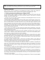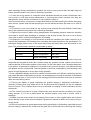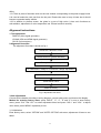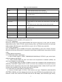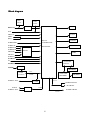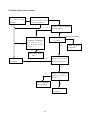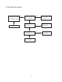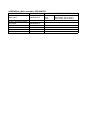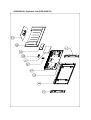
1
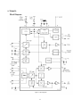
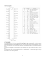
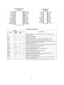
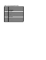
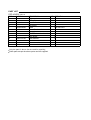
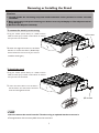
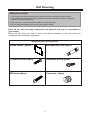
FILE NO. SERVICE MANUAL PDP-42XR7K PDP TV PRODUCT CODE No. 1 682 346 32: PAL/SECAM NTSC(AV) REFERENCE No.:SM0915051 CONTENTS Safety precautions………………………………………………………………………..… 1 Alignment instructions …………………………….…….………………………………… 3 Working principle analysis of the unit……………………………….………….………….6 Block diagram…………………………………..………………………………….…………7 IC block diagram………………………………………………………………………..……8 Wiring diagram ……………………………………………………………………………. 12 Troubleshooting guide ………………………………………………………………..…… 13 Schematic diagram………………………………………………………………………… 18 APPENDIX-A: Assembly list APPENDIX-B: Exploded view APPENDIX-C: Removing or installing the stand APPENDIX-D: Wall mounting Note: This maintenance manual is intended only for the reference of the maintenance people. Please pay attention to the following points before carrying out the maintenance work. Safety Precautions Please read the “Points for attention for the Maintenance & Repair of PDP” and “Criterion for Identifying the Defects on Screen” as below, before inspecting and adjusting the TV set. 1. “Points for attention for the Maintenance & Repair of PDP” To avoid possible danger, damage or jeopardy to health and to prevent PDP screen from new damage, the maintenance people must read the following carefully. If they ignore the following warnings, there will be deathful risks: 1.1 Screens vary from one model to another and therefore not interchangeable. Be sure to use the same type of screen in the replacement. 1.2 The operation voltage is approximately 350V for PDP module (including screen, driving circuit, logic circuit and power module). If you want to conduct maintenance work on PDP module when the set is in normal operation or just after the power is off, you must take proper measures to avoid electric shock and never have direct contact or touch with the circuitry of the working module or metal parts. That’s because within a short time relatively high voltage still remains on the capacitor of the driving part even after the power is off. Make sure to begin relevant maintenance operation at least one minute after the power is off. 1.3 Don’t apply on the module any power supply that is higher than the specification. If the power supply used deviates from the value given in the specification, there might be a possibility of leading to fire or damage to the module. 1.4 Never have operation or mounting work under unsuitable environment such as areas in the vicinity of water – bathroom, laundry, water chute of kitchen – sources of fire, heat-radiation parts or direct exposure to sunlight. Otherwise there will be kickbacks. 1.5 In case foreign substances such as water, liquid, metal slices or others fall into the module carelessly power must be cut off immediately. Keep the module as it is and do not move anything on the module. Otherwise it might be possible to contact the high voltage or cause shock short circuit so that it may lead to fire or electric shock. 1.6 If there is smoke, abnormal smell or sound from the module, please cut the power off immediately. Likewise in case the screen doesn’t work when the power is on or during the operation, please also cut off the power at once. No more operation in this case. 1.7 Do not remove or plug its connection wire when the module is in operation or right after the power is off. That’s because there remains a relatively high voltage on the capacitor of the driving circuit. If there is a need to remove or plug in the connection wire, please wait at least one minute after the power is off. 1.8 Considering the module has a glass faceplate, please avoid extrusion by external force lest it should cause glass breakage that may get people injured. Two people are needed in cooperation to move this module lest contingency takes place. 1.9 The complete TV set is designed on the basis of full consideration of thermal dissipation by convection, with the round hole on the top for heat emission. To avoid overheat, please do not have any covering on the hole during normal operation and never put it in the place where the space is narrow and in bad ventilation. 1.10 There is quite a number of circuits in PDP that are integrated ones. Please be on guard against 1 static electricity. During maintenance operation be sure to cover yourself with anti-static bag and before operation make sure to have it sufficiently grounded. 1.11 There are a big number of connection wires distributed around the screen. Please take care not to touch or scuff them during maintenance or removing the screen, because once they are damaged the screen will fail to work and it’s not possible to repair it. If the connection wires, connectors or components fixed by the thermotropic glue need to disengage when service, please soak the thermotropic glue into the alcohol and then pull them out in case of damage. 1.12 Connector for the circuit board of the screen part is relatively fine and delicate. Please take care in the replacement operation lest it should get damaged. 1.13 Special care must be taken during transportation and handling because strenuous vibration could lead to screen glass breakage or damage on the driving circuitry. Be sure to use a strong outer case to pack it up before transportation or handling. 1.14 Please put it for storage in an environment in which the conditions are under control so as to prevent the temperature and humidity from exceeding the scope stipulated in the specification. For prolonged storage please cover it with anti-moisture bag and have them piled and stored in one place. The environmental conditions are tabulated as below: Temperature Humidity Scope for operation 0~50centigrade Scope for storage -15~60centigrade Scope for operation 20%~80% Scope for storage 20%~80% 1.15 If a fixed picture is displayed for a long time, difference in its brightness and color may occur compared with movable pictures. But it doesn’t show any problem and the reason is that there is reduced density of fluorescent powder in the former. On the other hand, even if changes take place in the picture, it can keep its brightness for a period of time (several minutes). It’s a feature inherent with plasma and it’s not abnormal. However please try as much as possible to avoid showing a still picture of high brightness for a long time during operation. 1.16 As a digitalized display devise, this module is provided with error diffusion technology and the gray scale and false enhancement of contour can be displayed by reusing of sub-field. As compared with cathode ray tube, it can be found in the moving picture that at the brim of the face of a person there are some wrong colors. 1.17 During the display of graph (indicating the gradual change in brightness horizontally or vertically) resulting from gray scale test it can be found that the brightness for the two adjacent levels is uneven. This is caused by the reuse of sub-field, the display of load rectification and the electrolysis. 1.18 The screen front plate is of glass. Please make sure that the screen has been put in place during erection. If it is not in place before the erection begins it may lead to screen crack or breakage. 1.19 Make sure the screw used in the mounting of the screen is of the original specs lest it should cause damage to the screen due to mismatch. Special care should be taken not to use too long or too big screw. 1.20 Care must be taken to guard against dust during assembling or dismantling, especially to avoid dirt from falling in between the screen and the glass lest it should harm the receiving and viewing 2 effect. 1.21 There is piece of insulator stuck on the rear chassis corresponding to the power supply board. It is used to isolate the cool part from the hot part. Please take care to keep it intact lest it should become a potential safety trouble. 1.22 In addition to plasma screen, the glass is a part of high value. It has such functions as anti-radiation, adjustment of color temperature etc. Please handle it carefully. Alignment instructions 1. Test equipment PM5518 (video signal generator) VG-848 (VGA and HDMI signal generator) CA210 (color analyzer) 2 Alignment flow-chart The alignment flow-chart is shown as fig-1 Check DDC, HDCP KEY, FLASH Combined test for general assembly Factory initialization setup IF channel AFT voltage of TV and AGC voltage adjustment White balance adjustment Performance check Preset ex-factory Fig-1 adjustment flow-chart 3 Unit adjustments Connect all the boards according to wiring diagram, connect with power and observe the display. Method for entering factory menu: press “INPUT”, “2”, “5”, ”8” and “0” in turn to enter factory menu; press “CH+” and “CH-” to select adjustment items and press “VOL+” and “VOL-” to adjust value items, press “MENU” repeatedly to exit. 3.1 Initialization Enter factory menu, select “OPTION” and “HOTEL OPTION” sub-menu, adjustment of items to see table1. 3 Table1 sub-menu adjustment Items HOTEL Preset 0 Introduce 1: HOTEL OPTION of factory menu is optional 0: HOTEL OPTION of factory menu is not optional LOGO 1 1: display LOGO in no signal or turn on 0: no LOGO display ADC PRESCALE 00A adjust according the power consumption SIF PRESCALE 000 adjust according the power consumption BACK LIGHT 28 Adjust according the screen ALL COLOR 1 1: white balance of each channel auto offset based on the HDMI white balance 0: white balance of each channel adjust the offset base separately ISP 0 0: no upgrade on line 1: upgrade on line NO STANDY 00 01: turn on 00: memory function of turn on 10: standby INIT VOLUME 0-100 Volume when turn on INIT CHANNEL 1-200 Channel when turn on INIT SRC Program source Input Source when turn on EEPROM-MEMORAY > EEPROM Initialization (operate when EEPROM data chaos) RECALL 3.2 Adjustment for AFT and AGC of IF channel in TV 3.2.1 IF AFT adjustment Disconnect J601(B face), input 80dB 38.9MHz PAL signal to the pole of J601 near the socket, adjust L604 to value 1.65V of TP602, enter the factory menu, set TDA4470 from BG to LL and input 80dB 33.9MHz SECAM signal, adjust RP602 to value 1.65V of TP602, then weld J601. 3.2.2 IF AGC adjustment Input 184.25MHz RF signal of 60dB to RF terminal, adjust RP601 to value 4V of TP604, and there should be no obvious snowy picture. Increase the input signal to 90dBV and it should be no obvious noisy. 3.3 White balance adjustment 3.3.1 HDMI white balance adjustment a. Input VG-848 signal to HDMI: TIMING854(800*600/60Hz)of PAT920 8 gray scale signal, adjust the balance with CA210. b. Enter COLOR TEMP sub menu and select color temperature of standard (9300K), the value of coordinate is recommended. c. Fixed B GAIN, adjust R GAIN, G GAIN to let the color coordinate of the seventh level be (285,293); Fixed BOFF, adjust R OFF, G OFF to let the color coordinate of the second level be (285,293) and the brightness is about 3nit-10nit. Repeat adjust R GAIN, G GAIN, R OFF and G OFF, until the color coordinate of the two level gray scale be (285,293). 3.3.2 VGA/YPbPr/ AV white balance check and correct a. Connect VG-848 signal of VGA to VGA terminal and input TIMING854 (800*600/60HZ) (PATTERN: CROSS), and auto adjust to full screen then input PAT948 white and black signal, enter submenu of ADC ADJ, select AUTOTUNE and wait for OK display. Input PAT920(8 gray levels), 4 check if the white balance is normal, if not, set ALL COLOR to 0 and fine adjust according the method of 3.3.1 b. connect VG-848 YPbPr signal to YPbPr terminal and input TIMING972(1080I/60Hz) PAT908 color bar(include back/white bars), enter submenu of ADC ADJ, select AUTOTUNE and wait for OK display. Input PAT920(8 gray levels), check if the white balance is normal, if not, set ALL COLOR to 0 and fine adjust according the method of 3.3.2 c. Input AV signal(PM5518,8 gray scale) to VIDEO terminal and check if the white balance is normal, if not, set ALL COLOR to 0 and fine adjust according the method of 3.3.2. Note: it can’t set back to 1 once ALL COLOR changes to 0. 4. Software upgrading: Enter factory menu and select “OPTION”, set ISP to 1 and you can upgrade the software on line. After upgrade, it needs to set ISP back to 0. if it can not display the image during the upgrading, join J201 on main board, then perform the upgrading, when upgrade finish, disconnect J201 again. 5 Performance check 5.1 TV function Enter searching menu → auto search, connect RF-TV terminal with central signal source and check if the picture is normal, if there are channels be skipped. Check TXT and parental control function. 5.2 AV/S, YPbPr terminals Input AV/S, YPbPr / YCbCr HD signals, check if it is normal. 5.3 VGA terminal Insert VGA terminal, input VGA format signal of 640X480@60 Hz and check if the display is normal. 5.4 HDMI terminal Insert HDMI terminal, input 640X480@60Hz signal, check if the display is normal. Check HDCP function. 5.5 check sound channel Check the speaker and earphone of each channel. 5.6 RS232 terminal Insert the earphone wire to COM port, check the long-distance control function with special test software. 5.7 other function check Check the asleep timer, picture/sound mode, OSD, freeze/mute, stereo, etc. 5.8 presetting before ex-factory Item Setting Item Setting Item Setting PICTURE MODE STANDARD BALANCE 50 OSD LANGUAGE English COLOR MODE NORMAL VOLUME 50 OSD HPOSITION 50 AFC ON SLEEP TIMER OFF OSD VPOSITION 50 ZOOM FULL TTX LANGUAGE WEST OSD HALFTONE 50 SOUND MODE STANDARD OSD DURATION 15 AVC OFF 5 Working principle analysis of the unit The RF signal received by antenna will be sent to tuner TUN601, then IF signal will be obtained through high amplified and mixed frequency. After pre-intermediate amplified by V608, it will be sent to acoustic surface-wave Z605 to do IF filter and get better IF characteristics, then it will be sent to N602 (TDA4470) to do intermediate amplification, phase-lock loop VCO and synchronous wave detection to get the video signal TV-V; after pre-intermediate amplification IF will also be sent to acoustic surface-wave Z604 to do filter at the same time, the it will be sent to N404 to do intermediate amplification and output the second sound intermediate frequency signal TV-SIF. TV-V output from TDA4470 and TV-SIF will be sent to the main IC N304(MST9E89DL) Video and audio signals of AV/S, VGA, YPbPr will be sent to MST9E89DL too. 3 groups HDMI after PS321 selecting, their video and audio signal will be sent to MST9E89DL. RGB of SCART1, AV, S-Y and S-C of SCART2 will also be sent to MST9E89DL, their audio signal and YPbPr, AV/S audio signal via audio switch HEF4052BT selection to MST9E89DL. The main IC N304(MST9E89DL) is a high performance and fully integrated IC, which can realize HDMI interface processing, video decoding, video switch selection, A/D and D/A conversion, interlace/de-interlace processing, modes conversion, OSD and low-voltage differential output, etc. And it also has functions of audio selection, processing and MCU. The video signal via MST9E89DL processing, output 4 pairs differential signal and 1 pair clock signal for PDP panel display. TV-V from TDA4470 after video double amplifying and sent to SCART1 as AV-OUT. AV processed by MST9E89DL after quadruple amplifying and output as AV-OUT and SCART2 AV-OUT. The audio signal via MST9E89DL processing, it will be sent to N206 (BH3547F) amplifying to earphone. The audio signal will also sent to sound amplifier N203 (TPA3120-D2) amplifying to speaker. TV-L/R processed by MST9E89DL will be sent to SCART1 for AV-OUT, at the same time, TV-L/R and AV-L/R will output together as the audio output of AV-OUT and SCART2 AV-OUT. 6 Block diagram EDID EDID 24C02 24C02 PS321 HDMI 1/2/3 DDR VGA L/R-VGA FLASH YPbPr (DTV) PDP TV CONTROLLER SCART1-RGB EEPROM SCART1-AV SCART1-L/R AUDIO SW. SCART2-L/R HEF4052 HDCP KEY MST9E89DL L/R-YPbPr PANEL L/R-AV/S SCART2-Y SCART2-C AV AUDIO AMP. S-VIDEO BH3547F TUNER SAW EAR PHONE IF AMP TV-V TDA4470 TV-SIF AUDIO AMP. TPA3120D2 SPEAKER AV-L/R SCART1-V OUT TV-L/R 2*AMP SCART2-L/R OUT AV-L/R OUT AV OUT 4*AMP CVBS SCART2-V OUT SCART1-L/R OUT TV-L/R 7 IC block diagram 1. MST9E89DL The MST9E89DL is a high performance and fully integrated IC for multi-function LCD monitor/TV with resolutions up to full HD (1920x1080). It is configured with an integrated triple-ADC/PLL, an integrated DVI/HDCP/HDMI receiver, a multi-standard TV video and audio decoder, two video de-interlacers, two scaling engines, the MStarACE-3 color engine, an on-screen display controller, an 8-bit MCU and a built-in output panel interface. By use of external frame buffer, PIP/POP is provided for multimedia applications Furthermore, 3-Dvideo decoding and processing are fulfilled for high-quality TV applications. To further reduce system costs, the MST9E89DL also integrates intelligent power management control capability for green-mode requirements and spread-spectrum support for EMI management. 8 2. TDA4470 9 3. TPA3120D2 The TPA3120D2 is a 20-W (per channel) efficient, Class-D audio power amplifier for driving stereo single ended speakers or mono bridge tied load. The TPA3120D2 can drive stereo speakers as low as 4Ω. The efficiency of the TPA3120D2 eliminates the need for an external heat sink when playing music. The gain of the amplifier is controlled by two gain select pins. The gain selections are 20, 26, 32, 36 dB. The outputs are fully protected against shorts from GND to ROUT or LOUT and output-to-output shorts with an auto recovery feature. 10 11 Wiring diagram Power board LVDS output Speaker Main power Key board Panel Power board IR board Key, IR Tuner power Amplifier power Audio output SCART signal 12 SCART connection board SCART signal Main board Trouble shooting 1. Fault clearance Before servicing please check to find the possible causes of the troubles according to the table below. 1.1 Antenna (signal): Picture is out of focus or jumping Bad status in signal receiving Poor signal Check if there are failures with the electrical connector or the antenna. Check if the antenna is properly connected. Fringe in picture Check if the antenna is correctly oriented. Maybe there is electric wave reflected from hilltop or building. Picture is interfered by stripe shaped Possibly due to interference from automobile, train, high bright spots voltage transmission line, neon lamp etc. Maybe there is interference between antenna and power supply line. Please try to separate them in a longer distance. Maybe the shielded-layer of signal wire is not connected properly to the connector. There appear streaks or light color Check if interfered by other equipment and if interfered on the screen possibly by the equipment like transmitting antenna, non-professional radio station and cellular phone. 1.2 TV set: Symptoms Possible cause Unable to switch the power on Check to see if the power plug has been inserted properly into the socket. No picture and sound Check to see if the power supply of liquid crystal TV has been switched on. (As can be indicated by the red LED at the front of the TV set) See if it’s receiving the signal that is transmitted from other source than the station Check if it’s connected to the wrong terminal or if the input mode is correct. Check if the signal cable connection between video frequency source and the liquid crystal TV set is correct. Deterioration of color phase or color tone Check if all the picture setups have been corrected. Screen position or size is not proper Check is the screen position and size is correctly set up. Picture is twisted and deformed Check to see if the picture-frame ratio is properly set up. Picture color changed or colorless Check the “Component” or “RGB” settings of the liquid crystal TV set and make proper adjustment according to the 13 signal types. Picture too bright and there is distortion in the brightest area Check if the contrast setting is too high. Possibly the output quality of DVD broadcaster is set too high. It maybe also due to improper terminal connection of the video frequency signal in a certain position of the system. Picture is whitish or too bright in the darkest area of the picture Check if the setting for the brightness is too high Possibly the brightness grade of DVD player (broadcaster) is set too high. No picture or signal produced from the displayer if “XXX in search” appears. Check if the cable is disconnected. Check if it’s connected to the proper terminal or if the input mode is correct. There appears an indication “outside the receivable scope) Check if the TV set can receive input signal. The signal is not correctly identified and VGA format is beyond the specified scope. Remote control cannot work properly Check if the batteries are installed in the reverse order. Check if the battery is effective. Check the distance or angle from the monitor. Check if there is any obstruct between the remote control and the TV set. Check if the remote control signal- receiving window is exposed to strong fluorescence. No picture and sound, but only hash. Check if the antenna cable is correctly connected, or if it has received the video signal correctly. Blur picture Check if the antenna cable is correctly connected. Of if it has received the right video signal. No sound Check if the “mute” audio frequency setting is selected. Check if the sound volume is set to minimum. Make sure the earphone is not connected. Check if the cable connection is loose. When playing VHS picture search tape, there are lines at the top or bottom of the picture. When being played or in pause VHS picture search tape sometimes can’t provide stable picture, which may lead to incorrect display of the liquid crystal TV, In this case please press “auto” key on the remote control so as to enable the liquid crystal TV set to recheck the signal and then to display correct picture signal 14 2. Troubleshooting guide 2.1. No raster Connect the power, check if the red indicator is light in STANDBY? yes no Check if X403 PIN9 (5V) of main board is normal? Press POWER button on the unit or remote controller and check the indicator. red blue no Check if the PIN3 of X401 on main board is high-level? Check STANDBY circuit of power supply board yes Check the panel, LVDS wires or the wires connect panel and power. no no Check N304 and its periphery Check if the PIN11 of X403 in main board is high-level? yes Check N304 and its periphery 15 Check power supply board 2.2. Have raster, but no picture Check if the unit button and remote control operation? no Does display OSD menu in screen when press menu button? yes no yes yes Check if the all channels have no signal? no no Enter factory-menu, initialization EEPROM, then turn off the TV, turn on again, display picture? Which channel is no signal? HDMI/VGA/YPRPB TV yes Adjust main board again Check N304 and its periphery yes Check if there is 1VPP signal or noisy of X405 TP601 on main board? no no Check TUNER601 and its periphery Check if TUNER601 (pin11) IF output is normal? yes Check N602 and its periphery 16 Check N304 and its periphery 2.3. No sound (TV channel) Check if the voltage of N203 pin1, 3, 10, 12, 19, 20 are normal yes Check the wave of pin 5, 6 of N203 yes Check N203 and its periphery no no Check power board Check the wave of N602 pin 24 yes Check N304 and its periphery no Check the wave of TUNER601 pin 11 no Check TUNER601 and its periphery 17 yes Check N602 and its periphery APPENDIX-A: Main assembly PDP-42XR7K NAME NO. Main board XI6HK0300110 SCART connection board Key board Power filter board Power board Remote control Panel XI6HK0304610 XI6HK0300510 XI6FK0105110 XI6HU0522010 XI6010Y06006 XI5205422206 MAIN COMPONENT AND IT'S NO. N304 N602 N203 RC-Y60-0F PDP42G1 MST9E89DL (5270989005) TDK4470MFL (5274470001) TPA3120-D2 (5273120001) APPENDIX-B: Exploded view (PDP-42XR7K) PART LIST OF EXPLODED VIEW NO. 1 2 3 4 5 6 7 8 9 10 11 12 13 DESCRIPTION Right speaker Left speaker Front cabinet Key board Panel Power filter board Power board SCART connection board Main board Back cabinet Stand User manual Remote Control PART LIST PDP-42XR7K ver.1.0 REF.No. PARTS No. 1 XI6170741000 2 XI6170740000 3 XI5QI06R401A 4 XI6HK0300510 5 XI5205422206 6 XI6FK0105110 7 XI6HU0522010 8 XI6HK0304610 9 XI6HK0300110 10 XI5HI31LJ01B 11 XI6151062500 12 XI5944034370 13 XI6010Y06006 DESCRIPION Right speaker Left speaker Front cabinet Key board Panel Power filter board Power board SCART connection board Main board Back cabinet Stand User manual Remote control Only the parts in above list are used for repairing. Other parts except the above parts can't be supplied. Q'TY REMARK 1 1 1 1 1 LG PDP42G1 1 1 1 1 1 1 1 1 Removing or Installing the Stand Cautions: 1. Carefully handle the unit during setup and consult authorized service personnel to ensure successful installation. 2. Before performing work spread cushioning over the base area to lay the Display on. This will prevent it from being damaged. 3. Disconnect the AC power cord firstly. To remove the stand: (if wall mounting) 1.Lay your TV flat (screen down) on a table or bench. M5 screws Make sure that you put down a soft cushion or cloth so that your TV is not scratched. 2.Loosen the eight M5 screws on the Stand bottom to remove the Stand. (Please keep these screws for future use if you want to install the stand again.) To install the stand 1.Lay your TV flat (screen down) on a table or bench. Make sure that you put down a soft cushion or cloth so that your TV is not scratched. 2. Insert the stand column into the hole in the TV bottom, and then secure the stand to the TV with eight M5 screws. M5 screws Note ! Do not remove the stand from the TV unless using an optional bracket to mount it. ! The appearance of the unit may differ from the actual one. Note 1 Wall Mounting Safety Precautions: 1.Thoroughly read this instruction before setup and follow the steps below precisely. 2.Very carefully handle the unit during setup and consult authorized service personnel to ensure successful installation. 3.The wall to be mounted should be made from solid materials. 4.Do not uplift the speaker when moving the plasma display. Note: all the wall mounting components are optional and may be unavailable in your model. Below we will show you how to mount the plasma display on the wall using our company’s wall mounting components. Identifying the Following Parts Frame holder (1piece ) M8 Expansion bolt (4pcs) T4 Wood screw (24pcs) Combined Screw (4pcs) M4 Screw (2pcs) Connector (4pcs) 2 Wall Mounting (continued) Mount the Frame Holder On the Wall Mount on the concrete wall 1.Insert and screw 2pcs M4 screws on each side of the holder (Refer to mark in Fig.1) and the depth is about 8mm. 1 1 2. Fix the Frame Holder on the wall with 4pcs M8 expansion bolts and confirm they are securely fixed and reliable.(refer to mark in Fig.1) 2 1 3. Make sure that when the max. load to the Frame Holder is larger than 1500 Newton, the Holder should not fall down and the wall should not be broken. 2 1 Fig.1 Mount on a wooden structure 1.Insert and screw 2pcs M4 screws on each side of the holder (Refer to mark in Fig.2) and the depth is about 8mm. 2. Fix the Frame Holder on the wall with at least 16pcs T4 wood screws and confirm they are securely fixed and reliable.(refer to mark in Fig.2) 1 1 2 1 1 3. Make sure that when the max. load to the Frame Holder is larger than 1500 Newton, the Holder should not fall down and the wall should not be broken. 3 2 Fig.2 Wall Mounting (continued) Remove the Screws Remove the 4pcs M8 screws on the rear of the display. Mounting the Connectors 1. Mount 4pcs connectors to the four Combined screw corners of the rear of the plasma Connector display with 4pcs Combined screws. CAUTIONS: The direction of the Connectors should be strictly conform to the diagram illustrated. 4 Wall Mounting (continued) Mount the display to the Frame Holder a. Put the unit close to the wall Frame Holder, aiming the four wall mounting connectors to the four calabash-shaping holes. Insert the wall mounting connectors into the calabash-shaping holes, let the unit slowly slide down to the end of the calabash-shaping holes and be sure the mounting is secure. b. Tightly screw the left and right M4 screws marked withƒ to prevent the display from falling from the Frame Holder. 1 2 5 Dec/2008