1
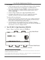
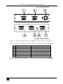
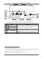
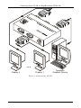
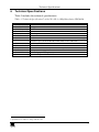
Kramer Electronics, Ltd.
USER MANUAL
Model:
VP-450
1:4 High Resolution UXGA DA
Contents
Contents
1
2
3
4
5
6
Introduction
Getting Started
Overview
Your VP-450 1:4 High Resolution UXGA DA
Connecting Your VP-450 1:4 High Resolution UXGA DA
Technical Specifications
1
1
1
2
5
7
Figures
Figure 1: VP-450 1:4 High Resolution UXGA DA
Figure 2: VP-450 1:4 High Resolution UXGA DA – Top and Lower Side Panels
Figure 3: VP-450 1:4 High Resolution UXGA DA Underside
Figure 4: Connecting the VP-450
2
3
4
6
Tables
Table 1: Features and Functions of the VP-450 1:4 High Resolution UXGA DA
Table 2: VP-450 1:4 High Resolution UXGA DA Underside Features
Table 3: Technical Specifications of the VP-450 1:4 High Resolution UXGA DA
3
4
7
i
Introduction
1
Introduction
Welcome to Kramer Electronics (since 1981): a world of unique, creative and
affordable solutions to the infinite range of problems that confront the video, audio
and presentation professional on a daily basis. In recent years, we have redesigned
and upgraded most of our line, making the best even better! Our 350-plus different
models now appear in 8 Groups1, which are clearly defined by function.
Congratulations on purchasing your Kramer TOOLS VP-450 1:4 High
Resolution UXGA DA which is ideal for:
Multi monitor applications or presentation systems requiring local
monitors and large screen display devices such as a projector
Rental and staging systems
Schools, churches, corporate applications
The package includes the following items:
VP-450 1:4 High Resolution UXGA DA
Power adapter (12V DC Input)
This user manual2
2
Getting Started
We recommend that you:
Unpack the equipment carefully and save the original box and packaging
materials for possible future shipment
Review the contents of this user manual
Use Kramer high performance high resolution cables3
3
Overview
The Kramer VP-450 is a high performance 1:4 distribution amplifier for
UXGA and higher resolution signals.
1 GROUP 1: Distribution Amplifiers; GROUP 2: Video and Audio Switchers, Matrix Switchers and Controllers; GROUP 3:
Video, Audio, VGA/XGA Processors; GROUP 4: Interfaces and Sync Processors; GROUP 5: Twisted Pair Interfaces;
GROUP 6: Accessories and Rack Adapters; GROUP 7: Scan Converters and Scalers; and GROUP 8: Cables and Connectors
2 Download up-to-date Kramer user manuals from our Web site: http://www.kramerelectronics.com
3 The complete list of Kramer cables is on our Web site at http://www.kramerelectronics.com
1
Your VP-450 1:4 High Resolution UXGA DA
The VP-450:
Accepts one input, provides correct buffering and isolation, and then distributes
the signal to 4 identical outputs on high-density 15-pin HD connectors
Has a video bandwidth exceeding 400MHz, ensuring that the machine
remains transparent even at high-resolution graphics modes such as
UXGA (1600x1200)
Accepts analog or digital syncs1 and provides ID Bit control2
Can output video signals that are DC or AC coupled for maximum
flexibility (selected via red, green and blue coupling buttons)
To achieve the best performance:
Connect only good quality connection cables, thus avoiding interference,
deterioration in signal quality due to poor matching, and elevated noise
levels (often associated with low quality cables)
Avoid interference from neighboring electrical appliances that may
adversely influence signal quality and position your Kramer VP-450 away
from moisture, excessive sunlight and dust
4
Your VP-450 1:4 High Resolution UXGA DA
Figure 1, Figure 2 and Table 1 define the VP-450 unit:
Top Side Panel
Lower Side Panel
Figure 1: VP-450 1:4 High Resolution UXGA DA
1 The polarity is determined via a pair of underside switches. Note that both the Hs (horizontal sync) switch and the Vs
(vertical sync) switch should be set identically
2 Via an underside switch. Sometimes notebook computers refuse to output a VGA signal to an external VGA monitor. By
setting the ID BIT to ON, the notebook will output to an external VGA monitor
2
KRAMER: SIMPLE CREATIVE TECHNOLOGY
Your VP-450 1:4 High Resolution UXGA DA
Top Side Panel
Lower Side Panel
Figure 2: VP-450 1:4 High Resolution UXGA DA – Top and Lower Side Panels
Table 1: Features and Functions of the VP-450 1:4 High Resolution UXGA DA
#
1
2
3
4
5
6
7
Feature
OUTPUT 2 HD15F Connector
OUTPUT 1 HD15F Connector
12V DC
INPUT HD15F Connector
OUTPUT 3 HD15F Connector
ON LED
OUTPUT 4 HD15F Connector
Function
Connect to the UXGA acceptor 2
Connect to the UXGA acceptor 1
+12V DC connector for powering the unit
Connect to the UXGA source
Connect to the UXGA acceptor 3
Illuminates when receiving power
Connect to the UXGA acceptor 4
Figure 3 and Table 2 define the switches on the underside of the VP-450:
3
Your VP-450 1:4 High Resolution UXGA DA
Figure 3: VP-450 1:4 High Resolution UXGA DA Underside
Table 2: VP-450 1:4 High Resolution UXGA DA Underside Features
2
3
COUPLING
#
1
Feature
BLUE DC-AC Switch
GREEN DC-AC Switch
Function
Switch to DC to select DC coupling1, switch to AC to select AC
coupling (removing the DC offset of the input signal)
RED DC-AC Switch
4
5
Hs (Horizontal Sync) Switch
Vs (Vertical Sync) Switch
6
ID Bit Switch
Set both switches2 to Hi-Z (TTL3) if the source is, for example, a
digital graphics card. Set both switches to 75 (ANALOG) if the
source is analog based, for example, an RGBHV source with coaxial
cable for sync
Slide to the left to set to ON4; to the right to set to OFF
1 Achieving the best linearity and signal fidelity
2 Both the Hs and the Vs switches should be set identically – since graphics cards do not have mixed (TTL and ANALOG)
syncs. (No harm will occur to the graphics source if the switches are set to the wrong direction)
3 “Transistor-Transistor Logic” for syncs with digital logic levels
4 Enabling the notebook or laptop to output a VGA signal to an external VGA monitor
4
KRAMER: SIMPLE CREATIVE TECHNOLOGY
Connecting Your VP-450 1:4 High Resolution UXGA DA
5
Connecting Your VP-450 1:4 High Resolution UXGA DA
To output a UXGA1 signal from a computer graphics card to 4 monitors, as the
example in Figure 4 illustrates, do the following:
1. Connect a UXGA1 source (for example, a computer graphics card) to the
INPUT HD15F connector.
2. Connect the OUTPUT HD15F connectors to up to 4 acceptors, as follows:
Connect the OUTPUT 1 connector to an acceptor (for example,
Display 1)
Connect the OUTPUT 2 connector to an acceptor (for example,
Display 2)
Connect the OUTPUT 3 connector to an acceptor (for example,
Display 3)
Connect the OUTPUT 4 connector to an acceptor (for example,
Display 4)
3. On the underside of the VP-450:
Set both the Hs and Vs switches to Hi-Z (TTL)
Slide the ID Bit switch to the left to set to ON
Set the RED, BLUE and GREEN COUPLING switches either to DC
or AC, according to the output requirements
4. Connect the 12V DC power adapter to the power socket and connect the
adapter to the mains electricity.
1 Or any resolution, such as VGA, SVGA, XGA, and so on
5
Connecting Your VP-450 1:4 High Resolution UXGA DA
Display 4
Computer
Graphics Source
Display 1
Figure 4: Connecting the VP-450
6
KRAMER: SIMPLE CREATIVE TECHNOLOGY
Technical Specifications
6
Technical Specifications
Table 3 includes the technical specifications:
1
Table 3: Technical Specifications of the VP-450 1:4 High Resolution UXGA DA
INPUT:
OUTPUTS:
MAX. OUTPUT LEVEL:
BANDWIDTH (-3dB):
DIFF. GAIN:
DIFF. PHASE:
K-FACTOR:
S/N RATIO:
CONTROLS:
COUPLING:
POWER SOURCE:
DIMENSIONS:
WEIGHT:
ACCESSORIES:
OPTIONS:
1 XGA on an HD15F connector
4 XGA on HD15F connectors
2.3Vpp
420MHz
0.04%
0.03 Deg.
<0.05%
81dB
AC/DC selectors for R, G, B via 3 switches; Pair of switches for analog/TTL
selection syncs on the underside; ID Bit switch on the underside
DC/AC by selection
12VDC, 125mA
12cm x 7.15cm x 2.76cm (4.7" x 2.8" x 1.08"), W, D, H
0.3 kg. (0.67 lbs.) approx.
Power supply, mounting bracket
19" rack adapters RK-T1, RK-T3
1 Specifications are subject to change without notice
7
LIMITED WARRANTY
Kramer Electronics (hereafter Kramer) warrants this product free from defects in material and workmanship under the
following terms.
HOW LONG IS THE WARRANTY
Labor and parts are warranted for seven years from the date of the first customer purchase.
WHO IS PROTECTED?
Only the first purchase customer may enforce this warranty.
WHAT IS COVERED AND WHAT IS NOT COVERED
Except as below, this warranty covers all defects in material or workmanship in this product. The following are not covered
by the warranty:
1.
2.
3.
Any product which is not distributed by Kramer, or which is not purchased from an authorized Kramer dealer. If you are
uncertain as to whether a dealer is authorized, please contact Kramer at one of the agents listed in the web site
www.kramerelectronics.com.
Any product, on which the serial number has been defaced, modified or removed.
Damage, deterioration or malfunction resulting from:
i)
Accident, misuse, abuse, neglect, fire, water, lightning or other acts of nature
ii)
Product modification, or failure to follow instructions supplied with the product
iii)
Repair or attempted repair by anyone not authorized by Kramer
iv)
Any shipment of the product (claims must be presented to the carrier)
v)
Removal or installation of the product
vi)
Any other cause, which does not relate to a product defect
vii)
Cartons, equipment enclosures, cables or accessories used in conjunction with the product
WHAT WE WILL PAY FOR AND WHAT WE WILL NOT PAY FOR
We will pay labor and material expenses for covered items. We will not pay for the following:
1.
2.
3.
Removal or installations charges.
Costs of initial technical adjustments (set-up), including adjustment of user controls or programming. These costs are the
responsibility of the Kramer dealer from whom the product was purchased.
Shipping charges.
HOW YOU CAN GET WARRANTY SERVICE
1.
2.
3.
To obtain service on you product, you must take or ship it prepaid to any authorized Kramer service center.
Whenever warranty service is required, the original dated invoice (or a copy) must be presented as proof of warranty coverage,
and should be included in any shipment of the product. Please also include in any mailing a contact name, company, address, and
a description of the problem(s).
For the name of the nearest Kramer authorized service center, consult your authorized dealer.
LIMITATION OF IMPLIED WARRANTIES
All implied warranties, including warranties of merchantability and fitness for a particular purpose, are limited in duration to
the length of this warranty.
EXCLUSION OF DAMAGES
The liability of Kramer for any effective products is limited to the repair or replacement of the product at our option. Kramer
shall not be liable for:
1.
2.
Damage to other property caused by defects in this product, damages based upon inconvenience, loss of use of the product, loss
of time, commercial loss; or:
Any other damages, whether incidental, consequential or otherwise. Some countries may not allow limitations on how long an
implied warranty lasts and/or do not allow the exclusion or limitation of incidental or consequential damages, so the above
limitations and exclusions may not apply to you.
This warranty gives you specific legal rights, and you may also have other rights, which vary from place to place.
NOTE: All products returned to Kramer for service must have prior approval. This may be obtained from your dealer.
This equipment has been tested to determine compliance with the requirements of:
EN-50081:
"Electromagnetic compatibility (EMC);
generic emission standard.
Part 1: Residential, commercial and light industry"
EN-50082:
"Electromagnetic compatibility (EMC) generic immunity standard.
Part 1: Residential, commercial and light industry environment".
CFR-47:
FCC Rules and Regulations:
Part 15: “Radio frequency devices
Subpart B – Unintentional radiators”
CAUTION!
Servicing the machines can only be done by an authorized Kramer technician. Any user who makes changes or modifications to
the unit without the expressed approval of the manufacturer will void user authority to operate the equipment.
Use the supplied DC power supply to feed power to the machine.
Please use recommended interconnection cables to connect the machine to other components.
8
KRAMER: SIMPLE CREATIVE TECHNOLOGY
For the latest information on our products and a list of Kramer
distributors, visit our Web site: www.kramerelectronics.com,
where updates to this user manual may be found.
We welcome your questions, comments and feedback.
Safety Warning:
Disconnect the unit from the power supply before
opening/servicing.
Caution
Kramer Electronics, Ltd.
Web site: www.kramerelectronics.com
E-mail: [email protected]
P/N: 2900-000123 REV 2