1
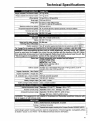
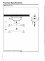
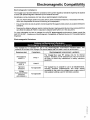
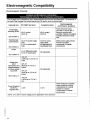
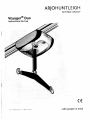
ARJOHUNTLEIGH
GETINGE GROUP
Voyager® Duo
Instructions for Use
IE *
001.19520.EN rev. 5 • M a r c h 2012
Wjam
.with people in mind
Design Policy and Copyright
® and ™ are trademarks belonging to the ArjoHuntleigh group of companies.
©ArjoHuntleigh 2011.
As our policy is one of continuos improvement, we reserve the right to modify designs without prior notice.
The content of this publication may not be copied either whole or in part without the consent of
ArjoHuntleigh.
Table of Contents
G e n e r a l Information
Foreword
Service and support
Manufacturer Information
Definitions U s e d in this M a n u a l :
Intended Use
O p e r a t i o n a l Life
E q u i p m e n t Identification
Verifying the Package Contents
H o w to Use this M a n u a l
Symbols Used
Safety Instructions
G e n e r a l Instructions
A d d e n d u m for Rail S y s t e m O t h e r t h a n K W I K t r a k
Safe Working Load
I m p o r t a n t S a f e t y Directions
Shock Prevention
Fire a n d E x p l o s i o n P r e v e n t i o n
H u m a n and Environmental Safety Practices
B a t t e r y a n d Battery C h a r g e r S a f e t y P r a c t i c e s
Equipment Warning Labels
Part Designation
V o y a g e r D u o C e i l i n g Lift a n d C h a r g e r S t a t i o n for K W I K t r a k Rail S y s t e m
Hand Control
Chargers
Slings
Compatible Slings
H o w to u s e t h e V o y a g e r D u o C e i l i n g Lift
Return to Charge (RTC)
E m e r g e n c y S t o p (red c o r d )
Emergency Lowering
Emergency Brake
Battery Information
Indicator L i g h t s
Charging the Batteries
Using the FIDO Function (Pre-Programmed Positions)
U s e of S l i n g s
Spreader Bars and Stretcher Frame
Slings
Before Approaching the Patient
P r o c e d u r e for U s i n g L o o p S l i n g s w i t h a T w o - P o i n t S p r e a d e r B a r
T o Lift a P a t i e n t f r o m a B e d
T o Lift a P a t i e n t f r o m a C h a i r
T o Lift a P a t i e n t f r o m t h e Floor
Before Transferring a Patient
Using Stretcher Frames and Stretchers
Voyager Duo Programming
C h a n g i n g t h e S p e e d of M o v e m e n t
A d j u s t i n g t h e S p r e a d e r Bar H e i g h t
E n a b l e / D i s a b l e R e t u r n to C h a r g e ( R T C )
Care and Maintenance
Preventive Maintenance Schedule
5
5
5
6
6
6
6
6
7
7
8
9
9
9
10
10
10
11
11
11
11
12
12
13
-13
............14
-14
15
15
16
16
-18
18
18
18
20
20
20
20
20
20
22
22
23
23
23
24
24
25
26
•
27
27
3
Table of Contents
User Inspections
:
Inspections by an Authorized Service Technician
Daily Checklist
Inspection and Cleaning
Strap Inspection
Handling and Storage
Batteries Replacement
Verification of the Charger's Power Source
Sling Inspection and Care
Regular Inspections
Sling Laundering
Annual Inspection
Maintenance Requirements
Troubleshooting
Labels o n the Lift
Technical Specifications
Lift Dimensions
Electromagnetic Compatibility
Electromagnetic Compliance
Electromagnetic Emissions
Electromagnetic Immunity
27
28
30
30
30
30
31
31
31
31
31
31
31
....32
..............34
35
36
37
37
37
38
General Information
T h a n k y o u for p u r c h a s i n g
the Voyager Duo ceiling lift
from ArjoHuntleigh.
Your Voyager Duo is part
of a series of quality
products
designed
specially for home care,
nursing h o m e s and other
health care u s e s .
We
are
dedicated
to
serving your needs and
providing
the
best
products available along
with training that will bring
your
staff
maximum
benefit
from
every
ArjoHuntleigh product.
P l e a s e read this manual
thoroughly, and contact u s
if y o u have any questions
about the operation or
maintenance
of
your
ArjoHuntleigh equipment.
Foreword
Please read this manual in its entirety before using your
Voyager Duo. The information in this manual is crucial to the
proper operation and maintenance of the equipment, and will
help protect your product as well as ensure that the
equipment performs to your satisfaction. Lifting and
transferring a person always presents a potential risk. Some
of the information in this manual is important for your safety
and must be read and understood to help prevent injuries.
ArjoHuntleigh strongly advises and warns that to avoid
injuries that can be attributed to the use of inadequate parts,
only parts designated by ArjoHuntleigh should be used on
equipment and other appliances supplied by ArjoHuntleigh.
Furthermore,
unauthorized
modifications
on
any
ArjoHuntleigh equipment may affect its safety. ArjoHuntleigh
will not be held responsible for any accidents, incidents or
deficiencies of performance that occur as a result of any
unauthorized modification to its products.
Tested according to standards by:
TUV Product Service and ( f t .
Service and support
A service routine must be performed on your Voyager Duo by
ArjoHuntleigh certified service personnel. This will ensure the
safety and good functioning of your product. See section
called "Care and Maintenance" in this manual.
If you require further information, please contact your local
ArjoHuntleigh representative which can offer comprehensive
support and service programs to maximize the long-term
reliability, safety and value of the product. Contact your local
ArjoHuntheigh representative for replacement parts.
Additional copies of this manual can be purchased from your
local ArjoHuntleigh representative. When ordering, include
the Instructions for Use product number (see front page) and
equipment identification number.
General Information
M a n u f a c t u r e r Information
This product has been manufactured by:
ArjoHuntleigh A B
VerkstadsvSgen 5
241 3 8 Esidv
SWEDEN
D e f i n i t i o n s U s e d in t h i s M a n u a l :
Years
Transfers per Day
(10,000 transfers)
4
7
6
4.5
8
3.5
Fig. 1
WARNING:
M e a n s : Failure to understand and follow these
instructions may result in injury to yourself
a n d others.
CAUTION:
M e a n s : Failure to follow t h e s e instructions
may c a u s e damage to the product.
NOTE:
Means*
This
is
important
information
regarding the correct u s e of the equipment.
Intended U s e
The Voyager Duo is designed for lifting patients in
a homecare setting, at nursing homes and other
assisted living centers. Patient transferring is
performed
under
the
supervision
of
an
appropriately
trained
caregiver
staff
in
accordance with the instructions outlined in this
manual. All other uses must be avoided.
The equipment must only be used for the
purposes stated above, and must be installed by
ArjoHuntleigh authorized personnel and in
accordance with local codes.
Operational Life
The equipment is designed and tested for a
useful life of seven (7) years or 10,000
transfers—whichever comes first—subject to
preventative maintenance as specified in the
"Care and Maintenance" section in this manual.
Time equivalence between the number of
transfers versus the number of years is made
clear in the table in Fig. 1.
6
WARNING: The manufacturer cannot e n s u r e
full safety for a ceiling lift or an a c c e s s o r y of
which the life s p a n h a s been e x c e e d e d .
The red indicator light on the ceiling lift will blink
when it is about halfway to its useful life, and
again to indicate the end of the useful life period.
The operating life of this equipment corresponds
directly to the safe operating time period before a
complete overhaul is required. Aging of the
cassette, frequency of use (transfers per day), the
weight of the patient and maintenance frequency
are factors that have an impact on the
Voyager Duo's life span. A transfer is defined as
the displacement of a patient from one point to
another. A transfer cycle includes a lifting and a
descending action.
The expected operational life for fabric slings and
fabric stretchers is approximately two years from
date of purchase. This life expectancy only
applies if the slings and stretchers have been
cleaned, maintained and inspected in accordance
with the ArjoHuntleigh Sling Application Guide,
the Instructions
for Use and the "Preventive
Maintenance Schedule".
The expected life for other consumable products,
such as batteries, fuses, lamps, slings, straps and
cords is dependent upon the care and usage of
the equipment concerned. Consumables must be
maintained
in
accordance
with
published
Instructions
for
Use
and the
"Preventive
Maintenance Schedule".
E q u i p m e n t Identification
The unit's identification number (specification,
model, serial number) appears on a silver
nameplate attached to the lift's plastic housing.
General Information
V e r i f y i n g the P a c k a g e C o n t e n t s
Always ensure that the ceiling lift will be installed
by a contractor or installer that has been
authorized by ArjoHuntleigh.
Upon receipt of the equipment, verify it against
the packing list to ensure it is complete and
inspect the equipment for possible damage due to
shipping. If there is any damage, notify the carrier
immediately to file a claim. Provide complete
information concerning
damage
claims
or
shipping errors to your local ArjoHuntleigh
representative.
Include
all
equipment
identification numbers and group part numbers (if
any) as described above along with a full
description of damaged parts.
H o w to U s e t h i s M a n u a l
WARNING: Do not attempt to u s e this
equipment without fully understanding the
information contained in this manual.
To ensure the safe operation of the Voyager Duo,
read the entire manual carefully, especially the
"Safety Instructions" section, before installing,
operating, or servicing this equipment.
If anything is not completely understood, please
contact your local ArjoHuntleigh representative
for more details. Failure to comply with warnings
in this manual may result in injuries.
Keep this manual with the lift and refer to it as
required. Make sure that all operators are
regularly trained in the use of the equipment
according to the information found therein.
>
z
UJ
o
7
General Information
Symbols Used
Key to s y m b o l s
Symbol
This symbol is accompanied by a date to indicate the date of manufacture
and by the address of the manufacturer.
J
This symbol indicates the products comply with the medical device directive
93/42/EEC.
©•
c
This symbol indicates the approval of the Canadian Standards Association.
us
REF
SN
This symbol is accompanied by the manufacturer's catalogue number.
This symbol is accompanied by the manufacturer's serial number.
This symbol indicates "separate collection"
accumulators as per the W E E E Directive.
This symbol refers to the Instructions
1 1
for
all
batteries
for Use.
This symbol indicates a class II electrical equipment: term referring to
electrical equipment in which protection against electric shock does not rely
on basic insulation only.
•
ft
This symbol indicates a type BF applied part.
This symbol indicates a risk of pinching.
©
This symbol locates the emergency stop system on the lift.
This symbol locates the emergency lowering system on the lift.
Fig. 2
8
and
Safety Instructions
The equipment must be used
in a c c o r d a n c e with these
safety instructions.
Anyone using the equipment
must also have read and
understood the instructions
in this manual.
General Instructions
Keep these Safety Instructions with the ceiling lift at all
times.
Read the Instructions
for Use in this manual
installing, operating, or servicing this equipment.
before
WARNING: T h e Voyager Duo is for transferring
patients only. Do not u s e the lift for any other
purpose.
If there is anything y o u are
not sure about, contact your
local
ArjoHuntleigh
representative.
WARNING: A l w a y s place the sling around the patient
according to the instructions e n c l o s e d . Failure to do
s o may result in injuries to y o u or to others.
C A U T I O N : Do not drop either the ceiling lift c a s s e t t e
or the batteries, s i n c e they may c a u s e internal
damage that is not easily s e e n . If the ceiling lift i s
s u s p e c t e d to be damaged, contact your local
ArjoHuntleigh representative for servicing.
NOTE: ArjoHuntleigh ceiling lifts are specifically
designed for KWIKtrak rail s y s t e m s , ArjoHuntleigh
slings a n d a c c e s s o r i e s .
A d d e n d u m for R a i l S y s t e m O t h e r t h a n K W I K t r a k
ArjoHuntleigh could have adapted this ceiling lift to be used
with a rail system other than KWIKtrak.
If this is the case, an addendum (001-14250-**)* must be
supplied with this Instructions for Use, please refer to the
addendum for informations relevant to that specific rail
system.
The addendum provides important informations relative to:
•
Safe Working Load
•
Rail System Limitations
•
description for specific parts.
Before using the Voyager Duo, make sure it is compatible
with accessories installed on that rail system.
WARNING: Before using the Voyager Duo on a rail
s y s t e m other than KWIKtrak, make s u r e you have
read and understood the addendum supplied with
this Instructions for Use.
*. Last two characters varies according to the manual language.
Safety Instructions
Safe W o r k i n g Load
•
The Voyager Duo for KWIKtrak rail system has
been designed with two settings with regards to
the safe working load:
The spreader bar being used is intended to be
used with the Voyager Duo and is capable of
bearing the patient's weight.
•
The sling is intended to be used for this lift and
can take the weight of the patient.
•
The sling is not damaged, torn or frayed.
•
The lifting procedures outlined in this manual
are followed.
•
All controls and safety features are used only
according to the rules specified in this manual.
Never attempt to force a control or button on
the lift.
•
The charger is not stored in a shower, bath or
other areas with high humidity.
•
The sling straps are in good condition and
properly fastened.
•
The daily maintenance is earned out before
using the lift.
•
Any precautionary or instruction labels that
cannot be easily read are replaced.
•
100 kg (220 lb): Safe working load
•
200 kg (440 lb): Maximum capacity of the lift
adjusted in factory
This setting has already been determined by the
ArjoHuntleigh installation team in accordance with
the load bearing capabilities of your installation.
W A R N I N G : Refer t o t h e a d d e n d u m f o r rail
system other than KWIKtrak.
WARNING: T h e Voyager Duo is intended to
be u s e d for patients w h o s e weight is within
a specified safe working load. Do not
attempt to lift more than the lowest weight
limit indicated on the following:
•
the rail s y s t e m ;
•
the "maximum load" label on the
Voyager Duo;
•
on the spreader bar;
•
on the a c c e s s o r i e s ;
•
on the sling.
WARNING: Before using the Voyager Duo, a
clinical
assessment
of
the
patient's
suitability for transfer must be carried out by
a qualified health professional considering
that, among other things, the transfer may
induce substantial p r e s s u r e on the patient's
body.
WARNING: T h e Voyager Duo h a s a safe
working load, adjusted in factory, of 200 kg
(440 lb) which is the maximum load of the lift.
C A U T I O N : K e e p all components of the lift
clean and dry, and have electrical and
mechanical
safety
checks
done
as
instructed in the " C a r e and Maintenance"
section of this manual.
In the event that the Voyager Duo needs to
be installed on a rail s y s t e m that does not
support more than 100 kg (220 lb), the safe
working load c a n be adjusted to 100 kg
(220 lb) by removing a special key from the
lift. T h i s key must be removed by a qualified
technician.
Important Safety Directions
Always ensure that:
•
The ceiling lift is installed by an authorized
ArjoHuntleigh contractor or installer.
•
The equipment is used by trained staff.
•
The rail installation will accept a load equal or
higher to that of the ceiling lift.
•
Before an attempt is made to move the patient,
an assessment is performed by a qualified
professional.
•
You are prepared before attempting to transfer
a patient.
•
Violent impact during transfers is avoided.
10
C A U T I O N : E x c e s s i v e exposure of the hand
control to water (or other liquid) could c a u s e
malfunction of the device.
S h o c k Prevention
•
Do not touch or use a lift with bare conductors
or a damaged power cord. Electrically live
equipment can result in serious injuries. If the
lift or charger has any exposed or damaged
wires, contact your local ArjoHuntleigh
representative immediately.
•
Do not splash or expose electric parts of the
device to water or moisture.
•
Check nameplate for input voltage and
frequency requirements. These requirements
differ by country. Do not attempt to use the lift
in an area that has a different voltage and
frequency requirement.
Safety Instructions
•
•
Do not attempt to expose, service or repair the
lift, batteries or charger. If any unit is
malfunctioning, contact your local
ArjoHuntleigh representative.
Battery and Battery Charger Safety Practices
WARNING: Following the instructions is
important for the safe u s e of the batteries
and to keep the u s e r (resident/caregiver)
from harm.
Read batteries and charger instructions
thoroughly before using or storing them.
Fire a n d E x p l o s i o n Prevention
WARNING: Do not place or store the
batteries under direct sunlight or near a heat
source. Do not e x p o s e the batteries or
battery charger to flames. Do not u s e the
charger in the p r e s e n c e of flammable
anaesthetic g a s e s .
The batteries for this device are rechargeable
batteries.
Only use batteries designed for use with the
device. If unsure, do not use the batteries. Make
sure the batteries belongs to the device by
comparing the batteries label with the technical
specifications in the Instructions for Use. If battery
type cannot
be confirmed, call
qualified
personnel.
•
Do not short circuit the battery terminals.
•
Do not expose the battery charger to water.
•
Do not incinerate the batteries.
•
Don't expose the battery or chargers to flames.
Human a n d Environmental Safety P r a c t i c e s
•
Don't expose the battery connector to water.
•
Should a battery casing crack and cause
contents to come in contact with skin or
clothing, rinse immediately with plenty of
water.
To avoid bodily injury, do NOT crush, puncture,
open, dismantle or otherwise mechanically
interfere with the batteries.
•
If contents come in contact with the eyes, rinse
immediately with plenty of water and seek
medical attention.
•
Inhalation of the contents can cause
respiratory irritation. Provide fresh air and
medical attention.
•
For recycling and disposal of the batteries, the
rules according to the W E E E directive (Waste
of Electronic and Electrical Equipment) as well
as local laws and regulations must be followed.
If not they may explode, leak and cause
personal injury. When returning batteries,
insulate their terminals with adhesive tape.
Otherwise, the residual electricity in used
batteries may cause fire or explosion. Fig. 3
below shows the symbols for disposal and
recycling.
Stop using a battery if any damage or deformation
is noted. Inform technical service before further
use.
Please see the "Technical Specifications" section
in this document for correct disposal and
recycling of the batteries.
•
Be careful not to drop the batteries.
•
Only use the charger that has been supplied
with the equipment.
•
Do not charge the batteries in an unventilated
area.
•
The charger must not be covered or exposed
to dust.
•
The charger is designed for dry areas only and
for normal air humidity conditions.
•
Do not store batteries at a temperature higher
than 50°C(122°F).
Equipment Warning Labels
•
Carefully read the labels on the batteries and
follow the instructions.
•
Inspect all precautionary labels on the
equipment. Order and replace all labels that
cannot be easily read.
Fig. 3
11
Part Designation
Voyager Duo Ceiling lift and Charger Station for KWIKtrak Rail System
Refer to the addendum for rail system other than KWIKtrak.
Fig. 4
Legend
1)
2)
3)
4)
5)
6)
7)
8)
9)
10)
11)
19
Ceiling lift
Emergency lowering mechanism
Allen key
Side Panel
KWIKtrak Rail
Charging station
Travel direction arrows
Strap
Hand Control
Spreader bar
Safety latch
12)
13)
14)
15)
16)
17)
18)
19)
20)
21)
Up button
Down button
Red emergency pull cord
Reset switch plastic insert
Yellow charging light
Green power light
Red maintenance/overload light
Indicators for emergency lowering side access
Wall-adapted charger (700-15501)
Cord-connected charger (700.15500)
Part Designation
The following refers to Fig. 4 on previous page:
•
The yellow charging light flashes while
charging and goes solid when charge is
finished.
•
The green power light illuminates once the lift
is on and ready for use; the green light flashes
when the batteries are low.
•
The red light illuminates to confirm that the lift
is in the programming mode.
•
The red light also illuminates in the normal
mode when the lift goes into overheat
protection caused by overuse.
•
The red light flashes when servicing is required
(contact customer service).
Chargers
The Voyager Duo units are equipped with either a
cord-connected
universal
charging
system
(700.15500) or a wall-adapted charger (70015501) that can both be customized to fit the A C
voltage outlets where they are sold (see Fig. 4).
Note: Refer to the addendum for rail system other
than KWIKtrak.
Hand Control
The Voyager Duo's hand control unit is used to
operate the ceiling l i f t . Each funtion is described
in Fig. 5. The U P and D O W N buttons raise or lower
the spreader bar. With the four-function model,
the L E F T and R I G H T buttons activate a lateral
motor to move the lift along the rail. If you have a
two-function model, the lift must be moved
manually.
The P R O G R A M M I N G M O D E button allows you to
modify the functions of the lift. Refer to the
"Voyager Duo Programming" section for more
information.
Fig. 5
13
Slings
Compatible Slings
Hammock sling
(THA-X & THAI-X)
Hammock 6 sling
(THA6-X & THA6I-X)
Quick Fit sling
(TIR-X)
"
T
J
Hygienic sling
(THY-X)
Limb sling
(300.20005)
Combi sling
(62600X-X)
Repositioning sling
(624500)
Fig. 6
14
V -
Walking sling
(TEM-X)
How to use the Voyager Duo Ceiling Lift
WARNING: Regarding the u s e of the ceiling
lift in a c c e s s o r i e s (Turntable, Exchanger,
X-Y system...), refer to the addendum for rail
s y s t e m other than KWIKtrak.
WARNING:
Always
read
the
"Safety
Instructions" before using the Voyager Duo.
•
T h e rail must be installed and modified
only by ArjoHuntleigh authorized
personnel and in accordance with local
codes.
•
All rails must be c l o s e d with end
stoppers or connected to other c l o s e d
rail components.
•
Before u s e , make s u r e all end stoppers
are in place and s e c u r e d .
N O T E : T h e unit will not lift or lower when it is
in c h a r g i n g position.
To begin the transferring procedure:
1) Attach the patient sling. See U s e of Slings"
section in the user manual for further
information.
2) Move the ceiling lift directly over the patient.
With the four-function model, use the left and
right buttons on the hand control (see Fig. 5).
With the two-function model, simply hold the
ceiling lift's spreader bar and drag it along the
rail.
3) Use the down button on the hand control to
lower the spreader bar to a point below the
chin of the patient (to avoid the risk of it striking
the patient's face due to a sudden movement).
If the patient is lying down, lower the spreader bar
down near the patient's thorax, then install the
straps.
WARNING: Hold the ceiling lift spreader bar
with one hand at all times when near a patient
4) Attach the straps to the desired position. See
"Use of Slings "section.
WARNING: Pay close attention to the safety of
the patient a s you press the control buttons.
Before lifting the patient, make sure that all
straps are attached to the spreader bar.
Make s u r e the sling is not caught on any
obstructions (for instance, the wheelchair
brakes or armrests).
Also make sure that the spreader bar is
correctly attached to the ceiling lift. S e e Fig. 7.
Fig. 7
5) To lift the patient, press the U P button.
6) Make sure the patient is clear of any obstacles
before moving the patient. Guide the patient's
legs if necessary.
7) When the patient is located above the desired
point of transfer, press the D O W N button.
8) Use the handles on the back of the sling to
position the patient when transferring into a
chair. Hold the handle firmly as the sling will tilt
back to position the patient.
9) Once the patient is properly seated and the
straps have slackened, remove the sling from
around the patient, and off the ceiling lift.
10) Move the ceiling lift away from the patient.
11) When the Voyager Duo is no longer required,
return the ceiling lift back to the charging
station. With the four-function model, use the
right or left buttons or press the return to
charge button. With the two-function model,
simply drag the ceiling lift back by the spreader
bar. The charging indicator light on the clip-on
charging station must be on for the ceiling lift to
detect it.
Verify the green light on the charger station and
the yellow light (flashing or solid) o n the ceiling lift
to ensure that the charging function is working
properly.
R e t u r n to C h a r g e ( R T C )
N O T E : T h e Voyager Duo is equipped with a
safety s y s t e m to prevent a m i s u s e of the
ceiling lift. If the lift is u s e d above the
amount specified by the duty cycle, a heat
detection s y s t e m will signal the p r o c e s s o r to
block the lifting of a load until the
temperature of the t r a n s m i s s i o n c o o l s
down. In the meantime, it will still be
possible
to
activate
the
horizontal
displacement and down functions.
When the overheat protection is engaged,
the red light will stay on during the cooling
period. In addition, a buzzer will sound if the
UP button is p r e s s e d . T h e cooling period i s
between 10 to 30 minutes depending on
ambient conditions.
15
How to use the Voyager Duo Ceiling Lift
The RTC function is disabled by default. To
activate this function, please refer to the
"Voyager Duo Programming"
section
in
this
manual.
To engage the RTC function, press on the return
to charge button on the hand control for
3 seconds. The spreader bar will raise all the way
up to avoid any obstacles during the run. When
the lift is at the charging station, the spreader bar
lowers by itself to the preselected height so as to
be easily accessible.
WARNING: DO NOT make u s e of the R T C
function where there is a patient in the lift, a s
this could c a u s e injuries to the patient.
N O T E : You c a n stop the return to charge at
any time by pressing any button on the hand
control or pulling on the red emergency
cord.
WARNING: Extra c a r e should be exercised
when manipulating the hand control when
transferring a patient that w e i g h s 20 kg
(45 lb) or l e s s . The weight detector within the
unit that prevents the R T C from functioning
when a patient is in the lift c a n only detect a
minimum load of 20 kg (45 lb).
E m e r g e n c y S t o p (red c o r d )
The emergency stop can be activated at any time
to stop the functioning of the ceiling lift.
1) To stop the ceiling lift in any emergency, gently
pull the red emergency cord once, until you
hear a "click" (see Fig. 4 in the "Part
Designation" section of this manual). You will
notice that the reset switch plastic insert, at the
very top of the red cord, has descended. The
green power light has also turned off. You may
also notice that the patient begins to descend
slowly when the emergency stop is activated.
This is normal.
C A U T I O N : Do not pull the red emergency
cord with e x c e s s i v e force. If the cord is
jerked too hard, the ceiling lift may become
inoperable.
2) To reactivate the ceiling lift, push up on the
reset switch plastic insert. A green light
confirms that the Voyager Duo is on and ready
for use.
16
Emergency Lowering
In the unlikely event of an electrical failure, the
Voyager Duo has an emergency manual lowering
feature.
C A U T I O N : The emergency lowering feature
is to be u s e d only in c a s e of emergency.
If the ceiling lift malfunctions when a patient is
being transferred, the emergency lowering device
provides a safe way of getting the patient down
onto a chair, bed or wheelchair (see Fig. 8). To
use it:
1) Pull the red emergency cord.
2) Open side panel (designated by the two
"emergency lowering access" indicators) to
access the lowering mechanism.
3) Remove the 8 mm Allen key on the top of the
ceiling lift. Insert the Allen key deep into the
axle.
4) Turn the Allen key counter-clockwise to slowly
lower the patient. To lower the patient more
rapidly, use a ratchet or a drill equipped with an
8 mm hexagonal socket.
Once the patient is lowered and secure within a
chair, bed or wheelchair, call a qualified
technician to inspect the ceiling lift.
How to use the Voyager Duo Ceiling Lift
Fig. 8
17
How to use the Voyager Duo Ceiling Lift
E m e r g e n c y Brake
The emergency brake is an additional safety
feature that automatically prevents the patient
from falling in the unlikely event that of a
transmission or motor failure.
Battery Information
The life cycle (number of charging cycles) of the
batteries is largely dependent on the depth of
discharge within each cycle. The more the
batteries are drained, the shorter their overall life
span. The life of the batteries is also related to
such factors as varying temperatures and rest
periods between when they are charged and
discharged.
N O T E : To prolong batteries life, return the
ceiling lift to the charger whenever the
ceiling lift is not in u s e .
If the low battery indicator beeps, and a
green light f l a s h e s , make s u r e to recharge
the batteries a s s o o n a s possible. C h a r g e
the batteries until the charging indicator
light i s a solid yellow before u s i n g the lift
again. T h i s will extend the life of the
batteries.
N O T E : ArjoHuntleigh u s e s s e a l e d lead-acid
batteries. T h e s e batteries do not have any
memory effect. Therefore, batteries should
not
be
completely
drained
before
recharging.
C A U T I O N : Never leave a ceiling lift with the
power on for a n extended period of time
without returning it to the charger. T h e
batteries will be drained and damaged.
See Fig. 9 for a graph illustrating the relationship
between the number of lifts versus the load being
lifted.
Indicator Lights
The ceiling lift and the charging system have
many indicator lights. It is important to understand
their significance for the proper use and
comprehension of the ceiling lift (see Fig. 10).
18
C h a r g i n g the Batteries
WARNING: Do not operate the charger unit
with a damaged cord or if the unit h a s been
dropped or damaged.
Do not bend the power cord by force, or
place a heavy object on it. T h i s will damage
the cord and may c a u s e fire or electrical
shock.
The steps for recharging the batteries are as
follows:
1) The green indicator light will begin flashing if
batteries are low and need to be recharged. If
the light does not turn on, verify the
"Troubleshooting" section of this manual.
2) With a four-way unit, use the right or left button
or press the return to charge button on the
hand control; if you chose to activate this
feature. A protection device prevents the
ceiling lift from returning to the charger if a
patient is in the ceiling lift during this operation.
With a two-way unit, slide the cassette back to
the charger until the contact blades on the lift
make contact with the charging station.
3) The yellow indicator light will flash when the
ceiling lift cassette has returned to the charger
and the batteries are being charged. Once the
charge is complete the light will stop flashing
and become a solid yellow light.
WARNING: Batteries need to be charged for
a minimum of 8 hours prior to the initial u s e
of the lift.
H ow to use the Vovaaer Duo Ceilinq Lift
Number of Lifts vs the Load
90 (200)
180 (400)
Load: kg (lb)
272 (600)
Fig. 9
Green power light
Yellow charging light
TO \\
UUU...||*
Red maintenance/
overheat light
OPERATING T H E LIFT
Flashing
Low batteries
Solid
The lift is on and ready to use
STATE OF BA"rTERIES
Flashing
In process of charging batteries
Solid
Charging done; batteries charged
MAINTENANCE
Flashing
Maintenance required by your local
representative
Solid
Lift was powered up in "service mode" or
is under overheat protection
CHARGING
Clip-on charger station
indicator
Solid green
Clip-on charging station power is on
Solid red
Problem with charger; do not use the
charger
Fig. 10
If the batteries have been completely drained it could take up to 6-8 hours to completely recharge them. In
order to reduce the charging time, refrain from completely draining the batteries and leave the ceiling lift
on the charging station between uses.
19
How to use the Voyager Duo Ceiling Lift
U s i n g the F I D O F u n c t i o n
(Pre-Programmed Positions)
WARNING: This function c a n only
activated by a qualified technician.
be
1) Using the pre-programmed positions allows the
unit to detect stations (positions) located along
the rail path. The unit will go to the indicated
position by using the hand control.
2) To do so, indicate to the unit the desired
position to go. For an example, to go to the
third station push three times on the P R O G
button followed by the direction ( L E F T or R I G H T
buttons).
Then the unit goes by itself to the requested
station and stay on hold.
If the position you asked for is not correct, you may
stop the ceiling lift at any time by pressing any
button on the hand control. From this position,
reprogram the ceiling lift to the new desired
position. Count the number of stations from where
you are and indicate the direction to go.
Use of Slings
Spreader Bars and Stretcher Frame
WARNING: Spreader bars must only
installed by a qualified person.
be
WARNING: Before using the Voyager Duo,
always ensure the strap attachment pin is
installed correctly through the spreader bar
s o c k e t and lift strap, and that the split ring is
correctly inserted through the hole in the pin
(see F i g . 7) on page 15.
Slings
The spreader bar that is attached to the
Voyager Duo determines what slings can be used
to transfer a patient. The two-point spreader bar
with sling attachment hooks can accommodate
any of the ArjoHuntleigh loop attachment slings.
All slings are color coded for size by having a
different colored edge binding or attachment strap
coloring:
•
Grey - Extra Extra Small - XXS
•
White - Extra Small - XS
•
Red - Small - S
•
Yellow - Medium - M
•
Green - Large - L
•
Blue - Extra Large - XL
•
Terracotta - Extra Extra Large - XXL
90
ArjoHuntleigh offers the option of a head support
for many of our slings if it is considered necessary
for a particular patient. A range of special purpose
slings are available as accessories. For these or
for special size slings, contact your ArjoHuntleigh
representative.
WARNING: Only u s e stretchers supplied by
ArjoHuntleigh and that are designed to be
u s e d with the Voyager Duo. F o r sling u s e
please
refer
to
"Important
Safety
Directions" on page 10 a s well a s the
"Compatible Sling" section on page 14.
WARNING: If ArjoHuntleigh Flites slings
(disposable) are to be u s e d with the
Voyager Duo, then always refer to the
separate
operating
instructions
for
ArjoHuntleigh Flites, (literature reference
part No. MAX01720), a s well a s t h e s e
instructions before u s i n g .
B e f o r e A p p r o a c h i n g the P a t i e n t
The attendant should always tell the patient what
they are about to do. Make sure to have on hand
a sling that is of the correct model and of
adequate size for transfer with the Voyager Duo
unit.
P r o c e d u r e for U s i n g L o o p S l i n g s w i t h a
Two-Point Spreader B a r
The slings to be used with the two point spreader
bar are ArjoHuntleigh's loop slings. They are
available in many sizes-from small to large-and
are all color coded. A range of more specialized
slings are available; please contact ArjoHuntleigh
or one of their authorized distributors for details. If
in any doubt as to the weight of the patient, use a
patient scale to check the weight prior to accurate
sling selection.
The loop sling is available with or without head
support. A bathing mesh sling is also available in
all the three sizes with or without head support.
The correct size sling will be able to support the
patient's shoulders during the
transferring
procedure.
The spreader bar has two hooks at either end of
the bar; always use these for the shoulder strap
loops (see Fig. 11).
How to use the Voyager Duo Ceiling Lift
Fig. 11
WARNING: The two-point spreader bar h a s
hooks for u s e only with slings equipped with
loops.
When attaching a loop sling to the two- point
spreader bar, always e n s u r e the sling
attachment loops are positioned correctly
into the safety latches a s s h o w n in Fig. 11.
Fig. 13
Method 2: With the sling correctly positioned
around the patient, pass each leg section of the
sling under both of the patient's thighs, then
attach each leg loop (see points B in Fig. 12) to
the outer hook on the opposite side of the
spreader bar (see Fig. 14).
The specific sling loops chosen determine the
position
of
the
patient.
Different
loop
combinations can be used to allow the patient to
be lifted and transferred in positions ranging from
semi-reclined to seated.
Once the loop sling has been fitted around the
patient, it can be configured in three ways. With
each of the three methods described below, it is
necessary to first connect each shoulder loop
(points A) of the sling to the same side hook on
the spreader bar (see Fig. 12).
Fig. 14
C A U T I O N : This method might not be
suitable for c o n f u s e d , combative or erratic
patients a s they c a n fall forward a n d get
injured.
Method 3: With the sling correctly positioned
around the patient, slide the left-hand leg section
of the sling under the patient's left thigh and the
right- hand leg section under the patient's right
thigh, then attach each leg loop (see points B in
Fig. 12) to the hook that is on the same side of the
spreader bar (see Fig. 15).
This particular method holds the patients legs in
abduction, and is useful for toiletting.
Fig. 12
Method 1I With the sling correctly positioned
around the patient, slide the left-hand leg section
of the sling under the patient's left thigh and the
right- hand leg section under the patient's right
thigh. Attach each leg loop (see points B in
Fig. 12) of the sling to the outer hook on the
opposite side of the spreader bar (see Fig. 13).
21
How to use the Voyager Duo Ceiling Lift
Fig. 15
C A U T I O N : This method might not be
suitable for patients with no upper body
control a s they c a n slide down and almost
out of the sling w h e n it i s applied in this
manner.
Apart from the methods listed above, the twopoint spreader bar with loop slings is also
extremely useful for lifting patients who have
contracted legs. Attach the sling in the regular
manner as described in the following section "To
lift a Patient from a Bed".
For more infirmation on the use of loop slings,
refer to the Loop Slings Instructions for Use that
comes with the sling.
To Lift a Patient f r o m a B e d
Fig. 16
If the patient can sit easily, the sling can be
positioned the same way as if the patient w a s
seated in a chair, i.e. by e a s i n g the patient
f o r w a r d , (if n e c e s s a r y ) slide the sling d o w n t h e
patient's back until s e a m C (see Fig. 12)
r e a c h e s the
base of the s p i n e .
Take
attachment points B a n d pass the leg s e c t i o n s
of the sling underneath the patient's t h i g h s , a s
appropriate to o n e of the three m e t h o d s for
lifting d i s c u s s e d a b o v e . Ensure that the sling's
sections are not twisted u n d e r n e a t h the
patient.
To Lift a Patient f r o m a C h a i r
Lower the spreader bar until you can easily attach
the loops of the sling. Be careful not to allow the
spreader bar to touch the patient, using your hand
to stabilize it.
If the patient cannot attain a sitting position, then
roll the patient toward you, fold the sling in half
length-wise and place it along the patient's back.
Position the sling so that when rolled back, the
patient will lie in the center of the sling.
WARNING: A l w a y s hold the spreader bar
until at least a couple of loops are attached
to the spreader bar, to prevent it from
striking the patient (see Fig. 17).
Align the bottom of the sling with the patient's
coccyx (see Fig. 16). W h e n the patient is lying in
the correct position on the sling, carefully flex the
patient's legs and bring the leg sections of the
sling under the thighs, ready to attach the
complete sling to the two-point spreader bar.
Once the sling has been positioned and attached
securely to the spreader bar as described in any
of the three methods, lift the patient using the
hand control.
Avoid lifting the patient higher than the caregiver's
eye-level to lessen any anxieties the patient may
feel about heights.
NOTE: The d e s i g n o f t h e s p r e a d e r bar a n d
s l i n g a l l o w s f o r t h e t r a n s f e r t o be d o n e w i t h
o n l y o n e caregiver.
Fig. 17
79
How to use the Voyager Duo Ceiling Lift
To Lift a Patient f r o m t h e Floor
Raise and support the patient into a sitting or half
sitting position. Some attendants prefer to use a
larger sling for this operation (see Fig. 18).
Slide the sling down the patient's back as
described previously, bringing the leg sections of
the sling into position and under the patients
thighs. Lower the spreader bar (taking care not to
permit it to touch the patient) until the spreader
bar is low enough to attach the sling shoulder
loops. Flex up the patients knees to connect the
leg sections of the sling.
W A R N I N G : B e f o r e lifting t h e patient, c h e c k
t h a t t h e s l i n g a t t a c h m e n t l o o p s are s e c u r e l y
p o s i t i o n e d w i t h i n t h e s p r e a d e r bar h o o k s
(see F i g . 11) a n d t h a t t h e l o o p s stay in p l a c e
as t h e patient is g r a d u a l l y l i f t e d .
When the patient has been returned to the bed
he/she may be reclined before the sling is
unhooked from the spreader bar.
Before Transferring a Patient
Turn the patient to face the direction of travel, and
keep him/her at chair height; this affords the
patient a measure of confidence and dignity.
I
WARNING: E n s u r e a n y o b s t r u c t i o n s are
removed from the intended route of travel.
To ensure maximum comfort for the patient, do
not allow the patient to hold on to the spreader
bar.
Using Stretcher Frames and Stretchers
If any of the ArjoHuntleigh patient stretcher
frames and stretchers are to be used with the
Voyager Duo, always refer to the separate
relevant stretcher frame and stretcher operating
instructions supplements before use.
Voyager Duo Programming
The Voyager Duo can be programmed so that the user can easily adjust the speed of the horizontal
movement, the spreader bar height and the return to charge parameters of the ceiling lift.
Entering the Programming Mode
Speed Adjustment
Final Steps
To select
another feature
Moving
speed of
10 cm/s
Moving
speed of
15 cm/s
h
Moving speed
of 20 cm/s
(factory
default)
Exit programming
mode
Moving
speed of
25 cm/s
Fig. 19
C h a n g i n g the S p e e d of M o v e m e n t
O
Turn the ceiling lift off by pulling on the red cord. The green LED will turn off.
©
Press the PROG button on the hand control. At the same time, push up on the reset switch plastic
insert. The green light will flash, and you will hear three beeps.
©
The red LED will then illuminate. You can now release the PROG button.
0
Press the UP button once (you will hear one beep) for speed adjustment feature.
©
Now press the PROG button to confirm the selection.
©
Using the LEFT button, select one of four predetermined speeds.
©
Now press the PROG button to confirm the selected speed.
©
Press UP to continue within the programming mode, or to return to regular mode, pull on the red cord,
then push up on the reset switch plastic insert.
24
Voyager Duo Programming
Entering the Programming Mode
Spreader Bar Height
Adjustment
Final Steps
Fig. 20
A d j u s t i n g t h e S p r e a d e r B a r Height
O
Turn the ceiling lift off by pulling on the red cord. The green LED will turn off.
©
Press the PROG button on the hand control. At the same time, push on the reset switch plastic insert
at the top of the red cord. The green light will flash, and you will hear three beeps.
©
The red LED will then illuminate. You can now release the PROG button.
©
Press twice the UP button (you will hear two beeps) to change the spreader bar height.
©
Now press the PROG button to confirm the selection.
©
The strap will begin winding up. Once it is completely w o u n d , press the UP and DOWN buttons to set
the height the spreader bar's rises to once it is sent to the charging station.
©
Now press the PROG button to confirm the selected height.
©
Press UP to continue within the programming mode, or to return to regular mode, pull on the red cord,
then push up on the reset switch plastic insert.
25
Voyaqer Duo Proqramming
Entering the Programming Mode
Set Return to Charge Option
Final Steps
Fig. 21
Enable/Disable Return t o C h a r g e ( R T C )
©
Turn the ceiling lift off by pulling on the red cord. The green LED will turn off.
©
Press the PROG button on the hand control. At the same time, push up on the reset switch plastic
insert. The green light will flash, and you will hear three beeps.
©
The red LED will then illuminate. You can now release the PROG button.
©
Press three times on the UP button (you will hear three beeps) to enable/disable the RTC.
©
Now press the PROG button to confirm the selection.
©
Using the LEFT button, select one of the four predetermined selection.
©
Now press the PROG button to confirm the selected return to charge.
©
Press UP to continue within the programming mode, or to return to regular mode, pull on the red cord,
then push up on the reset switch plastic insert.
26
Care and Maintenance
Preventive Maintenance Schedule
The equipment is subjected to wear and tear, and the following maintenance instructions must be acted
upon when specified to ensure that the equipment remains within its original manufacturing specifications.
Care and maintenance must be carried out in accordance with the preventive maintenance schedule
below.
Customer obligations must be carried out by qualified personnel in accordance with the instructions in this
manual.
WARNING: T h e maintenance described in the following checklist i s the minimum that the
manufacturer r e c o m m e n d s . In s o m e c a s e s more frequent inspections should be carried out.
Continuing to u s e this equipment without conducting regular inspections or when a fault is
found will seriously compromise the safety of the u s e r and of the patient. L o c a l regulations and
standards may be higher than those of the manufacturer. A load test is recommended. S e r v i c e
and preventative maintenance c a n be arranged with the manufacturer. Preventive maintenance
specified in this manual c a n prevent accidents and reduce repair c o s t s .
WARNING: Safety related maintenance and authorized s e r v i c e must be carried out by qualified
personnel, fully trained in servicing procedures by ArjoHuntleigh, a n d equipped with correct
tools. Failure to meet these requirements could result in personal injuries and/or unsafe
equipment.
User Inspections
FREQUENCY
Inspections for lift cassette
and rail system
Initially
Before
every use
Inspect for evidence of external
damage, missing parts or broken
panels.
X
X
Make sure that end stoppers and rail
caps are in place and tightened.
x
X
Inspect strap for wear, discoloration or
loose threads.
Recharge batteries.
Every
two
months
or 500
cycles
Every
four
months
or 1000
cycles
X
X
Every :
two
I
years or
5000
cycles
I
X
Inspect wheels in rail for damage, rust
or cracks.
Replace if damaged.
Clean the rail and the clip-on charging
station contacts.
Every
year or
2500
cycles
X
X
Overall inspection by authorized
personnel.
X
Verify emergency stop cord.
X
Verify emergency lowering device.
X
Care and Maintenance
FREQUENCY
Inspections for spreader bar
and slings
Initially
Inspect all sling parts (attachments,
fabric, stitch areas and strap) for signs
of wear, discoloration, deterioration or
loose threads.
Before
every use
Every
two
months
or 500
cycles
Every
four
months
or 1000
cycles
Every
two
years or
5000
cycles
Every
year or
2500
cycles
X
Clean sling as indicated on the tag.
When necessary
Inspect the spreader bar on the strap
of the lilt for damage or cracks. Make
sure alt attachments are property:
secured (e.gi split ring).
X
X
Inspections by an Authorized Service Technician
FREQUENCY
Inspection for lift cassette
Initially
Before
every use
Every
two
months,
or 500
cycles
Every
four
months,
or 1000
cycles
Every
two
years or
5000
cycles
Everyyear or
2500
cycles
Replace strap.
X
Inspect frame parts interlock and
hardware for malfunction and make sure
there are no parts missing.
X
Inspect gears for wear and lubricate as
necessary.
X
Inspect connecting joints for proper
attachment (trolley and spreader bar).
X
Verify that the emergency brake on the
drum is turning freely.
X
Verify the emergency brake.
Verify emergency lowering mechanism.
X
Verify alternative up and down buttons
on cassette.
X
Load test with the SWL (safe working
load) recommended.
X
Verify the emergency stop for good
functioning.
X
28
:
"
Care and Maintenance
FREQUENCY
Inspections for KWIKtrak* rails
Initially
Before
every use
Every
two
months
or 500
cycles
Every
four
months
or 1000
cycles
Every
year or
2500
cycles
Torque end stoppers to 20 N. m. (15
Ibf.ft).
X
X
Make sure that the bracket locking
device is not visible.
X
X
,
Make sure rail joints are closed and that
the spring pins are centered.
Make sure the rail is straight when it is
not loaded.
X
Every
two
years or
5000
cycles
*
X
X
Make sure the adjusted load setting of
the lift is equal or lower than the safe
working load of the installation.
X
X
Check that the accessories (turntable
and exchanger) are complete and
correctly maintained.
X
X
Make sure that the attachments (ceiling
brackets, wall post, wall brackets) have
not been displaced.
X
X
Inspect rail end stoppers. Inspect and
tighten hardware (if necessary).
X
Load test with the SWL (safe working
load) recommended.
X
*. For rail system other than KWIKtrak, refer to the manufacturer instructions of the rail system.
NOTE: If t h e p r o d u c t d o e s not w o r k a s i n t e n d e d , i m m e d i a t e l y c o n t a c t y o u r local A r j o H u n t l e i g h
representative for support.
Care and Maintenance
Daily Checklist
The following procedures must be followed before
each use:
•
Charge the batteries. Park the lift on the
charger station whenever the lift is not in use.
•
Inspect the lift for any damage. If the lift casing
does not look properly aligned, or there are
any cracks or other damage on the lift, or there
are parts missing, do not use it. Contact your
ArjoHuntleigh representative to have the lift
serviced.
•
Inspect the strap for any visible signs of wear,
frays, loose threads or other damage. If there
is any evidence of damage, do not use it.
Contact your local ArjoHuntleigh
representative to have the lift serviced.
•
Inspect the sling for tears, frayed straps or
loose stitching. If the sling has any of the
above damage, do not use it. Contact your
local ArjoHuntleigh representative to have the
sling replaced.
•
Inspect the spreader bar for any signs of
cracking or damage.
•
Ensure the split ring and cotter pins that attach
the spreader bar to the strap are secured.
WARNING: Before e a c h u s e , make s u r e all
end stoppers are in place and s e c u r e d .
Inspection a n d Cleaning
To clean the Voyager Duo, wipe it down with a
damp cloth using warm water and a disinfectant
cleaner. Disinfectant wipes, supplied already
impregnated with a 7 0 % v/v solution of isopropyl
alcohol, can also be used.
Rub the lift vigorously when using the wipes, to
promote an effective disinfection of its entire
surface. Do not use phenol, chlorine or any other
type of solvent that may damage the finish.
To ensure a better rolling surface for the trolley
wheels, clean the inside of the rail every 4
months. To do so, insert a damp cloth in the
opening and slide it from one end of the rail to the
other.
WARNING: A l w a y s reinstall the rail end
stoppers (if removed) after servicing.
Strap Inspection
If the strap is damaged or shows signs of wear or
discoloration, the acceptable load on the strap
before rupture can drop rapidly and present a
danger for the patient or caregiver. ArjoHuntleigh
recommends a thorough inspection of the straps
every 2 months as follows:
1) Completely unwind the strap.
2) Look for any signs of wear or discoloration
(see Fig. 22).
Loose threads in stitched
areas
Noticeable discoloration
(strap color is lighter
than color in the stitched area)
- Edge wear (fraying)
• Middle wear
Fig. 22
WARNING: If there is any sign of wear a s
indicated above or any other visual defects,
the strap must be inspected by qualified
personnel and changed if required. B y
continuing to u s e the lift without changing a
damaged strap, the safety of the caregiver or
patient is greatly compromised.
N O T E : T h e manufacturer
recommends
changing the strap at least every two y e a r s
(see "Care and Maintenance" section). B y
continuing to u s e the lift without c h a n g i n g
the strap, the safety of the caregiver or
patient is greatly compromised.
Handling and Storage
Avoid violent impacts while transporting the lift.
The lift should not remain stored for long periods
of time without recharging the batteries.
N O T E : Even if the lift is not u s e d ,
ArjoHuntleigh r e c o m m e n d s charging the
batteries at least every two weeks. T h i s will
prevent premature aging of batteries.
If you store or ship the Voyager Duo, ensure that
the power is turned off (green light) beforehand.
30
Care and Maintenance
Batteries Replacement
Sling Laundering
ArjoHuntleigh uses sealed lead-acid batteries in
the Voyager Duo
batteries do not
ceiling lifts. ArjoHuntleigh
have any memory effect.
Therefore, batteries should not be completely
discharged before recharging.
Replace the batteries when there is a noticeable
reduction in the number of transfers that can be
performed between charges. If you hear the
Voyager Duo lift beeping and notice a red light
flashing,
see
the
instructions
in
the
"Troubleshooting" section of this manual to
determine if it is a problem with the batteries.
To replace batteries, to contact
ArjoHuntleigh representative.
your
local
C A U T I O N : Do not attempt to u s e a battery
that w a s not supplied by ArjoHuntleigh.
ArjoHuntleigh
batteries
are
specially
designed
for
ArjoHuntleigh
charging
s y s t e m s . Attempting to u s e an unauthorized
battery may seriously damage the lift and/or
the charger.
V e r i f i c a t i o n of t h e C h a r g e r ' s P o w e r
Source
If the light does not illuminate when there are
batteries correctly installed in the Voyager Duo,
try the following:
1) Make sure that the charger is correctly plugged
into the A C outlet, and that the green light on
the clip-on charging station is on.
2) Make sure that there is contact between the
contact blades of the lift and the contact plates
of the charging station.
3) Check the power of the A C outlet on the wall.
4) If the charge station's green light does not light
up,
contact
your
local
ArjoHuntleigh
representative for assistance.
Sling Inspection and Care
For maximum patient safety and hygiene, read
the following instructions:
Regular Inspections
It is essential that the slings, their straps, loops and
attachment clips are carefully inspected before
each and every use. If the slings, loops or straps
are frayed, or the clips damaged, the sling should
be withdrawn from use immediately and replaced.
W A R N I N G : T h e s l i n g s s h o u l d be c h e c k e d
b e f o r e a n d after u s e a n d , if necessary,
washed according to instructions on the
s l i n g . T h i s is e s p e c i a l l y i m p o r t a n t w h e n
using the same equipment for another
patient. T h i s m i n i m i z e s t h e r i s k o f c r o s s
infection.
Before washing the slings equipped with head
support pockets, always remove the plastic
reinforcement inserts. Always refit the inserts
before reusing the sling.
Mechanical pressure should be avoided during
the washing and drying procedure (e.g. rolling or
pressing), as these can damage parts vital to the
safe and comfortable operation of the sling.
The stretcher cross straps and suspension straps
should be checked and washed if necessary.
Washing and drying temperatures must not
exceed 80°C (176°F). Wash using normal
detergents and do not iron.
N O T E : With regard to laundering, s l i n g s
s h o u l d not be classified a s linen, but a s a n
a c c e s s o r y to a patient transfer lifting a n d
therefore classified a s a medical device.
Slings s h o u l d be cleaned and disinfected
only
in
strict
accordance
with
the
manufacturer's instructions.
Annual Inspection
The Voyager Duo and its accessories must be
inspected annually by a qualified technician.
WARNING:
The
Voyager Duo
and
a c c e s s o r i e s must be s e r v i c e d every 12
months a s a minimum requirement (see
"Care a n d Maintenance" section). Do not
attempt to do the inspection u n l e s s you are
qualified to do s o .
Maintenance Requirements
The Voyager Duo is equipped with an electronic
monitor that causes a red light to flash when a
maintenance inspection is necessary. Arranging
for scheduled inspections ensures the durability
of the unit and the security of the patient and user.
Once this red light begins to flash, please contact
your local ArjoHuntleigh representative in order to
perform the necessary maintenance inspection.
For additional information, please refer to the
Loop Sling Instructions for Use that comes with
your sling.
31
Troubleshooting
WARNING: Do not attempt to open the Voyager Duo ceiling lift cassette. Only a qualified
technician is authorized to open i t Alterations made to the Voyager Duo ceiling lift c a s s e t t e by
s o m e o n e other than a qualified technician may c a u s e s e r i o u s injury.
PROBLEM
The red "service" light is on a n d flashing.
TO CHECK
— Contact your local ArjoHuntleigh representative to d o
maintenance.
•
The ceiling lift cassette is under its overheat protection.
Wait between 10 to 30 minutes until the red light turns off
and press on the "UP" button to use the ceiling lift
cassette again.
•
If the load is over a safe working load, the unit will not
work due to the overtoad protection on the motor.
•
Batteries are low. Return the ceiling lift cassette to the
charging station.
The red light is solid.
The unit starts and stops repetitively.
The ceiling lift cassette emits a beep
during utilization. The unit may stop lifting
but the lowering function can still be
used.
1 The charger indicator (yellow) on the •
! ceiling lift cassette does not. light up when
the lift is on the charger.
Check that the charger is plugged into a standard outlet,
and that the outlet has power. T h e green light o n the clipon charging station indicates that it is functioning.
•
Clean the contact blades of the charging station with mild
detergent. Pass the ceiling lift cassette through the
charging station manually once, then retry the return to
charger function.
•
Verify the function of the ceiling lift charger and the^
contact plates o n the clip-on charging station.
•
Replace batteries with new ones. The life of the current
batteries could b e almost finished, it is important to
always change both batteries at the same time. Contact
your local ArjoHuntleigh representative to h a v e the
batteries replaced.
•
Contact your local ArjoHuntleigh representative to have
batteries replaced.
*
Contact your local ArjoHuntleigh representative to have:
the batteries replaced.
•
If the charging station light is on, move the ceiling lift
away from the charging station in order to operate the lift.
•
If the emergency stop is activated, gently push up on the
reset switch plastic insert to turn the unit back on.
•
Check if the buttons on the ceiling lift cassette are
working. If so, the problem may be coming from the hand
control. If not, check the charge on the ceiling lift.
•
Slide the ceiling lift over the clip-on charging station.
Verify if the yellow light turns on.
•
If, after testing all of the above, the ceiling lift will not
operate, contact your local ArjoHuntleigh representative.
When returning to charge, the ceiling lift
cassette passes the clip on the charging
station, or goes in the wrong direction.
. * . / . - "
«,-..,,,*,
Batteries are always dead after only a
few transfers (3 to 5).
The yellow light on the unit is solid, yet
the ceiling lift cassette will only perform
one or two transfers.
T h e yellow light on. t h e unit is solid, yet
the ceiling lift will only w o r k w h e n there is
no one on t h e lift. W h e n you try to
transfer someone, the ceiling lift stops..
The ceiling lift does not work when you
press the buttons on the hand control.
32
Troubleshooting
TO CHECK
PROBLEM
•
If available, try another integrated clip-on charging
station from another ceiling lift, or a spare one; clip it to
the rail and charge the unit for 3 hours. If the yellow light
is still flashing, contact your local ArjoHuntleigh
representative.
•
If, after testing all of the above, the ceiling lift will not
operate, contact your local ArjoHuntleigh representative.
•
The charger either plugged in properly to an electrical
outlet or is not working properly. Contact your local
ArjoHuntleigh representative.
The charging light on the ceiling lift
cassette continues flashing yellow and
the light does not turn solid even after
recharging the unit overnight.
When you press the button to return the
ceiling lift to its charger (4-way motor
only), the ceiling lift goes past the
charger.
Labels on the Lift
1)
Maximum capacity/Service telephone number
2)
Date of manufacture, serial number, product code
and Manufacturer identification
3)
Product name
4)
Travel direction indicators
5)
Emergency lowering system a c c e s s identification
6)
Emergency stop identification
7)
Charger information
Fig-ZT
34
Technical Specifications
PRODUCT INFORMATION
Voyager Duo
Weight, complete (Four-function model)
12.7 kg (28 lb)
Weight, complete (Two-function model)
11.4 kg (25 lb)
Lifting capacity
Strap length
Lifting speed
Maximum stroke (from ceiling)
Horizontal displacement speeds
Horizontal axis motor
Vertical axis motor
J
100 kg (220 lb) or 200 kg (440 lb)
2300 mm (90.6 in)
6.0 cm/s (2.4 in/s) without load)
3.5 cm/s (1.4 in/s) at 200 kg (440 lb)
2300 mm (90.6 in)
10,15, 20 and 25 cm/s. Speed is 20 cm/s (7.9 in/s) by default
24 VDC, 62 watts
24 VDC, 110 watts
ELECTRICAL
Duty cycle
Rating
Noise level for either raising or
towering, with or without load
Medical equipment
i
Max 10%, 1 minute continuously
24 VDC, 15 A max.
61 dBAmax.
Type BF protection against electrical shock in accordance with IEC 60601-1
The Voyager Duo is compliant with CAN/CSA-C22.2, CSA-Z323.5.98, IEC 60601-1, UL 60601-1 AND ISO 10535.
WARNING: Radio transmitting d e v i c e s s u c h a s mobile telephones, two-way radios, etc., s h o u l d
never be used near the Voyager Duo, s i n c e they c a n interfere with the function of the lift. C a b l e s
from potentially strong s o u r c e s of electromagnetic fields should not be placed near the unit. S e e
"Electromagnetic Compatibility" section of this manual for full details.
Battery type
Battery capacity
Sealed rechargeable valve regulated lead add batteries
Constant voltage charge
Cycle used 14.1 -14.4 V
Standby use: 13.5 - 13.8 V
Initial current Less than 2.00 A
Rating: 12 V, 5 Ah
Provides up to 120 transfers with a load of 100 kg (220 lb), up to 70
transfers with a load of 200 kg (440 lb)
Degree of protection - Hand Control
1PX7
Degree of protection - Voyager Duo
IP21
Lift - protection class - shock prevention
Battery Charger input
Battery Charger output
Battery Charger safety protection
- ' "
Internally powered equipment
100-240 VAC, 50-60 Hz
28.1 VDC, 1 A max
Class 2, double insulated
OPERATION AND STORAGE CONDITIONS
4
Ambient temperature range
Operation: 10 to 4 0 ° C
Storage:-40 to + 70°C
Relative humidity range
Operation: 30% to 75%
Storage: 10 to 100%
Atmospheric pressure range
Operation: 700 hPa to 1060 hPa (2000 m Max)
Storage: 500 hPa to 1060 hPa (2000 m Max)
W A R N I N G : T h i s e q u i p m e n t is n o t s u i t a b l e in t h e p r e s e n c e o f f l a m m a b l e a n e s t h e t i c m i x t u r e s w i t h
air or o x y g e n , or w i t h nitrous oxide.
RECYCLING
Battery
Package
The lift
J
Sealed lead-acid, rechargeable, recyclable
Cardboard recyclable
Separated and recyded, according to the European Directive 2002/96/EG (WEEE).
ArjoHuntleigh patient Handling products meet the requirements of Electromagnetic Compatibility (EMC)
as stated in clause 12.5 of Annex 1 of the Medical Devices Directive 93/42/EEC.
Technical Specifications
Lift Dimensions
__
* Refer to the addendum for rail system other than KWIKtrak.
36
Electromagnetic Compatibility
Electromagnetic Compliance
The Voyager Duo has been tested for compliance with current regulatory standards regarding its capacity
to block EMI (electromagnetic interference) from external sources.
Nonetheless, some procedures can help reduce electromagnetic interferences:
•
Use only ArjoHuntleigh cables and spare parts to avoid increased emissions or decreased immunity
which can compromise the correct functioning of the equipment.
•
Ensure that other devices in patient-monitoring and/or life-support areas comply to accepted emissions
standards.
•
Maximize the distance between electro-medical devices. High-powered devices may produce EMI that
can affect the ceiling lift. Refer to separation distance table further on in this document.
For more information on how to manage the unit's RF electromagnetic environment, please consult the
AMI TIR 18-1997 - Guidance on Electromagnetic Compatibility of Medical Devices for
Clinical/Biomedical
Engineers.
Electromagnetic Emissions
The Voyager Duo is intended for use in the electromagnetic environment indicated below. The
customer or the user of the Voyager Duo should assure that it is used in such an environment.
Compliance
Electromagnetic environment - guidance
RF emissions
CISPR 11
Group 1
The Voyager Duo uses RF energy only for its internal
function. Therefore, its RF emissions are very low and are
not likely to cause any interference in nearby electronic
equipment.
RF emissions
ISPR 11
Class B
Harmonic
emissions
Not applicable
Voltage
fluctuations/flicker
emissions
IEC 61000-3-3
Not applicable
E m i s s i o n s test
The Voyager Duo is suitable for use in all establishments,
including domestic establishments and those directly
connected to the public low-voltage power supply network
that supplies buildings used for domestic purposes.
Electromagnetic Compatibility
Electromagnetic Immunity
The Voyager Duo is intended for use in electromagnetic environment specified below. The customer or
the user of the Voyager Duo should assure that it is used in such an environment.
Immunity test
Electrostatic
discharge (ESD)
IEC 60601 t e s t l e v e l
C o m p l i a n c e level
±6 kV contact
±8 kV air
±6 kV contact
±8 kV air
Floors should be w o o d ,
concrete or ceramic tile. If
floors are covered with
synthetic material, the relative
humidity should be at least
30%.
±2 kV for power supply
lines
±1 kV for input/output
lines
±2 kV for power
supply lines
Not applicable for
input/output lines
Mains power quality should
be that of a typical
commercial or hospital
environment.
±1 kV differential mode
±2 kV for input/output
Not applicable
IEC 61000-4-2
Electrical fast
transient/burst
IEC 61000-4-5
Electromagnetic
environment - guidance
Surge
IEC 61000-4-5
<5% LfT
( > 9 5 % d i p in LTT) for 0.5
cycle
Voltage dips,
short
interruptions and
voltage variations
on power supply
input lines
4 0 % LfT
(60% dip in LfT) for 5
cycles
Not applicable
7 0 % LfT
(30% dip in l / T ) f o r 2 5
cycles
IEC 61000-4-11
<5% LfT
(>95% dip in LfT) for 5
sec.
Power frequency
(50/60 Hz)
magnetic field
3 A/m
3 A/m
NOTE: LIT is the AC mains voltage prior to application of the test level.
38
Power frequency magnetic
fields should be at levels
characteristic of a typical
location in a typical
commercials or hospital
environment.
Electromagnetic Compatibility
(continued)
f
Guidance a n d Wlanufacturer's Declaration Electroma ignetic Immunity - F o r £ q u i pment and S y s t e m s that are Not Life-Supporting
Immunity test
I E C 60601
test level
Compliance
level
Electromagnetic environment - guidance
Portable and mobile RF communications equipment should
be used no closer to any part of the Voyager Duo, including
cables, than the recommended separation distance calculated
from the equation applicable to the frequency of the
transmitter.
Conducted RF
IEC 61000-4-6
3 Vrms
150 kHz to
80 Mhz
3 Vrms
150 kHz to 80
Mhz
Recommended separation distance
<•
=
d =
ffl*
^hl~]^Jp
777
JP
80 MHz to 800 MHz
800 MHz to 2.5 G H z
LET J
Radiated RF
IEC 61000-4-3
3 V/m
80 MHz to
2.5 GHz
3 V/m
80 MHz to 2.5
GHz
where P is the maximum output power rating of the transmitter
in watts (W) according to the transmitter manufacturer and d is
the recommended separation distance in meters.
Field strengths from fixed RF transmitters, as determined by
(a
an electromagnetic site survey, > should be less than the
compliance level in each frequency r a n g e .
Interference may occur in the vicinity of equipment marked
with the following symbol:
(b)
NOTE 1: At 80 MHz and 800 MHz, the higher frequency range applies.
NOTE 2: Theses guidelines may not apply in all situations. Electromagnetic propagation if affected by absorption
and reflection from structures, objects and people.
(a) Field strengths from fixed transmitters, such as base stations for radio (cellular/cordless) telephones and land
mobile radios, amateur radio, AM and FM radio broadcast and TV broadcast cannot be predicted theoretically
with accuracy. To assess the electromagnetic environment due to fixed RF transmitters, an electromagnetic site
survey should be considered. If the measured field strength in the location in which the Voyager Duo is used
exceeds the applicable RF compliance level above, the Voyager Duo should be observed to verify normal
operation. If abnormal performance is observed, additional measures may be necessary, such as reorienting or
relocating the Voyager Duo.
(b) Over the frequency range 150 kHz to 80 MHz, field strengths should be less than 3 V/m.
10
<c
2
UJ
o
39
Electromagnetic Compatibility
(continued)
Recommended separation distances between portable and mobile RF communications equipment and the
Voyager Duo.
The Voyager Duo is intended for use in electromagnetic environment in which radiated RF disturbances are
controlled. The customer or the user of the Voyager Duo can help prevent electromagnetic interference by
maintaining a minimum distance between portable and mobile RF communication equipment (transmitters) and
the Voyager Duo as recommended below, according to the maximum output power of the communications
equipment.
Separation distances according to frequency of transmitter m
150 kHz to 80 MHz
Rated maximum
output power of
transmitter
W
d
80 MHz to 800 MHz
p
p
- [%V " • [W
800 MHz to 2.5 GHz
d
p
= [hV
0.01
0.12
0.12
0.24
0.1
0.38
0.38
0.74
1
1.2
1.2
2.4
10
3.8
3.8
7.4
100
12
12
24
For transmitters rated at a maximum output power not listed above, the recommended separation distance d in
metres (m) can be estimated using the equation applicable to the frequency of the transmitter, where P is the
maximum output power rating of the transmitter in watts (W) according to the transmitter manufacturer.
NOTE 1: At 80 MHz and 800 MHz, the separation distance for the higher frequency range applies.
NOTE 2: These guidelines may not apply in all situations. Electromagnetic propagation is affected by absorption
and reflection from structures, objects and people.
40
AUSTRALIA
ArjoHuntleigh Pty Ltd
78, Forsyth street
O'Connor
AU-6163 Western Australia
Tel: +61 88337 4111
Freer 4 1 800 072 040
Fax 4 81 80337 907/
BELGIQUt / BELGIt
ArjoHuntteigh NV/SA
Evenbroekvflld 16
B-9420 E R P E - M E R E
Tel/Tel: +32 (0) 53 60 73 80
Fax: +32 (0) 53 60 73 81
E-mail: infofiwjohuntleigh.be
CANADA
ArjoHuntleigh Canada Inc.
1575 South Gateway Road
Unit "C"
MISSISSAUGA, ON, L4W 5J1
Tel/Tel: +1 905 238 7880
Free: +1 800 665 4831 Institutional
Free: +1 800 868 0441 Home Care
Fax: +1 905 238 7881
E-mail: info.canada@arjohuntleigh .com
C E S K A REPUBLIKA
ARJO Hospital Equipment s.r.o.
Hlinky 118
CZ- 603 00 BRNO
Tel: +420 549 254 252
Fax: +420 541 213 550
DANMARK
ArjoHuntleigh A/S
Vassingeradvej 52
DK-3540 LYNGE
Tel: +45 49 13 84 86
Fax:+45 49 13 84 87
E-mail: [email protected]
DEUTSCHLAND
ArjoHuntleigh GmbH
Peter-Sander-Strasse 10
D-55252 MAINZ-KASTEL
Tel: +49 (0)6134 186 0
Fax: +49 (0)6134 186 160
E-mail: [email protected]
EAAAAA
C. Psimitis Co Ltd
Dimitriou Andr. 59
GR-16121 KAISARIANI ATTIKIS
TpA: 21 0724 36 68
Od^: 21 0721 55 53
ESPANA
ArjoHuntleigh Iberica S.L.
Ctra. de Rubl, 88 1 planta - A1
08173 Sant Cugat del Valles
E S - BARCELONA 08173
Tel: +34 93 583 11 20
Fax: +34 93 583 11 22
E-mail: [email protected]
a
FAR EAST
ARJO Far East Ltmttori
Unit 3A, 4/f,, block B Moi U H *
Industrial Certtn.
55 Hoi Yuen Roar!
Kwun Tong Kowhxin
HONG KONG
Tel: +852 250S §553
Fax: +852 2508 14H
FRANCE
ArjoHuntlcicjli f>A"
2 Avenue Alutlc tit• (tiv.i» t\
BP 133
5943h R O N C u CI t>! >.
Tel: +33 (0) 3 yc< \n\ \\ 1.<.
Fax: •*33 (0) 3
yy i;t \.%
E-mail . mfu invv «fn';tr|t>huntleigh.com
INTERNATIONA!
ArjoHuntl*!i(|h lntt»mi»tionfil Ltd.
ArjoHunUi«tu'i H U I I M
Houghton M/ilt KulHoughton Ri>()i
UK-DUNMAlUf I U S 5XF
POLSKA
ArjoHuntleigh Polska Sp. z o.o
ul. Ks Piotra Wawrzyniaka 2
PL 62-052 KOMORNIKI (Poznan)
Tel:+48 61 66215 50
Fax: +48 61 662 15 90
E-mail: [email protected]
PORTUGAL
ArjoHuntleigh em Portugal:
MAQUET Portugal, Lda. ( D i s t r i b u t o r
Rua Poeta Bocage n.° 2 - 2G
1600-233 Lisboa, Portugal
Tel: +351 214 189 815
Fax: +351 214 177 413
E-mail: [email protected]
tmimm^
S U I S S E / SCHWEIZ
ArjoHuntleigh AG
Fabrikstrasse 8
Postfach
4614 Higendorf,
Tel/Tel: +41 (0) 61 337 97 77
Fax: +41 (0) 61 311 97 42
Tel +44 (0) \ W; 74*> 800
Fax: *44 <()} 1 •>('..' 74f, 866
E-mail
intenwtiormlCpArJoHunll6igh.com
ArjoHyntoi§h S.p.A
Via di Tor Varynta 432
00133 ROMA-ITALIA
Tel • 3 9 ( 0 ) 6 87426211
Fax +39 (0)6 87426222
fc-fiiail ltaly.pfonx>®arjohuntleigh.com
Ar|©Hun«#>oh Nederland BV
Bmzenww 21
4004 MB TILL
p0$t»u»611C
4000 HC TILL
Tal: +31 (0)344 64 08 00
fax +31 (0)344 64 08 85
E-mail [email protected]
N E W ZEALAND
ArjoHuntWgh Ltd
41 Vestey Drive
Mount Wellington
AUCKLAND 1060
Tel: +64 (0) 9 573 5344
Free Call: 0800 000 151
Fax: +64 (0) 9 573 5384
E-mail: [email protected]
NORGE
ArjoHuntleigh Norway AS
Ryenstubben 2
NO-0679 O S L O
Tel: +47 22 08 00 50
Faks: +47 22 08 00 51
E-mail: [email protected]
www.arjohuntleigh.com
SUOMI
ArjoHuntleigh OY
Vanha Porvoontie 229
FI-01380 VANTAA
Puh: +358 9 4730 4320
Faksi: +358 9 4730 4999
SVERIGE
ARJO Scandinavia AB
VerkstadsvSgen 5
Box 61
SE-241 21 E S L 0 V
Tel: +46(0) 413 645 00
Fax: +46 (0)413 645 83
E-mail: [email protected]
UNITED KINGDOM
ArjoHuntleigh UK
ArjoHuntleigh House
Houghton Hall Park
Houghton Regis
UK-DUNSTABLE LU5 5XF
Tel: +44 (0) 1582 745 700
Fax:+44 (0) 1582 745 745
E-mail:
[email protected]
USA
ArjoHuntleigh Inc.
2349 W Lake Street Suite 250
Addison, IL 60101
Tel: +1 630 307 2756
Free: +1 800 323 1245 Institutional
Free: +1 800 868 0441 Home Care
Fax:+1 630 307 6195
E-mail: [email protected]
OSTERREICH
ArjoHuntleigh GmbH
Ddrrstrasse 85
AT-6020 INNSBRUCK
Tel: +43 (0) 512 204 160 0
Fax:+43 (0)512 204 160 76
ARJOHUNTLEIGH
GETINGE
www.ArjoHuntlelgh.com
A A Jl ArjoHuntleigh AB
• • Verkstadsvagen 5
241 38 Eslov
SWEDEN
GROUP
GETINGE GROUP is a leading global provider of products and systems that
contribute to quality enhancement and cost efficiency within healthcare and life
sciences. We operate under the three brands of ArjoHuntleigh, GETINGE and
MAQUET. ArjoHuntleigh focuses on patient mobility and wound management
solutions. GETINGE provides solutions for infection control within healthcare and
contamination prevention within life sciences. MAQUET specializes in solutions,
therapies and products for surgical interventions and intensive care.