1
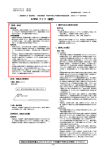
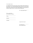
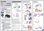
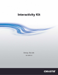
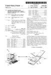
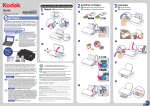
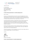
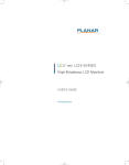
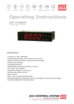
ID Walker p6-10 121332
9/20/12
8:27 AM
Page 6
touch technology review
Display Week 2012 Review: Touch Technology
2012 was the year that in-cell capacitive touch became real. It didn’t happen with big
fanfare; in fact, you had to put together pieces from the Symposium, the Monday Technology
Seminars, the Thursday Market Focus touch conference, and the exhibits to get the full
picture. But it was there and it’s significant.
by Geoff Walker
I
F you missed Display Week 2012, you
missed the most important event of the year
in the touch industry anywhere on the planet.
The amount of concentrated information
about touch available at Display Week 2012
was and will be unsurpassed by any other
conference anywhere this year:
• A 4-hour Short Course on Sunday
• Two 90-minute Technology Seminars
on Monday
• Three presentations at Tuesday’s
Investors Conference
• Six presentations at the Exhibitors Forum
on Tuesday
• 12 papers in the Symposium, mostly on
Wednesday
• Seven posters in Thursday’s Poster
Session
• 19 presentations in Thursday’s Market
Focus Conference
• Almost half of the 195 companies
exhibiting on the show floor (including
suppliers of touch screens, controllers,
At the time he wrote this article, Geoff
Walker was the Owner & Principal Consultant at Walker Mobile, LLC, a technical-marketing consulting firm. He has also been
Information Display’s Guest Editor for Touch
since 2007. By the time this article will be
published, Geoff will be a Senior Touch
Technologist at Intel. He can be contacted
at [email protected], 408/765-0056
(office) or 408/506-7556 (mobile).
6
touch-related materials and equipment,
market research, and touch-related
services such as bonding, optical
enhancement, and integration)
As the likely result of projected-capacitive
(p-cap) and resistive touch technologies
accounting for more than 90% of the number
of touch screens shipped in 2011 (according
to DisplaySearch’s latest 2012 data1), the total
number of touch technologies exhibited at
Display Week 2012 decreased. While 12
technologies were shown in 2011, this year
there were only six [p-cap, single-touch and
multi-touch resistive, infrared, embedded
(in-cell/on-cell/hybrid), and optical]. If you
looked closely, you could find one company
that sells (but wasn’t exhibiting) surface
acoustic wave, another that sells (but wasn’t
exhibiting) surface capacitive, and a third that
sells (but wasn’t exhibiting) electromagnetic
digitizers. Bending wave (from Elo TouchSystems and 3M) and force-sensing (e.g.,
from F-Origin) were nowhere to be found.
Projected-Capacitive (P-Cap)
The key difference in the p-cap suppliers at
Display Week this year was the number of
touch-module suppliers focused specifically
on meeting the needs of commercial applications in the U.S. The 15 suppliers in this
group included 3M, AMT, Bergquist, Dawar,
EETI, Emerging Display Technologies,
Gunze USA, Mitsubishi Electric, NLT Technologies, Ocular, Panjit, RitFast, SMK, Touch
Information Display 9/12
0362-0972/09/2012-006$1.00 + .00 © SID 2012
International, UICO, and Zytronic (there may
be others that the author missed). Prior to
Display Week, it was not unusual to hear a
p-cap touch-screen prospect say, “Well, who
else IS there besides Ocular and Touch International?” Several of 15 are first-time exhibitors at Display Week; others have changed
their product focus from resistive to p-cap.
There’s beginning to be a significant
amount of product differentiation between
these suppliers. Some of their differentiation
points include quick-turn prototypes, large
screens (e.g., 17 and 22 in.), a wide range of
screen sizes, cover-glass decoration (printing,
shaping, drilling, light pipes, etc.), lamination,
extended operating temperatures, working
with wet hands or gloves, stylus support, a
large number of simultaneous touch points,
operation in rain or saltwater spray, and
embedded GUI solutions.
In-Cell Touch: The Real Surprise at
Display Week 2012
Prior to Display Week 2012, it seemed as
though in-cell touch wasn’t making any significant progress. The number of shipping
products with in-cell touch could be counted
on just a few fingers:
(1) The line of Samsung digital cameras
that use pressed capacitive2 – with a user
experience significantly inferior to that of the
typical smartphone.3
(2) The 21.5-in. monitors from Integrated
Digital Technologies (IDTI) that use in-cell
optical.4,5
ID Walker p6-10 121332
9/20/12
8:27 AM
(3) The Microsoft Surface 2.0 that uses
Samsung’s SUR40 LCD with in-cell optical –
but requires severely limiting ambient light
(e.g., 50-lux maximum of incandescent light)
due to the touch system’s very high sensitivity
to ambient IR.6 While these products are all
shipping, they cannot be seen as successful
mainstream applications of in-cell touch.
What changed – and was reported in bits
and pieces at Display Week 2012 – was that
Synaptics made a breakthrough. Working
with multiple LCD manufacturers (with the
lead most likely being Sony) for the last year,
Synaptics determined that the only way to
create a smartphone-like touch experience
with in-cell touch is to use the same mutualcapacitive sensor architecture that has become
so successful in external touch screens, but move
at least one set of electrodes into the LCD cell
and find a way to significantly increase the
touch system’s signal-to-noise ratio (SNR).
Most of the papers published – mostly by
the display industry – on all forms of in-cell
touch (optical, voltage sensing, pressed capacitive, and self-capacitive) have reported SNRs
in the range of 10:1 (3 dB) or 20:1 (10 dB).
For example, there is a touch paper from this
year’s Symposium that claims an SNR of 10:1
is enough to meet the needs of a smartphone.
That may be acceptable in the lab, but it’s
certainly not acceptable in the real world.
Connecting a noisy AC adapter to a smartphone can raise the system noise floor by a
factor of 10, causing that touch screen to
become completely inoperative. The use of
a fine-tipped passive stylus – which will
become much more important with the launch
of Windows 8 – requires a much higher SNR.
Based on Synaptics’ work, a realistic minimum
SNR target for an excellent user-experience in
the real world is 50 dB (a little over 300:1).
Even higher is better for a passive stylus.
In order to accomplish a 50-dB SNR,
Synaptics concluded that (a) the basic touch
architecture must be “true” mutual capacitive
rather than any of the existing in-cell capacitive variations, (b) the touch controller and the
LCD driver must communicate with each
other, and (c) the LCD driver timing must be
modified to support both a display mode and a
touch mode. The Distinguished Paper entitled
“An In-Cell Capable Capacitive Touchscreen
Controller with High SNR and Integrated
Display Driver IC for WVGA LTPS Displays”
by Synaptics is the key document that describes
this technique.7 Among other details, the
Page 7
paper describes segmenting the VCOM plane
in an LCD to allow dual-purpose operation as
drive electrodes for “true” mutual-capacitive
touch sensing while still functioning as a proper
VCOM plane for display operation. Repurposing the VCOM plane as touch-screen
drive electrodes also produces a highly desirable
advantage: it moves the (typical) ±10 V VCOM
signal from the denominator of the SNR into
the numerator; i.e., instead of being considered
noise that detracts from the operation of the
touch screen, the VCOM signal becomes part
of the touch-screen operation. Even better,
higher VCOM voltages result in a higher SNR!
The sense electrodes are deposited in a
single layer of ITO on top of the color-filter
(CF) glass. This touch-sensor architecture is
shown in Fig. 1, taken from the aforementioned Synaptics Distinguished Paper.
Note that technically this architecture is a
hybrid of in-cell and on-cell, since one set of
electrodes is inside the cell (the segmented
VCOM plane) and one set of electrodes is
outside the cell (deposited on top of the CF
glass). However, the LCD industry is rapidly
moving towards calling all forms of embedded touch “in-cell,” on the grounds that it’s all
inside the LCD module. For example, Chimei
Innolux announced at Display Week 2012 that
it is going to brand all of its embedded touch
products from now on as “Touch On Display”
(TOD), intentionally obscuring the specific
touch-sensor architecture that’s used in a
given product. After all, why should anyone
care what touch-sensor architecture is used –
other than the manufacturer, of course!
960 × 540 (QHD, 275 ppi) LTPS LCD.
However, the LCDs are not actually identical;
visual inspection of the phones reveals that
the Sony Xperia P LCD uses RGBW pixels,
while the HTC EVO Design 4G LCD uses
RGB pixels.
These two shipping products use separate
(but linked) touch controller and LCD driver
ICs. Synaptics has announced that it has
started manufacturing a single IC that includes
both functions for 864 × 480 (WVGA) LCDs;
it has named this new product TDDI (Touch
and Display Driver IC). This integration
reduces component cost, of course, but it also
creates an IC that is unique for a particular
LCD. If another LCD manufacturer wants the
same functionality but is using an LCD with a
slightly different resolution (there are no standards for LCD resolution in the smartphone
market like there are in the PC market), then it
requires a new custom IC. This problem was
pointed out in a presentation entitled “Challenges and Opportunities in Touch Controller
Semiconductors” made by Randy Lawson, a
Senior Principal Analyst at IHS, during
Thursday’s Market Focus touch conference.10
In-Cell Touch in IPS-LCDs
In an IPS-LCD, the VCOM plane is located in
the TFT array, and it’s already segmented by
design. Without changing the various metal
New Shipping In-Cell Products:
The Next Piece of the Puzzle
On Monday of Display Week 2012, Bob
Mackey, Synaptics’s Principal Scientist,
presented a Technical Seminar entitled “Innovations in Touch Sensing.” 8 This presentation described with excellent clarity all the
possible touch-sensor architectures that could
be used in a smartphone (see pages 20–37 of
“Innovations in Touch Sensing). In this
presentation, Bob also stated that the Sony
Xperia P smartphone (shown in Fig. 2) uses
in-cell-touch electrodes configured as
described on page 11 of the Distinguished
Paper mentioned above (An In-Cell Capable
Capacitive Touchscreen Controller…). In a
Synaptics blog, it is stated that the HTC EVO
Design 4G also uses the same in-cell configuration.9 Both of these smartphones use a 4-in.
Fig. 1: Synaptics’s “true” mutual-capacitive
LCD in-cell touch-sensor architecture incorporates a VCOM plane that is segmented to
allow dual-purpose operation as drive electrodes for touch sensing while still functioning
as a proper VCOM plane for display operation. Sense electrodes are deposited on top
of the color-filter glass. Source: Synaptics.
Information Display 9/12
7
ID Walker p6-10 121332
9/20/12
8:27 AM
Page 8
touch technology review
Fig. 2: The Sony Xperia P smartphone uses
Synaptics’s “true” mutual-capacitive in-cell
touch-sensor architecture as described in the
company’s Distinguished Paper. Like most
current mobile devices, this smartphone uses
an IPS-LCD; the touch sensor is therefore
configured as shown in Fig. 3. Image source:
Sony.
agrees with this viewpoint, since it is likely
that we are actually talking about creating a
new display with embedded touch, which represents a new development cost that must be
amortized. The reason it’s a new display is
that the existing non-touch display is unlikely
to be made obsolete since the LCD maker
probably has OEM customers buying it that
use discrete or one-glass solution (OGS)
touch-screen construction. In-cell touch in
general is likely to add new products to an LCD
maker’s product line rather than replacing existing products. The management of this expanded
product line adds yet another implicit cost.
The new development costs to be amortized
include not only a new set of masks for the
TFT array, but also the customization of the
combined touch-controller and LCD driver
(TTDI) IC and firmware to match the particular display resolution being used. Non-recurring engineering (NRE) costs such as the
latter can be justified by the reduction in component cost achieved by the TTDI IC, but the
primary factor that justifies the development
of a new display with embedded touch is very
high sales volume. In the author’s opinion, it
therefore seems unlikely that in-cell touch is
going to spread into every LCD in an LCD
maker’s product line; it’s more likely that it
will be used only in the highest-volume
models – at least in the next several years.
Over the long term, as the overall penetration
of touch increases, it is possible that the
majority of mobile LCDs could include in-cell
touch. Usable in-cell capacitive touch in
larger-than-mobile LCDs is still under development; ITO-replacement materials such as
micro-scale metal mesh or silver nanowires
are probably the most significant enabler.
In-Cell Touch in VA-LCDs
The differences in touch-sensing architecture
between an IPS-LCD and a VA-LCD are
minor. The main difference is the location of
the VCOM electrode. In a VA-LCD, the
VCOM signal is applied to the ITO on the
inner surface of the CF glass. Again, the ITO
mask used to create the VCOM plane is
changed so that the VCOM segments can be
grouped differently to form drive electrodes.
Since the inner surface of the CF glass and the
top surface of the TFT array are only a few
microns apart, there is little functional difference between the VA and IPS configurations.
VA-LCDs do not use a shield layer on top
of the CF glass, so one additional ITO mask
is required in order to deposit a layer of segmented ITO to form sense electrodes on top of
the CF glass. The position of the drive electrodes in a VA-LCD is fixed by the VCOM
mask, while the position of the drive electrodes in an IPS-LCD is determined by the
LCD drive electronics. The touch-sensor
architecture of a VA-LCD is illustrated in
Fig. 4.
Chimei Innolux’s In-Cell Prototype:
The Final Piece of the Puzzle
The final piece of the puzzle came from the
author talking with several company represen-
IPS LCD
and ITO masks used to create the VCOM
plane, the VCOM segments can be grouped
differently to form touch-sensing drive electrodes. In most IPS-LCDs there is also a
grounded layer of ITO on top of the CF glass
that functions as a shield and anti-static
device; this layer can be segmented into sense
electrodes. Since all sense electrodes except
the one being sensed at any given moment are
grounded, the ITO layer still performs its
original function even though it’s been segmented. The touch-sensor architecture of an
IPS-LCD is illustrated in Fig. 3.
Adding in-cell touch to an IPS-LCD as
described in the previous paragraph is sometimes referred to as “no cost” because it may
require no mask changes. The author dis8
Information Display 9/12
1
2
Cover Glass (“Lens”)
Decoration
3
4
5
6
7
8
9
Top Polarizer
Shield/Sense (Y) Electrodes
Color Filter Glass
Color Filter
Liquid Crystal
TFTs & VCOM/Drive (X) Electrodes
TFT Array Glass
Fig. 3: Synaptics’s touch-sensor architecture for IPS-LCDs uses an ITO shield layer on top of
the CF glass (row 4 in the graphic). The shield layer is segmented to form sense electrodes
while still retaining its function as a shield. Similarly, the segments of the VCOM plane in the
TFT array (row 8 in the graphic) are grouped differently to form drive electrodes when the
display is operating in touch-sensing mode. Source: Geoff Walker.
ID Walker p6-10 121332
9/20/12
8:27 AM
tatives in Chimei Innolux’s booth on the show
floor. The Chimei representatives said that
they have recently prototyped in-cell touch in
one of their IPS-LCDs using Synaptics’s
touch-sensor architecture and an early sample
of Synaptics’s integrated touch controller and
LCD driver (TDDI) IC. The Chimei representatives said that their drive electrodes (VCOM
segments) use existing traces on the TFT array;
this is possible because the Synaptics TDDI
IC allows each row and column of the LCD to
be addressed individually. They also said that
they had not yet measured the SNR of their
prototype, but that they expected the value to
be similar to that reported by Synaptics.
Other Chimei Innolux Embedded
Touch Architectures
Chimei had the most extensive display of
embedded touch products on the show floor.
In addition to the IPS in-cell touch mentioned
in the previous paragraph, the company was
also showing or talking about the following:
• A self-capacitive set of electrodes on top
of the CF glass, in a diamond pattern
with true multi-touch (and as many as
300 pads!). A VP at Chimei told the
author that they had started this project a
long time ago when Chimei had a
restricted manufacturing capacity. They
did not want to add more machines to do
multiple layers, so they challenged their
engineering team to add touch using
the existing equipment. From such
challenges innovation is born.
• Standard on-cell mutual capacitive, which
Chimei calls OTS (on-cell touch screen).
This is a single layer of ITO with bridges,
using the standard Synaptics controller.
This configuration is not in volume production yet at Chimei because the yield
is only 60–70% due to the “double-sided
problem”; i.e., whatever you do to one
side of the CF glass is likely to damage
or affect the other side. For example, if
you do the CF side first, it can use
organic material; when you anneal the
ITO on the touch side, the high temperature damages the organic CF material.
• One-glass solution (OGS), which Chimei
calls “window integrated sensor.” (By
the way, the term “OGS” seems to be
slowly taking hold in the touch industry;
more than a few booths on the show floor
were using it.) Chimei’s yield with
Page 9
VA LCD
1
2
Cover Glass (“Lens”)
Decoration
3
4
5
6
Top Polarizer
On-Cell Sense (Y) Electrodes
Color Filter Glass
Color Filter
VCOM/Drive (X) Electrodes
Liquid Crystal
TFTs
TFT Array Glass
7
8
9
10
Fig. 4: Synaptics’s touch-sensor architecture for VA-LCDs incorporates an additional layer of
segmented ITO (row 4 in the graphic) that is deposited to form sense electrodes on top of the
CF glass. The segments of the VCOM plane underneath the CF glass (row 7 in the graphic) are
grouped differently to form drive electrodes when the display is operating in touch-sensing
mode. Source: Geoff Walker.
OGS is also in the 60–70% range
because it’s a difficult process that the
company hasn’t done before. (Other
vendors with more experience doing
OGS have reported higher yields.) The
touch sensor is a single layer of ITO with
bridges (Chimei claims that this is lower
cost than two layers with an insulator).
One of the difficulties is the temperature
limit of the black-mask (decoration)
material; if the ITO needs to be annealed,
the current black-mask material cannot
handle the high temperature.
Some Other Interesting Exhibits
100-µm cover glass. (Nippon Electric
Glass)
• A new method of making ITO invisible
by depositing the ITO on top of a 3-D
“moth-eye” nanostructure. The nanostructure makes the difference between
the ITO-coated and uncoated surfaces’
reflectivity (and also transmittance)
almost zero. (Sony Chemical)
• A 3H hardcoat film with more abrasion
resistance than an 8H hardcoat film.
(Oike)
• P-cap touch screens that work well with
water on the surface (several suppliers).
The Display Week exhibition is so chock-full
of interesting things to see that it’s almost
impossible to see it all. Here is a sampling of
exhibit offerings that the author found particularly interesting:
• A very clever method of having touch
buttons on a display without actually using
a touch screen. This is accomplished by
positioning long-range proximity sensors
in the bezel below the display and controlling their sensing pattern. (Azoteq)
• A Specific Absorption Rate (SAR) proximity sensor with optimization for human
detection (vs. inanimate objects). This is
accomplished using two capacitive
proximity sensors and digital signal
processing. (Semtech)
• A curved touch screen (shown in Fig. 5)
built on a 50-µm glass substrate with a
Fig. 5: Nippon Electric Glass created this
10.8-in. curved p-cap touch-screen reference
design on a 50-µm glass substrate with electrodes deposited on both sides and a 100-µm
cover glass. The minimum radius of curvature is 65 mm. Nippon Electric Glass envisions applications (with a curved display) in
automotive-navigation systems, tablet PCs,
and smartphones. Source: Geoff Walker.
Information Display 9/12
9
ID Walker p6-10 121332
9/20/12
8:27 AM
Page 10
touch technology review
• Extensive parameter tunability on Baanto’s
latest optical touch screens. Some of the
parameters include touch-area detection,
minimum touch time before a new touch
is recognized, and shadow touch density.
• A new laser-cutting method for aluminosilicate (toughened) glass that loses only
10% of the glass’s strength. (Asahi Glass)
• A plug-in for Adobe Acrobat that allows
four users to simultaneously edit the
same drawing or document on a multiuser touch table. (Circle 12)
• Re-designed spacer dots in a four-wire
resistive touch screen that reduce the
touch-force required for activation to
only 2 or 3 grams – it feels the same as
p-cap! (Fujitsu Components)
• PQ Labs’s “high-finger-count” infrared
touch algorithms licensed to IRTouch
and used in a 10-touch 22-in. IR touch
screen. A representative in the IRTouch
booth said that there’s a lot of interest in
the product, but that it’s not concentrated
in any one market (i.e., there isn’t one
common application).
• Stantum’s latest digital-resistive touch
screen (made by Nissha Printing and
shown in Fig. 6) with Peratech’s “quantum tunneling” pressure-sensing material
in a layer only a few microns thick
between the film and the glass.
• A p-cap mutual-capacitive sensor (in
3.5-, 5-, and 7-in. sizes) that uses a single
layer of ITO without bridges or metal
routing traces. This is accomplished by
running drive electrodes vertically down
the sensor and forming individual sense
pads in a column beside each drive electrode. This layout also allows the sensor
to be borderless on three sides. The sensor is built on a substrate of Corning’s
0.1-mm “Willow” glass and laminated to
a 0.5-mm cover glass with 0.1 mm of
OCA for a total stack-up of 0.7 mm.
This is about the same thickness as an
OGS configuration, but without the associated yield problems. (TouchTurns)
• An ordinary 7-in. p-cap touch screen
(shown in Fig. 7) that works very well
with a passive 2-mm-tip stylus. (Emerging Display Technologies)
Touch at Display Week is Evolving
In the beginning of this article there was a
mention of the increased number of p-cap
10 Information Display 9/12
Fig. 6: Stantum’s latest digital-resistive
(iVSM) touch screen uses Peratech’s “quantum tunneling” pressure-sensing material in
a layer only a few microns thick between the
film and the glass. Note the Nissha branding;
Stantum and Nissha Printing have partnered
to produce a line of “Fine Touch Z” touch
screens in sizes 5–12 in. Source: Geoff Walker.
module suppliers at Display Week this year
that are focused specifically on meeting the
needs of commercial applications in the U.S.
It seems clear that the exhibition/conference
portion of Display Week has become the
number one place for U.S.-based commercial
touch prospects to look for suppliers and new
Fig. 7: A 7-in. p-cap touch screen from
Emerging Display Technologies supports a
passive stylus with a 2-mm tip. The author
wrote his name on the screen with palm contact; there were no spurious points recorded
and the ink was noise-free with normal stairstepping that software could easily smooth.
Source: Geoff Walker.
technology. The majority of the 31 presentations on touch in the bulleted list at the beginning of this article (presentations made in the
Market Focus Conference, Investors Conference,
Exhibitors Forum, Technology Seminars, and
Short Course) were made by American companies.
In contrast, the touch portion of the Symposium is dominated by the Asia-centric display
industry. Of the 19 papers and posters on
touch presented in the Symposium, 10 were
written from a display-industry perspective,
reflecting the very strong interest of the display industry in embedded touch; five were
written from a touch-screen-industry perspective; and four were written from an “other”
perspective (glass-2, bonding, and proximity
sensing). While this difference between the
exhibition/conference and the Symposium
parts of Display Week is not necessarily a
problem, the author would definitely like to
encourage the touch-screen industry to write
more, higher-quality papers or posters for the
Symposium. In that way, the touch portion of
Display Week will become all it can be.
References
1
DisplaySearch, “Touch Panel Market Analysis
2012 Annual Report” (July 2012).
2
J. Lee et al., “Hybrid Touch Screen Panel Integrated in TFT-LCD,” SID Symposium Digest,
paper 24.3.(2007).
3
Samsung Electronics America, Inc., “User Manual
- ST700,” version 1.3, pp. 21-22 (March 2011).
4
http://www.idti.com.tw/solution.php, retrieved
7/13/12.
5
http://ntuzhchen.blogspot.com/2011/03/idti-incell-touch-panel.html, retrieved 7/13/12.
6
Samsung Electronics Co., Ltd., “Samsung
SUR40 for Microsoft Surface Venue Readiness
Guide,” pp. 7-13 (December 2011).
7
M. Ozbas et al., “An In-Cell Capable Capacitive Touchscreen Controller with High SNR and
Integrated Display Driver IC for WVGA LTPS
Displays” (ISSN 0097-966X/12/4301-0485)
(paper 37.1), SID Symposium Digest 49, 485-488
(2012).
8
B. Mackey, “Innovations in Touch-Sensing,”
presented as Seminar M-3 at SID Display Week
Conference, Boston, MA, June 2012 (downloadable from http://blog.synaptics. com/wpcontent/uploads/2012/06/SID_2012_Seminar
M-3_CapacitiveTouch_Mackey_Present.pdf).
9
http://blog.synaptics.com/?p=104, retrieved
6/20/12.
10
R. Lawson, “Challenges and Opportunities in
Touch-Controller Semiconductors”, presented at
SID-IMS “Future of Touch and Interactivity”
2012 Conference, Boston, MA (June 2012). ■