1
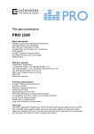
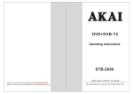
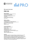
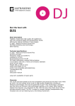
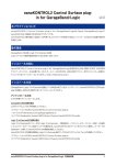
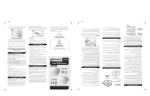
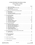
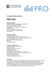
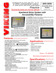
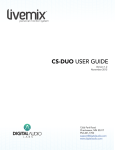
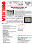
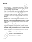
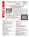
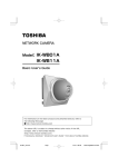
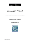
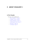
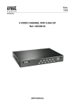
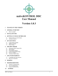
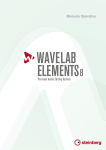
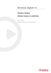
T H E A L T O G E T H E R User’s Manual Version Beta 1.22 Page | 2 0_Introduction The Altogether (© 2015 Hugh Lobel), is a holistic electronic music production and performance system for improvisation, performance, and composition. The Altogether is a DAPE, or Digital Audio Performance Environment, functioning similarly to a DAW (Digital Audio Workstation), but designed with a special modular structure built for exploration and performance. The name is inspired by the 90’s and 2000’s EDM band Orbital, who’s sixth album was titled The Altogether. The Altogether was built in the programming language Max/MSP (now just called Max), and many of the processes in the program are directly accessing the built in library of effects. Other tools are processes built from the ground up in the language, and provide completely unique sounds and functions. The Altogether does not use any third-‐party externals, and all effects are either built by the creator, or are modified from the Max Examples library. Because of the close relationship between Cycling 74 (the developers of Max), and Ableton, many of the interactive buttons and bits used in this code resemble the sliders and dials found in Ableton Live. This should make it easier for Ableton users to feel at home in The Altogether, but this does not mean that it can be used directly in Ableton. A Max for Live version may be released in the future, but there is no current timeline for development. The Altogether is currently in beta form, but that does not mean that it is incomplete. New features will be added to the program in the future, but it is highly functional in its current state. The program has already been used to create and perform complete works, and performances using the Altogether have occurred across the United States and in parts of Europe and Central America. The program may be used to create, perform, and distribute your own music, and no type of recognition is required. However, I would love to hear about your use of the program and I’d love to hear the music that you create with my toolbox! Please feel free to e-‐mail me to tell me about your creations and to share your music with me. I can be contacted at [email protected]. P.S. This User’s Manual is a work in progress. I will be releasing this as I complete it, so that users may use what I’ve finished so far to help them get started. P.P.S. Keep your eyes open for special sections with the Important header. These paragraphs have information that shouldn’t be missed and will go a long way in helping you get the most of out the program. Page | 3 Table of Contents 0. Introduction 1. Installation Guide a. Issues with Installing The Altogether on OSX b. Notes about running The Altogether on PC 2. Getting Started a. The File Structure, and Opening The Altogether b. Creating a New Project c. The System Board 3. Audio Status Window 4. The Pedal Board a. Saving/Loading Pedal Boards 5. Using Effects a. Controlling Effects b. Time c. Common Parameters d. Other Important Parameters 6. Connecting Effects 7. Effect List (with brief descriptions) a. Using Audio Files in Saved Boards 8. Recording Tools 9. The Performer View 10. Automating Parameters a. Using Automator Boards i. The Automation Message ii. Automation Groups iii. Example Automation Messages b. Using Controllers Page | 4 11. Advanced Automation 1: The System Score a. How Does the System Score Function? b. The System Score Automation Message c. Messages with Multiple Parameter Controls d. Events e. Controlling the System Score 12. Advanced Automation 2: The Secondary Scores 13. Projects a. Designing Projects b. Saving Projects c. Loading Projects 14. The Metronome 15. The Mixer 16. Known Bugs 17. FAQ 18. Contact Information Page | 5 1_Installation Guide OSX Installation: 1. First download the compressed folder from the website www.hughlobel.com/software.html. Make sure to download the file labelled “The_Altogether_MAC.zip.” 2. Once the file is downloaded, double click the zipped file to decompress it. If you downloaded the file with Safari, it may be automatically unzipped. After the decompression process, you should see a folder titled “The Altogether Beta” with a number for the current build. 3. Important: You may move this folder to any location on your computer, including your applications folder, but DO NOT remove any of the initial files from this folder. Moving files may cause the program to stop working. 4. Optional: You may create an alias for your desktop if you want quicker access to the program. In order to make an alias, right click on The Altogether application, and select “make alias.” This will add a new icon in the folder called The Altogether Alias. This icon may be moved to any location on your computer, but the original application needs to stay in the folder. 5. Once you’ve positioned your folder to the location that you want, the program can be opened by double clicking on “The Altogether” icon. It looks like a circle with the letter 7 in it (this is the Max 7 default icon. This will change in a future release.) Double-‐clicking the icon should open the program. Be patient, it may take a minute to launch. Windows Installation: 1. First download the compressed folder from the website www.hughlobel.com/software.html. Make sure to download the file labelled “The_Altogether_PC.zip.” 2. Once the file is downloaded, you must decompress it. Do this by right clicking on the zipped file and select Extract All… from the drop-‐down menu. Choose the location and the folder name (if you’re uncertain, leave the defaults as they are), and press Extract. After the decompression process, you should see a folder titled “The Altogether PC”. Inside this folder is another folder titled “The Altogether Beta” with a number for the current build. This is the folder containing the application. 3. Important: You may move this folder to any location on your computer, including your applications folder, but DO NOT remove any of the initial files from this folder. Moving files may cause the program to stop working. 4. Optional: You may create a shortcut for your desktop if you want quicker access to the program. In order to make a shortcut, right click on The Altogether application, Page | 6 and select “send to...”, then “Desktop (create shortcut.) This will add a new shortcut on your desktop called “The Altogether Beta 1.x Shortcut”. 5. Once you’ve positioned your folder to the location that you want, double clicking on “The Altogether” icon or your optional shortcut will open the program. It looks like a circle with the letter 7 in it (this is the Max 7 default icon. This will change in a future release.) Double-‐clicking the icon should open the program. Be patient, it may take a minute to launch. 1a_Issues with Installing The Altogether On MAC (or how to fix the “downloaded app is damaged” problem.) Some people have difficulty running The Altogether after downloading and uncompressing the program. If you’re getting a message saying “downloaded app is damaged and can’t be opened”, this is actually the operating system keeping you from using applications that aren’t from Apple identified developers. To fix this, you must change your settings to allow the computer to run applications from anywhere. Easy and clear directions on how to fix this issue can be found here: http://www.tech-‐recipes.com/rx/45404/mac-‐downloaded-‐ app-‐is-‐damaged-‐and-‐cant-‐be-‐opened-‐error-‐solved/ 1b_Note about Running The Altogether On PC The Altogether takes time to load on both OSX and Windows, but it seems to take longer to open properly on some PCs. Please be patient while the program initializes. Also, be aware that after the program opens, it may not work properly for the first minute or so. Keep an eye on the CPU meter. If the number is 0 and/or is not fluctuating, it’s likely that the program is still loading some of its features. Creating or opening Pedal Boards while the system is loading will result in non-‐functioning boards. Do Not Worry about this! Simply wait until you start to see those CPU numbers wiggling around and try again. Once the system is fully up and running, boards should work exactly as they are supposed to. Page | 7 2_Getting Started Working in The Altogether can be overwhelming at first. I’ve gone to great lengths to make the program as intuitive as possible (and I’m continually working to improve the user experience,) but the program is very complex. Chapter 1 will walk you through the download and installation process for The Altogether on both Mac and PC. Chapters 2-‐9 will walk you through the beginning process of starting your first project and working with the different boards. Chapters 10-‐12 will guide you through the use of automation, which will help you bring your projects to life. Automation provides a variety of methods to control change in your projects over time. Chapter 13 will guide you through the process of building, loading, and saving projects. Chapters 14-‐15 cover the Metronome and the Master Mixer, giving you a look at the final tools available. Chapters 16-‐18 wrap up the manual with a list of known bugs, an FAQ, and the creator’s contact information. 2a_The File Structure and Opening The Altogether Let’s begin by examining The Altogether’s file structure. Once the zipped file has been uncompressed, a folder will appear in your chosen location on your hard drive. It’s important that the files in the folder stay in this folder and not be moved elsewhere. Moving any of these files can break the program. If you’re on an Apple computer running OSX, and you downloaded the correct file, your folder should contain the following items (not necessarily in this order): 1. The User Manual 2. A .pdf explaining how to fix the “application is damaged” issue 3. A folder called Project Files. This folder includes the following subfolders: a. Audio Files b. Saved Automators c. Saved Boards d. Saved Scores e. Saved Projects Page | 8 4. The Altogether application (.app) file The Altogether is opened in OSX by double clicking on The Altogether application file. If you are on a PC running Windows, and you download the correct file, your folder should contain the following items (not necessarily in this order): 1. The User Manual 2. A pdf discussing the loading issue. 3. A folder called Project Files. This folder includes the following subfolders: a. Audio Files b. Saved Automators c. Saved Boards d. Saved Scores e. Saved Projects 4. A folder called “resources” 5. The Altogether .mxf file 6. The Altogether executable (.exe) file. The Altogether is opened in Windows by double clicking on The Altogether executable file. 2b_The Project Load Screen Upon opening The Altogether, you will be greeted with the Project Load Screen. This screen allows you to start a new project or open a saved project. Fig. 1: The Project Load Screen Let’s look at the options that we have available, and how to use them. Page | 9 1. Open New Project: In order to start a new project, click the large button below the text. 2. Open Saved Project: Here the user is provided with two methods of opening a saved project: a. Open Project File…: If your project file has been saved in a location other than the Saved Projects folder, you’ll have to search out and select the project using the open dialogue window. b. Select Project File…: This menu will be populated by any files that are currently saved in the Saved Projects folder. Keeping your project files in this folder will make it easier to quickly pick your work back up where you left off. Building, Saving, and Loading Projects will be discussed in detail in Chapter 17. If this is your first time running The Altogether, your best bet is to start by opening a New Project. Click the large button beneath the text Open New Project, and let’s get started! 2c_The System Board After you select New Project, you will be brought to the System Board. This is the part of the program that sends sounds out to your speakers and gives you access to all of the various tools available in the program. The System Board MUST REMAIN OPEN while you run the program; closing the System Board window will stop everything immediately and will shut the program down. The System Board may not look like much, but it’s loaded with information and features. We’re not going to be making music from this window (we’ll be doing that on our Pedal Boards), but this screen will be invaluable to us as we build and navigate our projects. Let’s take a look at the System Board and examine all of its features: Page | 10 Fig. 2: The System Board 1. DAC toggle: This speaker-‐shaped toggle is the Digital-‐to-‐Audio converter. When this toggle is turned on (highlighted, as seen in this image), the program’s audio engine is running. Toggling this off (the speaker image will turn dark gray) will stop all audio processing and cut out any sounds currently being sent out to your speakers or headphones. 2. Add New Board: Clicking Add New Board will generate a new Pedal Board. Pedal Boards are where all sounds in the program are generated and manipulated. This button can be clicked multiple times to generate as many boards as needed. Pedal Boards are described in detail in the following section. 3. Load Board File: Pressing this button allows the user to re-‐load any previously saved Pedal Board. More information can be found in the “Saving/Loading Pedal Boards” section. Page | 11 4. Master Gain Sliders and Meters: The output signal volume is displayed in the black bars, while the two striped sliders allow the user to adjust the final volume. Moving the left channel slider automatically moves the right channel slider. 5. CPU Monitor: This number shows what percent of your computer’s CPU is currently being used by The Altogether. If this number gets too close to 100%, slowdown may occur and the audio may begin to cut in and out. Overloading the CPU can cause the program to crash. 6. Performer View Toggle: Toggling this on expands the System Board window to reveal the performer view. Toggling this off contracts the window again, hiding the performer view from the screen. More information can be found in the “Performer View” section. 7. Recording Tools: This set of tools allows the user to record any signal going out to the speakers. Performances and explorations can be recorded for posterity or future manipulation. More information can be found in the “Recording Tools” section. Page | 12 3_System Setup in the Audio Status Window Setting up your computer’s audio system to work with The Altogether is easy, and for the most part automatic. If your computer uses a single sound card then everything should be setup automatically. Plugging in an audio interface before starting The Altogether will allow the program to recognize it automatically. However, if your setup uses multiple sound cards or interfaces, it may be necessary to set up your audio manually. To do this, navigate to the Audio Status Window by “View Audio Options” in Altogether Windows on the program’s menu bar. Fig. 3: Selecting “View Audio Options” from the menu bar Fig. 4: The Audio Status Window Setting up your computer to work with The Altogether is as easy as selecting the appropriate driver from the Driver menu. For Macintosh computers, you’ll want to select “Core Audio”. For PCs, you’ll want to select the driver for your sound card. Input Device selects the microphone or interface that will send a signal into the system for manipulating live performances. Output Device should be set to the speakers or interface that your project’s sound will be sent out to. The Audio Status Window was developed by Cycling 74, and more detailed information can be found in the online documentation for Max 7: https://docs.cycling74.com/max7/tutorials/04_mspaudioio Page | 13 4_The Pedal Board New Pedal Boards can be added to your project by clicking “Add New Board” in the System Board window, or by selecting “Add New Board” from Boards on the program’s menu bar. Fig. 5: Selecting “Add New Board” from the menu bar. Fig. 6: A Pedal Board in its Default State A newly loaded pedal board contains only a few items: • The outline of a rectangle in which the first process may be loaded • A drop-‐down menu with the names of each available effect to choose from • A tool to provide the current module with a unique automation identification name • The option to add a new module to the right or below the default module, and the option to save the board. The default board may not seem like much, but as soon as a process is selected from the drop-‐down menu, the program really starts to come to life! The available processes fall into four categories: 1. File Players: These modules allow the user to load up and play back audio files. 2. Synthesizers: These modules allow the user to synthesize and create new sounds. Synthesizers can be controlled by any USB keyboard 3. Filters: Take in audio from a file player, synthesizer, or live input and changes the sound on a variety of ways. Page | 14 4. Buffer Effects: Like filters, buffer effects process sound from a file player, synthesizer, or live input, but do so through a process called buffer manipulation. These effects are varied and exciting. 5. Mastering: These are filters and tools that are used to provide clarity or balance to the mix. 6. Control: This currently contains a single effect, the Message Board, which provides an alternate space for building, saving, and reading system scores. Selecting any process from the menu immediately loads it into the previously blank module space, complete with a unique interface that provide tools to control the parameters of the effect. A pedal board with only one module is useful, but a pedal board with a variety of modules has a variety of uses! To add more modules to a board, simply click on of the add buttons on the right of the module or below the module. These buttons are the small squares with circles inside of them… ß this button will add a new module to the right of the current one. Fig. 7: A Pedal Board with the EZ_FilePlay module loaded. ^-‐-‐-‐-‐-‐ Clicking this button will add a new module below the current one. As many new modules as you want can be added to your pedal board, up to a grid of 64x64 modules. New pedal boards can be made at any time, and any number of the individual effects can be loaded onto one or more boards! Page | 15 Fig. 8: A pedal board with six modules loaded, including a file player, a buffer board, a pitch shifter, a retuner, a granular machine, and a signal hub. 4a_Saving/Loading Pedal Boards Entire compositions can be designed and planned on these pedal boards, and it’d be a shame not to be able to save your work. Fortunately, The Altogether allows the user to save and reload any number of pedal boards. When you’ve finished building your pedal board, clicking the “save patch” button will open a save dialogue box where you can name your board and choose the save location for your file. When the save dialogue opens, another dialogue window will open asking you to name your board. Naming your boards should help you keep track of them as your project grows. Once a board has been saved, the buttons to add modules will be removed from the board. Effects may still be swapped out, parameters may be changed, and the board may be re-‐ saved, but no new modules can be added. Important: Although it’s not required, it is strongly recommended that pedal boards be saved in the “Saved Boards” subfolder of “Project Files” in the Altogether folder on your computer. Loading a saved board is as simple as clicking the “Load Board File” from the System Board or from the menu bar. Page | 16 Important: There’s currently a big bug in the save/load structure, but it’s easy to avoid! Every module MUST have something loaded into it in order for a file to save successfully. If you find that a saved board won’t load, it may be because you saved it with blank modules in them! This problem will be resolved in a future update. Page | 17 5_Using Effects Each module effect has a unique function, and a unique design to go with it. Although it may look overwhelming at first, there is a general workflow that each effect has in common. Let’s look at this workflow now, to help you get started on creating your first project. Fig. 9: The Resonant Filter Module We’ll take the Resonant Filter as our example module. It’s not the simplest, but it’s not the most complex effect either. The Resonant Filter takes in sound from a live instrument or from another part of the project, and filters out certain frequencies. The squiggles in the middle represent the shape of the signal after it goes through the filter. The Resonant Filter, like the majority of the tools, includes a series of menus and dials allowing the user to modify the filter’s function. Notice that a number accompanies each parameter. These numbers guide us through the best order of operation for setting up the module. By following the numbers and changing parameters one at a time, you’ll find the most effective way of moving through the initial setup for each process. Page | 18 5a_Controlling Effects Modules are controlled via a wide variety of objects that can be manipulated with the mouse and keyboard. Let’s quickly look at the different type of objects, and how they give us control over our loaded effects. Fig. 10: List of controllable objects found in The Altogether 1. Dials – These are knobs that can be turned up (clockwise) or down (counter-‐ clockwise) to change a parameter within a lower and upper range. 2. Toggles – These boxes allow us to turn Off and On various functions. When the X is highlighted in the box, the toggle is ON. When the X is dark, the toggle is off. 3. Number Boxes (Integer vs. Floating Point) – These allow us to control parameters by directly typing the value we want to set it to. These give us more precise control compared to dials. 4. Buttons – Certain processes require a simple click to activate. Usually buttons look like dark squares with circles in the middle, or simply circles without the square. When the boxes are clicked the circle quickly lights up, then turns dark again when we release the mouse button. 5. Message Buttons – These function like normal buttons, but include a message in them. They are rectangular, and are longer or shorter depending on the length of the message. 6. Sliders – Sliders are a good alternative to the dial, and function similarly. Sliders can set a single value or a low and high range for parameters. Page | 19 7. Menus – Allow us to select from a series of options. Perfect for creating our input and output IDs, and also good for choosing between algorithms or processes. 8. Keyboards – Some modules are playable, or are pitch-‐centric. In these cases a keyboard will appear in the module. These keyboards can be played by clicking on them, or, in the case of some synthesizers, can be controlled by plugging in a USB keyboard. 9. Multi-‐Sliders – These are like regular sliders but allow you to set multiple parameters. Perfect for creating ADSR envelopes. 10. Line Graphs – A few modules provide line graphs that can be changed and manipulated. Currently this is used in the Gater to draw the shape of the pulse. 11. The EQ Graph – Used in the StudioEQ, this detailed graph has five points that map to the five steps of the equalizer. Each point can be clicked-‐and-‐dragged around the graph to create the EQ shape. 5b_Time Many effects and controls in The Altogether are concerned with time, or how quickly or slowly various events play out. Time is critical in music, and when it comes to determining how events occur, precision is important in how we measure time. In order to give maximum precision to the user, time is measured in milliseconds. 1000 milliseconds = 1 second, so it’s common to see large numbers when looking at time, delay, and duration parameters. This is useful if we want to specify very small increments of time, such as 1/100th of a second. In this case, the value we would enter would be 10, for 10 milliseconds. On the other end, long durations require very large numbers. 1.5 minutes becomes 90,000 milliseconds. Make sure to always keep this in mind when setting time-‐based parameters! 5c_Common Parameters Almost every module have the same first three parameters, and these are crucial for setting up the process. All three parameters must be set in order for the module to properly work. Because of their importance, each of these parameters are explained in more detail below. 1. Choose Input: With the exception of the file players and synthesizers, every process begins by selecting the input. This is where we choose what sound to send into the process. This parameter is presented as a set of drop-‐down menus. Select both a letter and a number, which should match up with the output of the source process. Page | 20 Matching outputs and inputs are crucial to building a successful patch, and this process is described in more detail in Chapter 8. 2. Choose Outputs: Each effect provides routing to output the signal in two directions. The default output is set to Master Out, or the stereo signal that goes to your speakers. If you want to hear the output signal directly, make sure to set at least one output name to Master Out. Chaining effects together will be described in more detail in Chapter 8. 3. Volume (abbreviated as Vol) This is presented as a large dial (although sometimes a small dial is used to save on space) that can be turned to control the output volume of the module. At the far left position, no sound will come out. At the 12 noon position, the signal will be at full volume, and moving the dial to the far right boosts the signal to be twice as loud as the original signal. Look back to the previous page and try to find these three parameters. • • • Choose Input is at the top, and this will be the case in every module. In contrast, Choose Outputs is at the bottom. They may not always be in the center of the module, but the outputs will always be somewhere along the bottom. The Volume Dial changes position frequently, so make sure to take a moment to look for it when you load a new module. In this effect it’s near the top left, but in other modules it may be in the center, or close to the bottom right. 5d_Other Important Parameters Although the previously listed parameters are by far the most common, some other important common parameters can be reviewed as well. 1. Waveforms: In the SAH and Additive Synthesizers, sound generation starts by choosing the type of waveform to use. Each waveform has a unique quality, and mixing and matching unique sounds can make all the difference. 2. Open Audio File/Load: The EZFilePlay and FilePlayer loads and plays back audio files into buffers and players. Pressing the Open/Load button opens a dialogue window where you can navigate your system to find the audio file you want to add to the project. If you want the audio file to load automatically with a saved board, followed the instructions outlined in the chapter “Using Audio Files in Saved Boards.” 3. Buffer Size: Buffer effects work by loading “chunks” of live sound into a temporary storage space. This storage space is referred to as a buffer, and the buffer size is measured in milliseconds. Most buffers default to about 2000 milliseconds (or 2 seconds), but they can be shrunk or extended. If your sound is choppy and you want something a bit smoother, try extending the size of the buffer in your effect. There’s Page | 21 4. 5. 6. 7. 8. no limit to the size, so try something like 10,000 (10 seconds) out, or even something as large as 1,000,000 (1,000 seconds!) A lot of large buffers could eventually cause your RAM to fill up, but most computers have the ram to handle plenty of large buffers. Frequency (Freq.): Many filters work by processing a signal around a specific part of the frequency spectrum. The frequency spectrum typically extends from between 20hz to 2,000hz. Generally, focusing on a low frequency will result in a low-‐ sounding filtered sound, but sometimes the effect will be the opposite. If you see “Freq” as a dial on a filter, try playing with this dial can have a huge effect on the process. Q: A filter’s Q factor can be thought of as the “sharpness” of the effect. If you like the sound you’re creating, but you wish the effect was more pronounced, try turning the Q factor up. If you want the effect to be more subtle, try bringing the Q factor down. The Keyboard: If you see a piano keyboard in the module, this means that you’ve chosen either a module that can be played, or a module that filters or modifies a sound around specific pitches. Try playing the keyboard to generate sounds on the synthesizer or choose a pitch to filter the sound around. View Routing List: This button appears on a few of the more complicated modules, where there may not be enough room to place numbers on the parameters. Pressing this button opens a secondary window with a list of the parameters along with their assigned numbers, for reference. Flonum (or no name at all): Important! This is an error in the program that occasionally happens when you choose one module effect and then re-‐load a different effect into the same space. If you see a dial labelled “Flonum” or without a name at all, it means the system forgot what to call that particular dial. The dial will still serve its original function, and if you load the effect in a new module space or on a new board, the dial’s name ought to appear correctly. Page | 22 6_Connecting Effects Fig. 11: A Pedal Board with a SAH synthesizer, a degrader, a hub, and a reverb unit loaded and chained together. Spend a minute looking over the effects that have been loaded into this pedal board, as we’ll be using it as the primary example for our discussion on connecting effects. Important The Altogether was designed as an emulation of a guitar effect board. Imagine your favorite guitarist playing in your favorite band. That guitarist probably isn’t sending the sound of their instrument directly into their amplifier, right? Guitarists around the world use effects to Page | 23 process and shape their sound into something truly unique to their playing styles. Typically the guitars sound goes into a single effect pedal, but that pedal is likely then chained on to another pedal, and maybe many more before it reaches the amplifier. Think of your Altogether Pedal Board as a guitar pedal board, but one where you can load up synthesizers and audio files as well as live instruments, where there’s no limit to the number of effects you can load (save for the limit of what your CPU can handle) and where the signal chain can be routed in several directions at once! Maybe now you’re starting to get a good idea of this software’s full potential! Let’s look at how to do this. ~~~ As stated before, each module (besides the synthesizers and the file players) begins by choosing where to take a signal in from, and where to send the processed signal out. Look at the module on the top left. This is our SAH synthesizer. In place of choosing an input, the SAH begins by selecting a waveform, and playing the keyboard to generate sound. In the bottom left corner of the SAH, we see two outputs chosen, A1, and Z0. ~~~ The Input/Output List: Each input/output is created by the user by making a pair of selections from drop-‐down menus. The first menu is populated by Master (or Mic on inputs), and letters A-‐Z. The second menu is populated by Out, and the numbers 0-‐16. One selection must be made from each, so that the output or input is set to a letter and a number (like A1 or Z0.) If the sound source is going to be a microphone or input then “Mic 1” must be selected for the input (or 2-‐16 if you’re using multiple mics.) Also, in order for sound to go out from a module to your speakers, “Master Out” must be selected for the output. ~~~ Let’s look at the outputs we’ve selected for the SAH. Output 1 is set to “A 1”, while Output 2 is set to “Z 0”. Since neither output is set to Master Out, the sound will not go from this module to the speakers. Now let’s look at the degrader, the module in the top right corner. The degrader does require an input source, and “A 1” has been selected here. Notice that this is the same as the first output for the SAH. The outputs for the degrader are “B 1” and “Z 0”. Now let’s glance to the Hub module on the bottom left. This takes up to four inputs and mixes them down into a single stereo out. The Hub is taking “A 1” and “B 1”, and outputting to “C 1” and “Master Out.” Finally, the reverb in the bottom right is receiving “C 1” and outputting to “Master Out” and “Z 0”. Note that Z 0 never got received by any effect, so the signals going here will never be picked up by anything, or heard in our speakers. ~~~ Page | 24 Input/Output Pairing: The process of chaining modules together is as easy as setting the output of the first module to the same Letter-‐Number pairing as the input of the second module. If you want one module’s signal to go to multiple locations, set each destination module’s input to the same Letter-‐Number pairing as the signal source’s output. ~~~ Let’s follow the sequence of pairings in our demo pedal board. 1. The entire signal chain for this board originates from the SAH synthesizer. It is sending its signal to A 1. 2. Two boards are receiving A 1’s signal: The degrader and the hub. 3. The degrader is receiving the signal from the SAH, processing the sound, and sending the new signal out to B 1. 4. The Hub is receiving signals from both A 1 AND B 1. The hub is a mixing console. Note that I’ve set the volume for A 1 to be much louder than B 1 in my hub. This is so I can get the perfect mix between the two signals. The hub is outputting its mixed down version of both signals to two locations: “C 1” and “Master Out”. Selecting Master Out means that the mixed down signal from the hub will go to our speakers for us to hear. This is the first part of the signal chain that we’ll actually hear. 5. Finally the reverb unit is picking up the hub’s output from C 1. The reverb unit is processing the sound and turning it into a reverberated signal. The reverb sound is going out to “Master Out.” To review this process: We made a synthesizer, and decided to degrade its sound. Then we decided that we wanted to hear both the degraded sound and the original sound, but not equally, so we mixed them together in the hub. The mixed together sound is what we finally sent out to our speakers, but we also sent it to a reverb unit. The reverb unit also went out to our speakers. The resulting sound would be our SAH synthesizer, with a little bit of distortion, and some nice reverberation. Try recreating this board, then try making your own pedal boards with complex signal chains. This signal chain is actually pretty basic compared to some combinations! Important: Number-‐Letter pairings made on one board can be received on other boards. So if you like a sound you’re making in a full board and want to continue to change it, just make a new board and send the signal from board 1 to board 2. There aren’t any additional procedures to do this, just make sure to pair your inputs and outputs between your boards! Page | 25 7_Effect List (with brief descriptions) File Players File_Play: This full-‐featured file player includes the ability to load a file into a buffer, choose your playback range, and even choose the speed and pitch of playback (either connected, or separate functions.) Limited to loading one file at a time, but provides complex control. Allows fast file swap in conjunction with a BufferBoard. EZFilePlay: Stripped back controls with cleaner and quicker functionality. Can load up to four files into a single module, and can swap files out on the fly by switching to a buffer stored on a BufferBoard. Synthesizers SAH: Sample and Hold synthesizer, re-‐creates a method for quickly generating a variety of sounds that was used on old arcade and console sound cards. Good for re-‐creating your favorite Atari sounds, or making something really bizarre! Add1t1ve: A three-‐oscillator wavetable synthesizer with a good bank of waveforms, an amplitude envelope, and a sequencer. LFO features coming soon. Tambura: This synthesizer is a drone machine, devised as a bank of sine waves that re-‐ create the spectral color of the Indian Tambura. A very good plug and play drone tool that allows you to set the tuning and pitch center. Includes flange slider. Vocoder: Classic vocoder effect. Input signal can be filtered through up to eight different pitches, or a secondary signal can be chosen from another module like Add1t1ve or from a live source. Filters FilterShaper: A multi-‐purpose tool that allows you to choose from a highpass, lowpass, bandpass, and bandreject tool which can be shaped with different algorithms. Resonant_Filter: Another multi-‐purpose filter like the Filter Shaper, with a different set of options including the ability to modify the filter’s resonance. Chorus: A classic chorus effect. Add this to your sound to make it thicker, (like a chorus of voices, instead of a single singer.) Comb: The comb filter allows you to choose a pitch to filter the signal’s frequency around. The more pronounced the effect (turn up the feedback and feedforward), the more “pitched” the sound will become. Convolve: Multiply the amplitude envelope of one signal with the spectral energy of another signal together to get a sound with characteristics of both! Try swapping the order of the signals to get different results. Page | 26 Degrade: A two-‐in-‐one effect, this module offers basic overdrive distortion and degrade (or bit crusher) distortion. Make sure to choose what process you want from the drop-‐ down menu, or the module won’t work! Distortion: A more in-‐depth, triple band distortion effect, this provides separate distortion around the low, mid, and high range of the frequency spectrum. The best way to make really crunchy sounds. Flanger: The classic flanger effect is like a chorus pedal on steroids! Really great for crafting old-‐school far-‐out signal manipulation like your favorite guitarist from the 60’s! Pitch_Shift: Bend the pitch of a signal up and down. Great way to get an octaver effect, or combine it with careful automation to harmonize an instrument in real time! Good for live performances. Pitch_Shift2: Almost identical to Pitch_Shift, but with a different algorithm. Better quality shifting results in a fuller sound, but with a longer delay in the signal. Good for recording, but because of the delay has limited use for live performances. RM_AM: Short for Ring Modulation/Amplitude Modulation, this is another two-‐in-‐one effect. Multiplies a signal with a modifying sine wave with a bipolar (ring modulation) or unipolar (amplitude modulation) waveform. ReTuner: This module taps into Max’s new pitch correction algorithm, allowing control over what pitches are part of the scale you’re using. Any signal running into this module will be adjusted into the scale you’ve created, fixing off-‐tune performers, or shifting a signal from one set of notes into another! Reverb: The resident reverb unit in The Altogether, this algorithm recreates what’s called plate reverb. Controls like room size and decay time provide a huge variety of reverberations in a simple-‐to-‐use package. Buffer Effects Granulator: The granular machine takes sound in from a live source or other module and “granulates” it. Complex control of the sound includes ability to control duration, playback direction, pitch, and more grain parameters. Includes smoothing algorithm and randomness parameters. BufferBoard: Buffers are spaces on your hard drive reserved for loading or recording audio. The Buffer Board provides quick access to a number of unique buffers that can be paired with file players and the looper for quick swapping of audio files. Looper: A looping tool with lots of controls, this module records an input signal (either on a one-‐off recording or on an overlapping loop,) and plays back the recording so that you can build complex and compelling textures. Page | 27 Gater: Add rhythms to your sounds by gating them to the built in envelope! Creates a “choppy” sound, as either a one-‐off effect or as a continuous pulse. Gater’s continuous mode can be activated by setting the number of repeats to 0. Scratcher: Emulates the effect of “scratching” a record. Tweak the sound of your scratch to find the perfect effect, or click the “random scratch” button to see what you can find. Load up your favorite audio file, set it playing, then scratch to your heart’s content. Scratcher2: Equivalent to the original Scratcher, but works with live audio! Now you can scratch the sound of your instrument without having to press it onto vinyl first! Delay: Exactly what you want a delay to do. Sound comes in, sound comes out some time later. Includes feedback for an echo effect. Echo: This echo module provides a stereo ping-‐pong delay that bounces back and forth between the left and right channels. Crash: A randomized glitch effect. Choose how often the sound “might” glitch out, and what the chances are that a glitch might happen. Make the glitch more or less subtle. Crash_N_Burn: Identical to the original Crash Override module with an additional acid burn distortion unit on the glitched-‐out sounds. Makes the glitches harsher and more emphatic! Mastering StudioEQ: A five stage visual EQ tool that includes a highpass, lowpass, two bandpasses and an allpass. Great for final mixes or for shaping the timbre of your instrument so that it really pops! Panner: Sometimes you don’t want your sounds coming out of both speakers equally! Position your sound to be louder in the left or right speaker, or send your sound spiraling back and forth with a variety of options. Compressor: Compression is a crucial tool in many producers libraries, but it can be just as useful for live performance. Bring out the quieter parts of your signal and create a full, rich tone from any sound! Hub: The hub is a mini-‐mixer, taking in up to four signals and mixing them down into a single stereo output. Splitter: Sometimes you need to send the output from a module to more than two places. The splitter has you covered here, allowing you the option to send your signal out to four more directions! Page | 28 Control Message Board: This module provides the ability to load additional system scores to build more complex automation. The message board may not be useful to most users, but for those who are interested, this system provides the most in-‐depth power and control over your modules. Exploration of system scores can be found in the chapters on Advanced Automation. 7a_Using Audio Files in Saved Boards One of the great advantages to saving your pedal boards is that you can build complex projects and re-‐load them with the press of a button. You may find yourself in a situation where you need to use audio files in your project, and you want them to load automatically when you open your project. Luckily, this is a possibility, but you do need to follow one important step: Important: Any audio that you want to load automatically with a saved pedal board must be saved in The Altogether Folder. It doesn’t matter where in the folder, and you can add your own folders and sub-‐folders to keep files organized. The Audio Files folder has been provided as a starting place, and you can know for sure that any audio file saved in that folder will be loaded with your saved pedal boards. If you move your audio file while working on a project, or make a new folder, you may need to close and re-‐open the program before the system recognizes it. Fig 12: A saved audio file in The Altogether folder, saved in the Audio Files subfolder. Page | 29 8_Recording Tools Recording in The Altogether is easy, requiring only a couple of actions to set up and initialize. The Recording Tools are found on the bottom of the System Board, below the program’s name. The left portion contains the record toggle, the right portion of the Tools includes the File Namer, and the bottom toggle provides the option to include the dry mic output. The File Namer: This section of code allows you to choose a name for the output file. This name will be used for every consecutive file that’s created, with a new number appended to the end. The default name is simply “audio”, and the first file created, if the default name is kept, will be “audio0.” The following file will be “audio1”, then “audio2”, etc, until a different file name is chosen. Important: Namers: Throughout the program these tools exist to allow the user to type in names for various functions. These tools are called namers, and consist of a toggle and a message box. To use the namers, click the toggle to the on position (the toggle will have an X displayed in it.) With the toggle on, you can now type in whatever names you want. Once you’ve settled on a name, hit return or enter on your keyboard. This will tell the namer that you’ve chosen a name, and will turn the toggle off so that the namer no longer pays attention to your keyboard entries. If you have a dial, number box, or slider selected when you are trying to type in a name, any numbers you enter will go to the selected object, instead of to the name. Click on any open surface to deselect the object, then try typing your number again. It should work now! Toggle Record On/Off: Clicking on the green toggle begins the recording process. You will know the toggle is on when the box is filled with an X. The recorder will pick up any sounds that are currently going out to your speakers. In other words, if you can hear it, you’re recording it! Recording starts the moment you click the toggle off, and continues until you click the toggle off (the X will disappear.) Important: Audio File Locations: Recorded audio files will be sent to the Altogether Folder. Once generated, feel free to move the audio files to any other part of your computer. If you start a new recording with the same file name, the old audio file will be automatically written over. Make sure to make copies of anything you’ve recorded that you like! Include Dry Mics: This option includes two additional files with every recording made, one for the first two inputs on your audio interface. If you’re performing with a live instrument, this is a good way to get the sound of the instrument without any manipulation, making it easy to create post-‐performance mixes! Page | 30 9_The Performer View Before we can properly begin our discussion of automation in The Altogether, we need to take a look at the Performer View. This view is an extension of the System Board, and can be accessed by hitting the “Toggle Performer View” button on the System Board interface. Fig. 13: The System Board with the Performer View toggled on. Notice that, in figure 13, the Performer View is attached to the System Board. The Performer View is actually a portion of the System Board that is always available; it’s simply hidden from view when the program opens. The Performer View acts as a hub for many of the programs central features. It includes a series of volume faders that can be set to any of the input combinations, acting as a final mixing station, including a larger Master Volume fader for better control. As can be seen from the image, there’s also a small metronome available (controlling this is discussed in the Metronome chapter,) a message button with information, the name of the program (re-‐namable to match your project via the System Score), and several other parameters connected to the System Score (See the chapter Advanced Automation 1 for more information on working with the System Score). Take note of the “Event Number”, “Reset Button”, “Next Pedal Button” and “Skip to Event #” items. These all relate to the system score and help navigate through and keep track of, where the performer currently is in the score. Page | 31 Important: This view is constructed to work closely with the modules and the system score to streamline the performance process as much as possible. In order to make the most of this section of the program, familiarity with working in the System Score is a must! Also, notice the two large volume sliders on the right hand side for Mic 1 and Mic 2. This allows the performer to change the volume of the live instrument’s signal before it goes to the modules. Note that, by default, the post-‐faded signals from Mic 1 and 2 route out to A1 and B1, so match your inputs accordingly! Page | 32 10_Automating Parameters Automation is the act of changing (and recording the change) of parameters over time. Most industry standard audio editing software includes automation, and the use of automation is central to creating involved and exciting projects. The Altogether provides a unique approach to automation, to make the unique approach to sound creation. Automation Identification Name: Each module that you add to your project gets assigned an Automation ID, in the form of a unique name. You will notice that when you select a module, a name gets added in the message box next to the selection menu. This is the default ID, and this can be renamed to whatever you would like. If you want to create a new automation name, it’s important to make it easy to remember and easy to type… we’ll be using it a lot! Fig. 14: A default Automation ID generated for a module with the Filter Shaper. Parameter Numbers: Once you’ve settled on an ID name for your effect, you’ll want to decide what parameters you want to automate. Look carefully at the parameter names… notice that each one has a number. We discussed these numbers earlier as a means of guiding you through the use of the effect. Here we see the number’s second function: as parameter numbers these will be used to identify what we want to change with automation. Fig. 15: The Filter Shaper module. Parameter List: 1. 2. 3. 4. 5. 6. 7. Page | 33 Choose Input Choose Outputs Volume Filter Type Filter Algorithm Frequency Order 10a_Using Automator Boards Automator Boards are the easiest and most immediate way of getting into automation. New boards can be made by clicking the “Add Automator” button on the System Board, or by selecting “Add Automator” from Boards on the menu bar. Fig. 16: Selecting “Add Automator” from boards on the menu bar. Automators, like Pedal Boards, can have multiple instances loaded, and once you’ve set your automator up, you can save your board as a file that can be re-‐ loaded at a later time. Fig. 17: An automator board in its default state. Figure 17 shows the automator board in its default state. Notice that it is comprised of column and rows. Each row is color-‐coded to help keep the data organized, and the contents of a row are combined together to create an automation message. One automation message can alter one parameter in one module. Note that there are 8 rows available on an automator board, meaning that you can store up to 8 messages. If more automation messages are desired, multiple boards may be loaded at once. Setting up an automation message requires filling out the information for the destination, parameter number, start value, end value, ramp time, mode, and group. Next and Next Wait are optional values, and Loop Stop will only come into play in certain situations. Page | 34 10a.i_The Automation Message In order to create an automation message, we should first become familiar with the individual components of the message: 1. Destination: This is the automation ID of the module where we will send the message. Toggle the namer on (see previous note on namer function), type in the automation ID, then hit return or enter on your keyboard to finish setting it. 2. Parameter: This is the parameter number that you would like to automate. For example, if we want to increase the volume of an effect, we would select parameter #3. 3. Start Value: Automation occurs by ramping, or moving in a line, between one value and another. The start value is where you want the parameter to begin when the automation begins. If you wanted your volume to start at 0 (or silence), you should set the start value to 0. 4. End Value: The other end of the ramp is its destination value. If we want to bring our volume up from silence to full volume, we set the End Value to 1.0 (or just 1.) 5. Ramp Time: The amount of time it takes for the automation to move from the Start Value to the End Value. All time in The Altogether is measured in milliseconds (1000 milliseconds = 1 second). If we want to turn up the volume over 5 seconds, we will set our ramp time to 5000. 6. Mode: This provides three options for how the automation will function. a. One Off: The automation moves from the Start Value to the End Value, and will stop there. b. Loop: After the automation reaches it’s End Value, it will snap back to the Start Value and begin the ramp again, continuing until the loop is toggled off. c. Ping-‐Pong: Once the End Value is reached, the automation will send the parameter back in the direction of the Start Value, causing the parameter to ping-‐pong back and forth between the two values. This will continue until the loop is toggled off. 7. Group Number: Automation messages are collected into one of eight groups. The group number is where you select which group this particular message will be associated with. 8. Next: This parameter is an optional additional to allow you to chain automation messages together. Selecting another group number (or the same group number) will set that group to trigger after a pre-‐determined time. 9. Next Wait: Paired with the Next parameter, this is the amount of time that it will take for the selected next group to be triggered by the automation event. 10. Loop Stop: When Loop or Ping-‐Pong is selected from the Mode menu, this toggle will activate when the automation begins. In order to stop a loop once it’s begun, this toggle needs to be manually turned off. Otherwise, the loop will continue until the automator board is closed. Page | 35 10a.ii_Automation Groups Look along the bottom of the automation board and you’ll notice a series of eight buttons. Automation messages must be started, or triggered manually in The Altogether (although we’ll see a variety of ways to trigger these messages,) and the row of buttons allows you to trigger one or more messages at a time. In order to use the buttons to trigger a message, the message must first be set to one of eight groups. Any message set to group one will be triggered when the “Group 1” button is pressed. In the same manner, setting a message to groups 2-‐7 will allow them to start when the appropriate group button is pressed. Multiple messages may be set to a single group so that events can begin simultaneously. Important: Groups 1-‐8 are universal, not board specific. This means that if you want to trigger more than eight events simultaneously, you can build several automator boards and set all the parameters to the same group. Clicking the group button on any automation board will cause all automation messages associated with this group to begin, regardless of what board they are on. 10a.iii_Example Automation Messages Fig. 18: Two automation messages set to change parameters in module mFilterShaper717 Before moving on to our other forms of automation control, let’s look at a basic example of how these automators can be used. Look at figure 18. Here we can see that two messages have been created on our automator board. Both messages are going to same destination: a module named mFilterShaper717. Remember that we saw this automation name in figure 12, and we saw the Filter Shaper as an example of parameter numbers in figure 13. In this theoretical situation, we are going to Page | 36 automate the change of parameters 3 and 5 in our demonstration module by triggering the first group. Let’s explore the settings for the first message. We are going to change the value for parameter 3 (volume). Beginning in silence (a start value of 0), we are going to move to full volume, and then boost it just a little farther (an end value of 1.3). This change is going to happen over four seconds… pretty quickly! We’ve set the parameter to ping-‐pong, meaning that once we reach a volume of 1.3, we are going to start bouncing back and forth between 0 and 1.3, with each bounce taking four seconds. We’ve set this first message to be associated with group 1, and we’ve also set it to automatically trigger group 2 as the next event after waiting 717 milliseconds (about ¾ of a second.) The second message is being sent to the same location, but now we are going to change parameter 5 (frequency.) We are going to start the filter around a frequency of 200, and move the frequency center to 2000, taking 20 seconds to get there. This message will be one-‐off, so when the frequency dial reaches 2000, it will stay there. This message is associated with group 2, which means it will be triggered automatically by the previous message, and no next group has been established. This means that this automation message will not trigger any further messages. As soon as we click the Group 1 trigger, the first message will begin, with the second message beginning shortly after! We can trigger this group again if we want to re-‐start the sequence, and it can be triggered as many times as we need! 10b_Using Controllers Controllers are pieces of hardware that can be used to control music applications. The Altogether allows for functionality from three types of controllers: keyboards, control surfaces, and foot pedals. Universal support for all types of controllers has not yet been implemented, but we’ll review below the controls that are currently available. Keyboards Three synthesizers: the SAH, Add1t1ve, and Vocoder, can be played with a midi keyboard. This requires two steps to setup. First, the keyboard needs to be plugged in via a USB or Firewire cable. Once the keyboard is plugged in, the keyboard toggle in the synthesizer module needs to be switched on. Keep in mind that if you have multiple synths pulled up, playing a keyboard will control all of the synths that are toggled to receive keyboard commands. Control Surfaces and Foot Pedals Page | 37 Currently, The Altogether only offers full support for the Korg NanoKontrol2 and the Line 6 FVB MkII foot pedal. In the future, universal support will be implemented, but there is no current timeline for full implementation. In the future, a complete system will be devised and quick access to this system will make it easy to setup your controller from the System Board. For users who own either the NanoKontrol2 or the MkII, selecting “View Pedal Setup” or “View Controller Setup” from Altogether Windows from the menu bar provides access to the setup screen for each. Fig. 19: Controller and Pedal setup can be accessed from Altogether Windows in the menu bar Fig. 20: The Pedal Setup Screen. Currently designed specifically for the Line 6 FVB MkII. Future updates will introduce universal pedal support. Page | 38 Fig. 21: The Controller Setup screen. Currently optimized for the Korg NanoKontrol2, universal controller support will be introduced in a future update. The Foot Pedal and Controller Setup windows provide the tools to use hardware to control modules in a more tactile manner. The Pedal Setup can map up to four foot buttons to various parameters. Each button can be used to send sustain messages to your hardware keyboard, to progress to the next event in the System Score (covered in the next section), or to trigger automation groups 1-‐4 on automator boards. An expression pedal (wah pedal) can also be set to send one or two messages to any module using its automation ID. The Controller Setup provides eight channel strips with controls for one dial, one slider, and a set of solo, mute, and record buttons. Each strip can be used to control up to five parameters of any module (by using the automation ID), and each tool on the strip can be scaled to a custom low and high range. Page | 39 11_Advanced Automation 1: The System Score The System Score is by far the most powerful form of automation control. In the system score, automation messages can be put together quickly, and in a more compact form, and an unlimited number of messages can be chained together and sent out at one time. If the upside to the System Score is the power, the downside is the complexity. The Altogether’s design removes most code writing from the electronic composition creation process, but the System Score gives the user the ability to create code that unlocks the full potential of the program. Fig. 22: An example of a potential System Score Event. All of the lines of code will be executed simultaneously when the “Next Pedal” button is pressed on the Performer View. Important: The following description of the System Score is truncated. For the full tutorial, open up The Altogether and go to View System Score in System Score on the menu bar. Page | 40 11a_How does the System Score function? The System Score is a user-‐made set of Events consisting of one or more Automation Messages. Automation Messages are commands that control the various parameters in your modules, and around the system. Events are sets of automation messages that you want to send out all at one time, to any part of your project. Events are Triggered, or started, by the performer in or out of sequence, at any point that they are needed. Events can be Triggered one of three ways: 1. By using the Event Buttons on the Perfomer View 2. By using the Event Buttons on the Score Player 3. By properly setting up a Foot Pedal or Controller for the necessary function 11b_The System Score Automation Message In the previous chapter on automation, we learned how to build automation messages on an automator board. In this section we’ll revisit these messages to learn how to put them together inside the System Score. An Automation Message consists of Two Parts: The Automation ID, and one or more Parameter Commands. It may be useful at this point to review Automation IDs, how they function, and what they do. This information can be found in the Automation chapter of the User Manual. An automation message consists of a single line of code, set to change the parameters of a single module. The first word of automation message will be the ID of the module you want to control. For example, if we want to control a module called Echo1, we will want our message to read like this: **** Echo1 p1 something, p2 "something something...etc"; *** Page | 41 ^-‐-‐-‐ Check out the name that I gave that message. Starting the line with 'Echo1' will send all of the information out to the module with that ID! You can only choose one ID per line, so don't mix and match IDs in a single line. The system won't be sure what to do with more than one ID! Remember that the ID MUST go at the beginning of the line. The system will ignore the message if you put the ID anywhere else. ~~~; After we've placed our ID at the beginning of the line, we can decide how we want to change the parameters! This will make the most sense if you review the previous discussion of Automation Parameters first. Remember that each module is constructed of parameters that can be changed. Most of these parameters can be controlled via automation messages in the automation board. With the System Score we can control even more parameters! This control is achieved through creation of Parameter Commands. ~~~; Parameter Commands are the specific commands created to change parameters throughout the system. Parameter Commands consist of two parts. The first part is the parameter number. The second part is the value or values for the parameter. Look at the first example line again. After the word Echo1, we placed the word p1. We tell the system what parameter to change by writing 'p', followed by the number of the parameter. In other words, if we want to change the input of the Echo1 module, we state this by writing p1 for Parameter 1. In the same way, changing the output would start with p2, and changing the volume would start with p3. Remember that p1, p2, and p3 are *almost* always our Input, Output, and Volume controls. There are different types of parameters though, and not all can be controlled the same way. For a full list of automation parameters, see the tutorial included in the Altogether. Page | 42 11c_Messages with Multiple Parameter Controls The demonstration Automation Message shown in the section above contained a single Parameter Command. However, automation messages in the System Score can combine Multiple Parameter Commands onto a single line, making it easy to control every part of a module in one message. Messages can include multiple parameter commands by adding a comma at the end of the command, and then immediately beginning a new command! Here's an example message: *** Echo1 p3 0., p1 Mic 2, p2 Master Out Z 12, p4 0., p4 10000 5000, p3 1.3 10000; *** This Automation Message contains six Parameter Commands, separated by commas. Notice that we don't put the semi-‐colon in until the End of the Automation Message. Also, notice that we only put the automation ID at the beginning of the line, not before every command. The commands do NOT need to follow the parameter number order. IMPORTANTLY, commands are executed one at a time, in order from left to right. This means that: The First command in the message sets volume to zero immediately. The Second command sets the inputs immediately. The Third command sets the outputs immediately. The Fourth command sets the delay to 0 immediately. The Fifth command moves the delay to 10000, over 5 seconds. The Sixth command moves the volume to 1.3 over 10 seconds. Finally, the semi-‐colon states that the message is over. Page | 43 11d_Events An Event is a collection of automation messages and comments (see the full tutorial for more information on comments) that will be triggered and sent out together. Remember that the System Score is constructed as a sequence of events that the performer will move through one at a time. An Event consists of two parts: 1. One or more automation messages 2. The Event Number: A line of code consisting only of a number and a semi-‐colon. Keep in mind that the automation messages come first. There is no limit to the number of messages that can be grouped together into an event. This means that you can send out 10, 20, or even 100 messages at a single time. The event number must come after the last automation message for the event. The event number signifies the end of the current event. Event numbers are 0 based, meaning that the First Event is Event 0, the Second Event is Event 1, etc... Here's an example event: *** COMMENT ///Here's where the Event Begins///; FilePlay1 p1 test.aiff, p2 Master Out A 1, p3 1.; Echo1 p1 A 1, p2 Master Out A 6, p3 0., p3 1. 20000, p5 100., p5 10000 2000; Delay1 p1 A 1, p2 Master Out A 7, p3 0., p3 1. 10000, p4 5000; eventnum 1; measure 1; msgview This is the First Example Event; COMMENT ///This is the end of the event///; 0; *** This event consisted of six automation messages, two comments, and the event number 0 at the end. Page | 44 Some of these automation messages use special IDs that control unique parts of the system. These special messages are covered in-‐depth in the full tutorial. Important Information about Order of Operations in Events: Events are executed in sequence. Each automation message sends it's parameter controls in sequence as well. Parameter controls within a message occur in order moving from left to right. Automation Messages within an event occur in order moving from Top to Bottom. So the first thing that happens in our example is that the Comment is sent out. This doesn't do anything other than send the comment to the Score Player. Next, the Echo1 automation message goes out. The input is set, the outputs are set, the volume is set then moved, and the delay is set then moved. Next, the Delay1 automation message goes out. Then, in sequence, the eventnum, msgview, and COMMENTs are sent out. Finally, the event is finished, signaled by the Event Number 0. 11e_Controlling the System Score The System Score can be controlled from one of three locations: 1. The Performer View 2. The Score Player 3. Pedals or Controllers Regardless of the method used, events can be triggered in sequence by hitting the Next Event button. Alternatively, selecting an event number from the Choose Event number box, then hitting enter or return will trigger the even immediately. The System Score Controls With the Performer View toggled open, the event controls can be found on the right side of the window. If the Score Player is opened, the same controls will be found. The Score Player can be found in both the 'Altogether Windows' and 'System Score' menus on the menu bar. The Current Event Display: Page | 45 The top control is the Current Event, which is really just a display of the event that was recently loaded. The current event is only displayed properly if the event has a special automation message added to the end of it. This special message requires the ID 'eventnum' followed by the number you want to display. A demonstration of this can be found in the earlier example event. This message is covered in more detail in the full tutorial. The Next Event Button: This button, when pressed, moves the System Score forward one event, triggering all of the automation messages in that event. The Reset Score Button: This button, when pressed, moves the System Score back to Event 0. Resetting the score Does NOT automatically trigger Event 0. In order to trigger Event 0, once the reset button has been set, the next event button needs to be pressed.; Skip to Event #: Entering a number into this number box (and then hitting Return or Enter) will automatically move the score to this event. Once return or enter has been pressed, the System Score will move to the selected event and the event will automatically trigger. For more information on using the System Score, follow the directions from the beginning of the chapter to get to the included tutorial inside of the program. Page | 46 12_Advanced Automation 2: The Secondary Scores Unfortunately, this part of the User Manual is not available yet. Further information will be provided with future updates to the program. 13_Projects It’s very likely that, as you get experience working with The Altogether, you’ll want to save your work and continue it later. Project files can be used to load preferred system settings, saved scores and saved boards, all at one time. Project files can be loaded upon starting the program, making it possible to pick up your work where you last left off. Project files can be shared, as long as the folder structure stays intact, and are the best way to get major works quickly loaded and ready to go for performances. Projects even make it possible to get other performers up and running with a composition that you’ve designed, making it easy to run your works from their own computer! Page | 47 13a_Designing Projects Fig. 23: The Project Settings Window The Project Settings window is accessible from the System Board window and from The Altogether Windows menu. From here, projects can be designed, saved, and loaded. Saved projects can be re-‐opened at any time. When a project is loaded, the saved settings will automatically go into effect. The Project Settings window is separated into four sections. Each section correlates with a different aspect of the program, and changing these settings will change how your project Page | 48 opens. Most of these settings use namers to allow you to type in your choice. Remember that namers allow us to type in strings of words and symbols by turning the toggle on and typing in what you’d like to display. Let’s explore the four sections of the Project Settings Window: Project Name: With the Performer View opened, the System Name can be found displayed across the screen. For your own project, you may like to change the name. This setting gives you the option to choose your own name to replace the default. In figure 23 the title is in quotes. Quotes are added automatically as soon as a space is typed into any namer message button. The quotes will NOT appear in the program, and do NOT affect the system. Also, these quotes do NOT need to be added manually, and do not need to be deleted in order to make the name come out properly. System Settings: These settings control various aspects of the System Board. Toggle Performer View: Determines whether the Performer View will be open when the project opens. Include Dry Mics: Determines whether Mic 1 and 2’s signals will be recorded as separate files when audio files are recorded. Toggle Metronome: Determines whether the metronome is On or Off. BPM: Sets the default tempo for the metronome. Scores: These settings control which scores will be loaded automatically with the project. Type the name that you want for the System Score, Repeat Score and Delay Score, and these files will become the default files loaded when you open the project in the future. Boards: These settings control which pedal boards and automators open with the project. In figure 23, multiple names have been placed in the message buttons for both Pedal Boards and Automators. Multiple boards can be opened together when the project loads, but to make this work, the message must be set properly. After the name of each board, a comma must be entered and a space must be added before typing the name of the next board you want to load. If this procedure is followed, as many boards as needed may be added to the list. Quotes will be added automatically as soon as a space is entered. Quotes do not need to be deleted, and will be ignored by the system. Important All boards and scores associated with a project MUST be saved somewhere in The Altogether folder structure. It is recommended that files be saved in the included folders to keep your projects organized, but custom folders may be added to the main The Altogether folder. Boards and scores saved in custom folders will be loaded appropriately, but project files saved anywhere other than the Saved Projects folder will not appear in the Load Project menu. Page | 49 13b_Saving Projects When you’ve finished setting the parameters for your project in the Project Settings window, you can save your settings as a text file that can be opened later. Clicking the “Save Project” button will bring up the save dialogue window, and you can choose the location of your saved project file. Important It is strongly recommended that all project files be saved in the Saved Projects folder. Doing so will ensure that the project appears as an option in the Select Project File… menu on the Load Project screen. If the project file is saved elsewhere on the computer, the file will need to be selected from the Open Dialogue window by clicking Open Project File… 13c_Loading Projects There are several ways to load projects in The Altogether. 1. When the program opens to the Load Project screen, a saved project may be selected from the menu or from the open dialogue screen. 2. From the System Board window, click the Load Project button to bring up the open dialogue screen. 3. From the Project Settings window, click the Load Project button to bring up the open dialogue screen. Projects may be loaded at any point, not only when the program is opened. To return to the Load Project screen, select Project Window from the File menu. Important All boards and scores associated with a project MUST be saved somewhere in The Altogether folder structure. It is recommended that files be saved in the included folders to keep your projects organized, but custom folders may be added to the main The Altogether folder. Boards and scores saved in custom folders will be loaded appropriately, but project files saved anywhere other than the Saved Projects folder will not appear in the Load Project menu. Page | 50 14_The Metronome Unfortunately, this part of the User Manual is not available yet. Further information will be provided with future updates to the program. 15_The Mixer Unfortunately, this part of the User Manual is not available yet. Further information will be provided with future updates to the program. 16_Known Bugs Unfortunately, this part of the User Manual is not available yet. Further information will be provided with future updates to the program. 17_FAQ Unfortunately, this part of the User Manual is not available yet. Further information will be provided with future updates to the program. 18_Contact Information Unfortunately, this part of the User Manual is not available yet. Further information will be provided with future updates to the program. Page | 51