1
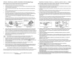
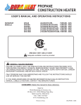
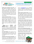
Kozy-World
®
GAS-FIRED INFRARED
OUTDOOR SPACE HEATER
USER’S INSTALLATION, OPERATION AND
MAINTENANCE MANUAL
MODEL : KPH120 (PROPANE, 11,000 BTU/HR)
FOR YOUR SAFETY
If you smell gas :
1. Shut off gas to the appliance.
2. Extinguish any open flame.
3. If odor continues, immediately call your gas
supplier.
FOR YOUR SAFETY
Do not store or use gasoline or other flammable
vapors and liquids in the vicinity of this or any
other gas appliance.
WARNING! For outdoor use only.
Ø INSTALLER : LEAVE THIS MANUAL WITH THE CONSUMER
Ø CONSUMER : RETAIN THIS MANUAL FOR FUTURE REFERENCE
TABLE OF CONTENTS
PAGE NO.
1
.
General Safety Instructions
.
Heater Assembly Instructions
2
.
Self Contained Propane Systems
2
.
Gas Supply Connection
3
.
Locating Your Heater
3
.
Clearance to Combustibles
3
.
Lighting
3
.
Shutdown & Storage Instructions
4
.
Maintenance
4
.
Main Burner Removal & Installation
4
.
Test Firing Heater
5
.
Alternate Gas Supply Systems
5
.
Troubleshooting
6
.
Parts List
7
.
Warranty Information
8
CALIFORNIA PROPOSITION 65 WARNING
Fuels used in gas or oil-fired appliances and the
products of combustion of such fuels, contain
chemicals known to the State of California to
cause cancer, birth defects and other reproductive
harm. California Health & Safety Code Sec
25249.6
IMPORTANT:
WARNING
Improper installation, adjustment, alteration, service or maintenance can cause injury or property
damage. Read the installation, operating and
maintenance instructions thoroughly before
installing or servicing this equipment.
Read this user’s manual carefully and completely before using. Serious injury or death
from burns, fire, explosion and/or carbon monoxide poisoning can result from improper
use.
IMPORTANT SAFETY PRECAUTIONS :
• Children and adults should be alert to high surface temperature around the burner assembly and heat reflector
when operating this heater.
• Children should be carefully supervised, when they are
in the area of the patio heater.
• Always maintain proper clearance from combustible
materials. Minimum clearance from combustibles :
Side 10”; Ceiling 12”; Rear 10”; and Below 30”.
• Any cleaning agent used on the heater should be of a
non-corrosive and non-combustible type.
• The stainless steel emitter screen and gas valve normally do not require cleaning and should never be painted.
The reflector and control cover may be cleaned but
never painted.
• Propane cylinder must be disconnected when the heater
is not in use.
• Never refill disposable propane cylinders.
• Heater must be placed on a level and secure surface and
shall be readily accessible.
• Do not use in high winds or when lightening is present.
• Never hang anything including clothes or other flammable items on the heater.
PRODUCT FEATURES
• Do not operate this heater unless it is completely assembled with reflector and guard grill in place.
• Adequate clearance around air openings into the combustion chamber, provisions for accessibility and for
combustion and ventilation air supply must be maintained at all times when the heater is operating.
• The heater should be inspected before initial use and at
least annually by a qualified person. More frequent
cleaning may be required as necessary. It is imperative
that the control compartment, burner and circulating air
passages of the heater be kept clean.
• Never connect heater to an unregulated gas supply.
• The heater is shipped from the factory for propane gas.
This heater is for use with propane gas only, do not convert heater to any other gas.
• A minimum supply pressure of 11” water column is
required for the purpose of input adjustment. Any
replacement regulator must be UL listed. The minimum
inlet pressure to the regulator from the gas tank is 5 psi
and maximum pressure is 150 psi.
.
.
.
.
.
Self Contained
Lightweight and Moveable
Integral/Positive Piezo Igniter
Safety Tip-Over Shutoff System
Uniformly Distributed Heat Pattern
UNPACKING :
1. Remove heater, reflector and guard grill from carton.
2. Remove all protective packaging applied to heater parts
for shipment.
3. Retain carton and packing material until heater is operated and found in good condition.
Check heater for any shipping damage. If
any of the parts show any external or internal
damage or if there is a part missing please
call 1-800-776-9425 for a free replacement.
DO NOT RETURN HEATER TO PLACE
OF PURCHASE.
• Do not move the heater while in operation. Always
allow heater to cool completely before moving.
• This heater is designed for heating purposes only and
should never be used for cooking.
• All gas connections should be checked for leaks utilizing a soap solution. Never use a flame for gas leak
checks.
1
SPECIFICATIONS
22”
HOW TO ASSEMBLE
STEP #1
STEP #4
STEP #2
36”
STEP #5
STEP #3
13.9”
MODEL NO.
RATING
GAS
MIN INLET SUPPLY
PRESSURE
MANIFOLD PRESSURE
SIZE
WEIGHT
KPH120
11,000 BTU/hr
PROPANE
11” WC
10.7” WC
21.8” x 36”
7.5 lbs. (3.4 kg)
SELF CONTAINED PROPANE (LP)
GAS SYSTEM :
The self contained gas system for this mini patio heater is designed to be used with a 16.4 oz. Propane gas
cylinder (disposable). Gas cylinder must be constructed and marked in accordance with specifications of the
U.S. Department of Transportation for Propane Gas Cylinders.
➺ NEVER REFILL DISPOSABLE CYLINDERS.
2
CYLINDER ATTACHMENT TO
HEATER :
• Turn gas control knob clockwise to “ OFF”
CYLINDER REMOVAL :
• Lift and rotate propane cylinder as shown in Fig. 6.
Disconnect cylinder by turning it counter clockwise.
• Remove base assembly door as show in Fig. 1.
Lift and rotate gas pressure regulator outwards
as show in Fig. 2.
Fig. 5
Fig. 6
LOCATION – FOR OUTDOOR USE ONLY:
• This outdoor patio heater is designed primarily for
temporary heating of outdoor areas such as patios, spas,
work areas and outdoor construction sites.
Fig. 1
• The installation of your patio heater must conform with
local codes or, in the absence of local codes, with the
latest edition of National Fuel Code ANSI Z223.1. In
Canada, installation must conform to the current
CAN1-B149 INSTALLATION CODE.
• The minimum clearances to combustible materials
(shown below) must be maintained at all times.
CEILING/OVERHANG
12”
10”
Fig. 2
• Attach cylinder to regulator inlet fitting by turning
cylinder clockwise as shown in Fig. 3. Push and rotate
gas cylinder downwards as shown in Fig. 4, till it is
vertically centered in the base assembly as shown in
Fig. 5.
30”
LIGHTING INSTRUCTIONS :
Fig. 3
Fig. 4
1. Turn gas control knob clockwise to “ OFF” position.
2. Remove base assembly door.
3. Connect propane ( disposable) cylinder to regulator inlet.
4. Push in and turn gas control knob counter clockwise to “ IGN/ON” until you hear the igniter click.
Pilot should light. This will light the burner. If needed,
keep pressing and turning the control knob counterclockwise
until the burner lights.
3
5. Keep the control knob depressed for at least 30
seconds after lighting burner. After 30 seconds release
control knob.
6. If burner does not stay lit, repeat steps 4 & 5.
7. When burner is lit, turn gas control knob counterclockwise to desired setting.
8. Replace base assembly door.
RELIGHTING :
a) Turn gas control knob clockwise to” OFF “ position.
b) Wait 5 minutes before attempting to relight burner.
c) Repeat sets 4 & 5.
SHUTDOWN INSTRUCTIONS :
SAFETY :
BEWARE
OF SPIDERS!
CAUTION : BURNER TUBES MUST
BE INSPECTED & CLEANED BEFORE
FIRSTUSE.
Spiders and small insects occasionally spin webs or make nests in
the burner tubes and/or orifices during warehousing and transit.
These webs or nests can lead to a gas flow obstruction, which
could result in a fire in and around the burner tubes. This type of
fire is known as FLASH BACK and can cause serious damage to
your patio heater and create an unsafe operating condition for the
user. Although an obstructed burner tube is not the only cause of
FLASH BACK, it is the most common cause, and frequent
inspections and cleaning of the burner tubes is necessary.
1. Turn gas control knob clockwise to “ OFF “ position.
2. Remove base assembly door.
3. Disconnect propane cylinder and replace base assembly
door.
NOTICE : White smoke may appear around the emitter
screen during the first few minutes of the initial use. This
is not a defect and will go away shortly.
STORAGE :
Never store a propane gas cylinder inside a building or in
the vicinity of any gas or oil burning appliance. Cylinder
must be disconnected and removed from the heater base
assembly and stored outdoors in a well ventilated area out
of reach of children, in accordance with the standard for
the storage and handling of liquefied gasses ANSI/NFPA
58-latest edition. The plastic cap supplied with propane
cylinder must be tightly installed when the cylinder is disconnected from the heater.
The manufacturer recommends annual inspection and
cleaning of the combustion and ventilation air passageways of the heater, burner, burner venturi and main burner
orifice at least once a year or immediately upon indication
of any of the following symptoms:
• Flash back
• Smell of aldehyde together with yellowish flames
• Excessive popping noise
• Diminished and uneven emitter glow
The stainless steel emitter screen normally does not
require cleaning and should NEVER be painted. The
reflector may be cleaned, but never painted. Other painted portions (post, base assembly) of the heater may be
recoated only with high temperature (1200˚F) paint.
NOTE : Installation of optional 20 lb. cylinders
and any repairs should be done by a qualified service person.
MAIN BURNER REMOVAL &
INSTALLATION PROCEDURE :
NOTE : HEATER SURFACE TEMPERATURE MUST
BE COLD BEFORE INITIATING BURNER
REMOVAL.
4
BURNER
ASSEMBLY
REMOVAL
:
TEST FIRING HEATER :
• Remove reflector and emitter screen as an assembly by
removing the screws that fasten the emitter screen to the
emitter support pan.
Test fire your patio heater, following the lighting instructions applicable to the gas control system employed.
• Remove base assembly door. Disconnect the gas supply
line and thermocouple wire from the gas control valve.
Leak test all gas connections with soap solution. Soap
bubbles indicate gas leakage. DO NOT use a match or
flame to test for gas leaks.
• Remove two screws which hold the burner bracket and
disconnect ignition wire from the electrode and remove
the main burner assembly.
Emitter Assembly
Mounting Screws
Burner Assembly
Burner Bracket
Post
Alternate Propane System : Could be connected to a
20 lb. Propane (LP) gas cylinder, providing the gas
system is installed by a qualified service person. Gas
cylinder must be constructed and marked in accordance
with specifications of the U.S. Department of
Transportation for Propane Gas Cylinders and must also
be equipped with the following :
• A collar to protect the propane gas valve.
Gas Control
Cylinder Enclosure
• A shutoff valve terminating a propane gas cylinder
valve outlet QCV-Type 1.
• A safety relief valve having direct contact with the
vapor space of the tank.
• An arrangement of vapor withdrawal.
h
• An approved hose and adapter must be used without
alteration.
Any spider webs, nests or debris can be cleaned with a
straight piece of wire and wire brush.
• Turn heater gas control knob and gas cylinder valve to
“ OFF” position.
You may use a vacuum cleaner. Never use wood or plastic toothpicks to clear ports or other openings, because
wood and plastic can break and block the ports.
BURNER ASSEMBLY INSTALLATION :
Install the burner assembly by reversing the aforementioned burner assembly removal. Upon completion of
burner assembly installation, make sure it is in the center
of the emitter support pan. Now install and secure the
emitter and reflector assembly.
After reassembly, check the burner gas connection for
leaks and then test fire heater. Observe the main burner
flame pattern. It should appear as shown in the following
figure and the flame color should be blue with slight yellow tipping. If flames extend more than 1/2 inch beyond
surface of the emitter screen or black soot is accumulating
on the emitter screen, the heater should be turned off
immediately. The heater should not be operated again
until repairs are made by a qualified service person.
2”
1”
0”
• Propane cylinder equipped with the new style QCV
valve is equipped with right handed threads.
• Propane cylinders have a bleed-off valve. This valve
should be inspected for leaks after each filling of the
cylinder. Turn clockwise to reseal.
• Fasten full propane cylinder to a table beneath the patio
heater and connect an approved hose and adapter
assembly to cylinder valve and heater regulator inlet
fitting by turning clockwise.
With heater gas valve still in the “OFF” position, turn ON
tank valve and check for leaks with soap solution.
A LP Cylinder enclosure, if provided by the consumer, must
conform to the following:
a. One side of the enclosure shall be completely open; or
b. For enclosure having four sides, a top and a bottom, shall
have at least two openings at cylinder valve level and two
openings at floor level and not less than a total free area of 10
square inches at valve level and floor level. Every opening
shall have minimum dimensions so as to permit the entrance
of a 1/8 inch diameter rod.
c. Cylinder valves shall be readily accessible for hand
operation. A door on the enclosure is acceptable.
d. A minimum clearance of 2 inches between the lower surface
of the floor of the Lp gas supply cylinder enclosure and the
ground.
e. Secure the gas cylinder with strap.
5
TROUBLESHOOTING
Problem
Burner won’t light
Possible Cause
• Control knob not in IGN/ON position
• Turn control knob to IGN/ON position
• Control knob not pressed in while
in IGN/ON position
• Air in the gas line
• Press in control knob while in IGN/ON
position
• Purge gas lines and repeat ignition
operation.
• Replace cylinder
• Clean burner orifice
• Service by a qualified service
technician
• Low gas pressure
• Burner orifice clogged
• Blockage in gas line
Ignitor did not spark:
• Ignitor cable not connected to ignitor
• Igniter electrode positioned wrong
• Ignitor electrode broken
• Ignitor wire pinched or broken
Burner won’t stay lit
Emitter glow is uneven
What To Do
• Control knob not pressed in long
enough
• Burner flame not touching the
thermocouple
• Thermocouple damaged or
connection loose at gas control
• Bad gas valve
• Corrosion of thermocouple contact
• Bad thermocouple
• Tilt switch in trip angle/OFF position
• Heater not level
• Burner tilted
•
•
•
•
Connect cable to ignitor
Correct electrode position
Replace electrode
Free ignitor cable, if damaged
replace the assembly
• After burner lights, keep control knob
pressed in for 60 seconds
• Clean pilot assembly
• Tighten connection or replace
thermocouple
• Service by qualified service technician
• Clean thermocouple contact
• Service by qualified service technician
• Reset tilt switch reset angle/On
position by tilting heater
• Level heater
• Go to burner removal & installation
procedure. Straighten burner
Call 1-800-776-9425 for Technical Assistance
6
PARTS LIST
NO.
1
2
3
4
5
6
7
8
9
9-1
10
11
12
12-1
13
14
14-1
15
16
17
18
19
20
21
22
23
24
25
26
27
28
29
30
31
32
33
34
35
36
37
38
39
40
DESCRIPTION
Reflector
Cap Nut
Flat Washer
Flat Washer
Hexa Nut
Hexa Bolt
Emitter Ass’y
Burner Ass’y
Thermocouple
Thermocouple Wire
Venturi Ass’y
Screw
Emitter Lower
Machine Screw
Guard Ass’y
Spark Plug
Spark Plug Wire
T/C Clip
Screw
Countersunk Head Screw
Screw
Post
Nozzle
Nozzle Holder
Stiker
Tubing Outlet Ass’y
Tubing Outlet Screw
Screw
Base Upper
MPU Lead Wire
Valve
Regulator Ass’y
Supporter Pin
E-Ring
Spiral Ring
Regulator Supporter
Base
Leg
Knob Ass’y
Tapping Screw
Tip Over S/W
Connector Ass’y
Base Door
PART NO.
2PHP001
2PHZ002
2PHZ004
3DSA002
3PHZ005
3PHP002
M4X10
1PHW001
4D0023
4PHS001
3PHT016
RCM02G
RCD01A
3PHT008
RCM08A
1PHI002
4PHH008
DMV100P
3PHZ017
4PHM002
4PHS003A
3PHP012A
OPHI001
4PHR005
3PHZ015
3PHZ013
2PHI006
QTY.
1 EA
3 EA
6 EA
6 EA
3 EA
3 EA
1 EA
1 EA
1 EA
1 EA
3 EA
1 EA
3 EA
2 EA
1 EA
1 EA
3 EA
2 EA
3 EA
1 EA
1 EA
1 EA
1 EA
1 EA
1 EA
4 EA
1 EA
1 EA
1 EA
1 EA
1 EA
2 EA
1 EA
1 EA
1 EA
3 EA
1 EA
2 EA
1 EA
1 EA
1 EA
7
LIMITED WARRANTY
This limited warranty is extended to the original retail purchaser of this heater and warrants against any defect in materials and
workmanship for a period of 1 year from the date of retail sale. World Marketing of America, Inc., at it’s option will either provide
replacement parts, replace or repair the unit, when properly returned to us. (shipping costs, labor costs, etc. are the responsibility of
the purchaser)
DUTIES OF THE OWNER:
This heating appliance must be operated in accordance with the written instructions furnished with this heater. This warranty shall
not excuse the owner from properly maintaining this heater in accordance with the written instructions furnished with this heater. A
bill of sale, canceled check or payment record must be kept to verify purchase date and establish warranty period. Original carton
should be kept in case of warranty return of unit.
WHAT IS NOT COVERED:
1. Damage resulting from use of improper fuel.
2. Damage caused by misuse or use contrary to the owners manual and safety guidelines.
3. Damaged caused by lack of normal maintenance.
4. Use of non-standard parts or accessories.
5. Damage caused in transit.
Freight charges on warranty parts or heaters to and from the factory shall be responsibility of the owner.
This warranty does not imply or assume any responsibility for consequential damages that may result from the use, misuse or the
lack of routine maintenance of this heating appliance. A cleaning fee and the cost of parts may be charged for a appliance failures
resulting from lack of maintenance. This warranty does not cover claims which do not involve defective workmanship or materials.
THIS LIMITED WARRANTY IS GIVEN TO THE PURCHASER IN LIEU OF ALL OTHER WARRANTIES. EXPRESSED OR
IMPLIED, INCLUDING BUT NOT LIMITED TO THE WARRANTIES OF MERCHANTABILITY OF FITNESS FOR A PARTICULAR PURPOSE. THE REMEDY PROVIDED IN THIS WARRANTY IS EXCLUSIVE AND IS GRANTED IN LIEU OF ALL
OTHER REMEDIES. IN NO EVENT WILL WORLD MARKETING OF AMERICA BE LIABLE FOR INCIDENTAL OR CONSEQUENTIAL DAMAGES.
Some states do not allow limitations on how long an implied warranty lasts, so the above limitation may not apply to you. Some
states do not allow the exclusion or limitation of incidental or consequential damages of the above limitation or exclusion may not
apply to you.
CLAIMS HANDLED AS FOLLOWS:
1. Contact us at 1-800-776-9425. Do not return the heater to place of purchase.
2. Write or email our Warranty Dept., noting the heater model, the problem, copy of the sales receipt or date or purchase.
Send letter to the attention of “Warranty Claims Administrator”.
3. DO NOT RETURN THE HEATER TO WORLD MARKETING OF AMERICA, INC. unless instructed to do so by our
Representative. This warranty gives you specific legal rights and you may also have other rights which vary from state to state.
DO NOT RETURN THE HEATER TO PLACE OF PURCHASE.
MODEL:
DATE OF PURCHASE:
PLACE OF PURCHASE:
__________________________________
__________________________________
__________________________________
Please complete and retain for your records.
World Marketing of America, Inc.
PO Box 192, Route 22 West, Mill Creek, PA 17060
Phone: 1-800-776-9425
Email: [email protected]
8