1
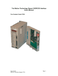
Trio Motion Technology Sigma II SERCOS Interface
Users Manual
Trio Product Code P730
Date
23rd Jan 2006
8th Sept 2003
6th Aug 2003
14th Feb 2003
10th Feb 2003
14th Nov 2002
Description
Description of the support for drive controlled homing
added in firmware version 0.0.14.
Absolute encoder support added – software version
0.0.9
Registration Support added.
Brief SERCOS Interface Specification description added
Support for Probe IDNs added
Initial Issue
Version
1.5
1.4
1.3
1.2
1.1
1.0
References
1. Specification SERCOS Interface, version 2.2 (November 2001)
2. Sigma II Series Users Manual Design and Maintenance, Manual Number:
SIE-S800-32.2D
Definitions and Abbreviations
AT
CP0,1,2,3,4
FO
MDT
MST
RTC
RTS
SERCOS
Telegram
:
:
:
:
:
:
:
:
:
Amplifier (slave drive ) Telegram
SERCOS Communication Phase 0,1,2,3,4
Fibre Optic
Master Data Telegram
Master Synchronisation Telegram
MDT Real Time Control Bit
AT Real Time Status Bit
SErial Real-time COmmunication System Interface
communication message
Introduction
This document describes the specification of the Sigma II SERCOS Interface, its
compliance with the SERCOS specification, and the procedures for commissioning
the module.
The SERCOS interface uses optical data transmission between control units and
drives. The Sigma II SERCOS Interface provides a SERCOS network interface for
the Yaskawa Sigma drives.
Please see reference (1) for further information concerning the SERCOS Interface
Specification, and (2) for further information about the Sigma drives.
Front Panel Specification
The front panel contains the SERCOS communication phase and error status
LEDs, the network baud rate and intensity switches, the drive address rotary
switches, the SERCOS network loop error LED and the SERCOS FO connectors.
It is necessary to cycle power to the drive after changing any switch positions
before the new values will be used.
Drive SERCOS Baud Rate
DIP switches 1 and 2 are used to select the SERCOS baud rate, and should be set
according to the following table:
Switch 1
OFF
ON
OFF
ON
Switch 2
OFF
OFF
ON
ON
Baud rate
2 Mbps (default)
4 Mbps
8 Mbps
16 Mbps
Drive SERCOS optical output adjust
DIP switches 3,4, and 5 are used to select the fibre optic light intensity level, and
should be set according to the following table:
Switch 3
OFF
ON
OFF
ON
OFF
ON
OFF
ON
Switch 4
OFF
OFF
ON
ON
OFF
OFF
ON
ON
Switch 5
OFF
OFF
OFF
OFF
ON
ON
ON
ON
Intensity level
0 (HZ TX output)
1 (low)
2
3 (default)
4
5
6 (high)
7 (not used)
Test Mode
DIP switch 6 is used to select a test mode. If this switch is set to on when the
drive is powered on, the SERCOS Interface module will enter the ‘zero bit stream’
test mode. Whilst the module is in this test mode the red fault LED will flash. To
return to normal operating mode, switch 6 must be set to the off position and the
drive power cycled.
Drive Address Rotary Switches
The two hexadecimal rotary switches are used to set the drive SERCOS network
address (0 to 254). The most significant hex digit is set by the ‘16x’ switch, and
the least significant by the ‘1x’ switch. Each drive on the SERCOS network must
have a unique address.
MS Switch
LS Switch
0
0
0
1
0
2
.
.
.
.
.
.
.
.
.
.
F
D
F
E
F
F
*Reserved for repeater use only.
**Not allowed for SERCOS drive address.
SERCOS address
0*
1
2
.
.
.
.
.
253
254
255**
Phase and Drive Status LEDs
The communication phase and error status LEDs indicate in which phase the drive
is operating, and whether it has identified an error. The drive phase shall be the
same as the network phase, unless the drive has identified an error and reset to
CP0. All three green LEDs shall be illuminated when in CP4, and shall remain on
permanently if the drive is enabled, or flash if the drive is not enabled.
Indicator
Top right green LED
Top left green LED
Bottom right green LED
Bottom left red LED
CP0
ON
OFF
OFF
X
CP1
OFF
ON
OFF
X
CP2
ON
ON
OFF
X
CP3
OFF
OFF
ON
X
CP4
ON(blink)
ON(blink)
ON(blink)
X
Enable
ON
ON
ON
X
ERROR
X
X
X
ON
SERCOS Loop Error LED
The RED LED is ON if there is a distortion problem or if the fibre optic loop is
open.
SERCOS Interface Specification
The SERCOS Specification defines a real-time optical serial communication
standard between a single master and one or more slave drives on a network
ring, transmitting periodic and non-periodic control and status information.
During initialisation the operation of the network is defined by the master
according to the performance capabilities of itself and that of the slaves on the
network.
Following power-on, the network passes through several states (communication
phases (CP)) before reaching the normal operating state (phase 4). Default
timing parameters are used in the first 3 states, during which the master
transmits configuration information to each slave drive.
The communication phases are:
CP0 – The master starts to transmit the periodic synchronization clock telegram
(MST), which is repeated by each drive in the ring after it has successfully
completed its power-on initialisation. The master is able to determine the network
ring has been closed when it simultaneously receives its transmitted MST
message. The master moves the ring to phase 1 after ensuring the ring has been
successfully closed.
Each SERCOS communication cycle starts with the MST which is received by all
slave drives concurrently. This message is used to synchronize the telegram
transmission times within the cycle, and the slave drives internal processing and
control loops. The MST also identifies the required ring phase.
CP1 – During CP1 and CP2 the master addresses each drive individually, via a
telegram (MDT) message containing a single data record with control information
for the slave being addressed. The slave will transmit a telegram (AT) message
containing status information in reply, only when it is ready to move to phase 2.
Hence, the master addresses each drive in the ring until it has a valid response
and is able to determine the ring is ready to move to phase 2.
CP2 – In this phase the master transmits communication (telegram transmission
times and timeslots) and the cyclic transmission configuration parameters (used
in phases 3 and 4). The drive configuration parameters may be transmitted
during this or phase 3.
Having configured all the drive communication parameters, the master sends the
procedure command ‘CP3 transition check’ to each drive. The drives run internal
checks to ensure they have received all the information required to operate in
phase 3. After each drive has responded with the ‘procedure command correctly
executed’, the master moves the ring into phase 3.
CP3: In phase 3 the master and all the slaves in the ring transmit their respective
telegram messages every cycle time, using the timeslot information received in
the previous phase. The master telegram (MDT) now contains a data record for
each slave in the ring, enabling the master to exchange information with each
drive simultaneously. Hence, it is possible to configure all the drives in the ring in
a more time efficient manner.
Before moving the phase 4, the master sends the procedure command ‘CP4
transition check’ to each drive, which runs internal checks to ensure it has
received all the information it requires to operate in phase 4. After every drive
has responded with the ‘procedure command correctly executed’, the master
moves the ring into phase 4.
CP4: Phase 4 is the normal operating state of the ring. Every cycle time the
master transmits control information to each drive in the ring, which responds
with its status – including motion feedback information. The master is now free to
enable the drives and send positioning information.
See ref(1) for further information about the SERCOS Interface Specification.
Installation and Commissioning
Set the required SERCOS network drive address, baud rate and intensity using
the front panel switches (refer to Front Panel Specification section).
During CP2 the SERCOS network master must write the timing parameter IDNs
for the cyclic phases (CP3 & CP4) to the drive.
SERCOS IDN
Description
00002
00006
00089
00009
00010
00015
SERCOS interface cycle time
AT transmission starting time
MDT transmission starting time
Position of data record in MDT
Length of MDT
Telegram Type Parameter
If all the parameters in the above table are not configured during CP2 the Sigma
II Interface will not pass the CP3 transition check (IDN 127).
Drive Configuration
The drive will operate in position, velocity, or velocity with torque feed forward
control modes, using the standard or appropriately defined application telegrams.
To use the velocity (V-REF) with torque feed forward (T-REF) control mode the
drive’s operation mode and telegram configuration SERCOS parameters should be
configured as given in the table below.
IDN
IDN Description
Value
Notes
00015
00024
00032
Telegram type
MDT Configuration List
Primary Mode of
Operation
7
36,80
2
Application Telegram
Velocity & torque command values
Velocity control mode
The drive parameters Pn000.1 should be set to 9 (speed control method),
Pn002.0 should be set to 2 (T-REF used for torque feed forward), and Pn400
(torque feed forward gain) should be a non-zero value.
SERCOS Interface Specification Conformance
The Sigma II Interface module satisfies SERCOS Interface Specification
compliance class B in velocity or position control mode, and can run at SERCOS
cycle times of 500usec and above. It does not currently support the class B drive
controlled homing procedure IDNs.
SERCOS data transmissions occur in regular cycles. The cycle timing is controlled
by the SERCOS master, which transmits a Master Synchronization Telegram
(MST) at the start of each cycle. When the ring is up and running, the drives will
each transmit an Amplifier Telegram (AT) to the master, and finally the Master
will transmit its Data Telegram (MDT) which contains information for each drive.
MST-AT is t1(IDN6)
MST-MDT is t2(IDN89)
MST-MST is tscyc (IDN2)
After MDT to MST is tmtsy (IDN88)
A summary of the SERCOS IDNs supported by the Sigma II Interface is shown in
the table below, and a more complete discussion of these IDNs appears in
Appendix A. The compliance column indicates which SERCOS interface
specification compliance class the parameter belongs and the control mode
(position, velocity or torque) where appropriate. The comments indicate whether
the network master has read only (R) or read-write (RW) access.
IDN
00001
00002
00003
00004
00005
00006
00007
00008
00009
00010
00011
00012
00013
00014
00015
00016
00017
00018
Description
Control Unit Cycle Time
Communication Cycle
Time
Shortest AT transmission
starting time
Transmit/receive
transition time
Minimum feedback
processing time
AT transmission starting
time
Feedback acquisition
capture point
Command value valid
time
Position of data record in
MDT
Length of MDT
Class 1 Diagnostic
Class 2 Diagnostic
Class 3 Diagnostic
Interface Status
Telegram Type
AT Configuration List
IDN-list of all operation
data
IDN-list of operation data
for CP2
Abbreviation
Compliance
Comment
tNcyc
tScyc
B (position)
A
RW
t1min
A
R
tATMT
A
R
t5
B
R
t1
A
RW
t4
B
RW
t3
B
RW
A
RW
A
A
B
B
A
A
C
A
RW
R
R
RW
RW
R
A
R
C1D
C2D
C3D
00019
00021
00022
00024
00025
00028
00029
00030
00032
00033
00036
00040
00043
00044
00047
00051
00052
00055
00057
00076
00080
00084
00085
00086
00087
00088
00089
00090
00091
00092
00095
00096
00097
00098
00099
00104
00124
00125
00127
00128
00138
00140
00141
IDN-list of operation data
for CP3
IDN-list of invalid
operation data, CP2
IDN-list of invalid
operation data, CP3
MDT Configuration List
IDN-list of all procedure
commands
MST error counter
MDT error counter
Manufacturer Version
Primary operation mode
Secondary operation
mode 1
Velocity command value
Velocity feedback value
Velocity polarity
parameter
Velocity data scaling type
Position command value
Position feedback value
Reference distance 1
Position Polarity
parameter
Position window
Position data scaling type
Torque command value
Torque feedback value
Torque polarity parameter
Torque/force data scaling
type
Transmit to transmit
recovery time
Receive to receive
recovery time
MDT transmission starting
time
Command value
proceeding time
Bipolar velocity limit value
Bipolar torque limit value
Diagnostic Message
Slave Arrangement
Mask Class 2 diagnostic
Mask Class 3 diagnostic
Reset class 1 diagnostic
Position loop Kv factor
Standstill window
Velocity threshold
CP3 transition check
CP4 transition check
Bipolar accel limit value
Controller type
Motor type
A
R
A
R
A
R
C
A
RW
R
A
A
C
A
B
R
R
R
RW
RW
B (velocity)
B (velocity)
B (velocity)
RW
R
RW
B
B
B
B
B
(velocity)
(position)
(position)
(position)
(position)
RW
RW
R
RW
RW
B
B
B
B
B
B
(position)
(position)
(torque)
(torque)
(torque)
(torque)
RW
RW
RW
R
RW
RW
SLKN
A (1)
R
tMTSY
A
R
t2
A
RW
tMTSG
B
R
B (velocity)
B (torque)
A
A
B
B
A
B (position)
B (velocity)
B (velocity)
A
A
B
N/A
N/A
RW
RW
R
R
RW
RW
RW
RW
RW
RW
RW
RW
RW
R
R
nx
00142
00143
00150
00157
00159
00160
00181
00187
00188
00189
00206
00207
00390
Application type
SERCOS Interface version
Reference offset 1
Velocity window
Monitoring window
Acceleration data scaling
type
Manufacturer Class 1
Diagnostics
IDN List of Configurable
Data in the AT
IDN List of Configurable
Data in the MDT
Following Distance
Drive on delay time
Drive off delay time
Diagnostic Number
A
A
B (position)
B (velocity)
B (position)
B
R
R
RW
RW
RW
RW
N/A
R
C
R
C
R
B (position)
B
B
N/A
R
RW
RW
R
Notes
(1) Only for slaves with several drive addresses
Reading and Writing Yaskawa Drive Parameters
The Yaskawa drive parameters are accessible via the SERCOS network – drive
parameter numbers 0 and above map to SERCOS parameter numbers 32768
(0x8000) and above in two blocks:
Drive parameter
0..0x4FFF
0x8000..0x8FFF
Sercos IDN:
0x8000..0xCFFF
0xD000..0xDFFF
Please refer to your Yaskawa drive User’s Manual (Ref. 2) for further information
about these parameters.
From Trio BASIC the parameters can be read using the SERCOS command once
the SERCOS ring has been initialised to phase 2.
SERCOS(4,slot#,drive address#,parameter#) – Read a drive parameter
SERCOS(5,slot#,drive address#,#format,parameter#) – Write a drive parameter
Registration (Probe) Support
(Requires firmware 0.0.8 and Motion Coordinator V1.6223 or later)
The drive has the ability to latch a position either on the motor z-mark or a rising
or falling edge received via an external input. The SERCOS and drive parameters
must be configured as shown in the tables below to enable this functionality on
the drive. SERCOS IDNs are used to set/reset the latch and read the latched
position. These IDNs are reflected in the MDT Real Time Control Bit, AT Real Time
Status Bit and the second parameter in the AT data record – hence the latch
functionality can be controlled via cyclic SERCOS data.
To enable the cycle data response, the AT telegram must be configured as an
application telegram with two parameters, the second being the probe latched
position IDN (either 130 for a rising edge or 131 for a falling edge). On a Motion
Coordinator, the axis type must be set to 22 – to enable velocity control with
latch functionality.
When the latch has triggered the AT RTS1 and IDN401 are set, and the latched
value will be stored in IDN 130 or 131 depending upon the trigger edge. The z
mark does not have a trigger edge, but is configured as per the external rising
edge.
The external trigger uses the drives EXT3, input via connector CN1 pin 46.
SERCOS Parameters
IDN
Value
Description
301
405
305
409 or 410
169
1 or 2
Master Telegram’s Real Time Control Bit 1 to be
reflected into IDN405 – the Probe 1 Enable/Disable
control IDN.
The Drive Telegram’s Real Time Status Bit 1 to reflect
the status of either the Probe 1 rising edge or falling
edge latch status IDN.
The probe control parameter is set to trigger the probe
on either a rising (1) or falling (2) edge. This will
determine in which IDN the latched value is stored –
either IDN 130 for a rising edge or 131 for a falling
edge.
Drive Parameters – Z mark trigger
Pn
Value
$511
0x8888
Description
Drive Parameters – External Input
Pn
Value
Description
$511
0xF888 or
0x6888
0xXXX1
To trigger on a rising (0xF888) or falling (0x6888)
edge.
Enables free allocation input signals. The X is a don’t
care.
$50A
Note that drive parameter Pn511 is accessed by using SERCOS IDN (32768 +
0x511) since it is classed as a product (or manufacturer) specific IDN.
P730 Parameters
IDN
Value
Description
49252
0 or 3
Configures the latch input, either the z-mark (0) or
external input (3).
Example TrioBASIC program files.
The following file can be run to configure the drive parameters. Note that power
must be cycled to the drive after setting these parameters.
IF trig_mode = z_mark THEN
SERCOS(5,nslot,ndrive,32768+$511,2,$8888)
SERCOS(5,nslot,ndrive,32768+$50A,2,$8100)
SERCOS(5,nslot,ndrive,32768+$50B,2,$6548)
ELSEIF trig_mode=external_input THEN
IF trig_edge = high THEN
'Active high - rising edge.
SERCOS(5,nslot,ndrive,32768+$511,2,$F888)
ELSE
'Active low - falling edge.
SERCOS(5,nslot,ndrive,32768+$511,2,$6888)
ENDIF
SERCOS(5,nslot,ndrive,32768+$50A,2,$8881)
SERCOS(5,nslot,ndrive,32768+$50B,2,$8888)
ELSE
‘Error
ENDIF
At each power-up, the following file must then be run to configure the SERCOS
parameters. This file must agree with the drive settings (above) as regards
rising/falling edge. Subsequently, the TrioBASIC REGIST(1) command can be
used to set and enable the latch, MARK used to identify when the latch has
triggered, and REG_POS to read the latched value. These commands use the
SERCOS cyclic data.
‘RTC1 to update IDN 405 (Probe 1 enable/disable)
SERCOS(5,nslot,ndrive,301,2,405)
' IDN 305 : RTS Bit 1 : to trigger on probe 1 latch - either high or
low status
' IDN 169 : Probe Control Parameter - Set active edge which
determines which
' idn the recorded probe value will be stored in (either 130 high or
131 low).
IF trig_edge = high THEN
SERCOS(5,nslot,ndrive,305,2,409)
SERCOS(5,nslot,ndrive,169,2,1)
'ensure idn 130 is second parameter in AT telegram.
ELSE
SERCOS(5,nslot,ndrive,305,2,410)
SERCOS(5,nslot,ndrive,169,2,2)
'ensure idn 131 is second parameter in AT telegram.
ENDIF
'Set probe trigger input on drive.
SERCOS(5,nslot,ndrive,49252,2,trig_mode)
The TrioBASIC registration functions can be used in the usual way except that the
mode cannot be changed from the one initialised. I.e. if external input falling
edge was selected and set up in the drive, this will always be the registration
mode for the axis. The actual value of n placed in the REGIST(n) command
therefore does not matter. (it is not used by the function)
Here is a typical TrioBASIC registration sequence:
' Arm the registration function
REGIST(1)
‘ wait for active registration event
WAIT UNTIL MARK
‘ obtain the captured (probe) position
captured_posn = REG_POS
Absolute Encoder Support
(Requires firmware 0.0.9 and Motion Coordinator V1.6226 or later)
The number of absolute turns may be read on power up from absolute encoders
as drive parameter 0x8603. This is mapped to IDN 0xD603 (see - Reading and
Writing Drive Parameters). The absolute position within a turn can be obtained
from the motor position telegram. When using Trio BASIC this is best obtained
using the ENCODER axis parameter. The following program illustrates how the
absolute position can be obtained and loaded:
axis_num=6
ser_add=1
ser_slot=0
BASE(axis_num)
UNITS=1
REP_DIST=1000000000
' Check absolute encoder set to absolute mode:
IF SERCOS(4,ser_slot,ser_add,$8002)<>0 THEN PRINT "Not absolute
encoder"
' Type 273 is 17 bit absolute, 272 is 16 bit absolute
PRINT "Encoder Type:";SERCOS(4,ser_slot,ser_add,$d516)
turns=SERCOS(4,ser_slot,ser_add,$D603)
IF turns>32767 THEN turns=turns-65536
PRINT "Absolute Turns:";turns[0]
PRINT "Position within turn:";(ENCODER AND $1FFFF)[0]
' This example is for absolute 17 bit encoder:
DEFPOS(turns*131072+(ENCODER AND $1FFFF))
This sequence must be executed before the motor runs, as the number of turns is
not updated by the drive whilst the ENCODER value will change after the motor
moves. Consideration should be given to the size of numbers involved. If the
number of turns is high, the calculation for the DEFPOS statement can start to
lose accuracy.
Trio BASIC sequence to clear absolute backup alarm:
SERCOS(5,0,1,$a002,2,0) ' toggle display
SERCOS(5,0,1,$a000,2,$2001) ' Clear Alarm Command
SERCOS(5,0,1,$a001,2,$2) ' start process
SERCOS(5,0,1,$a001,2,$1) ' execute reset
Appendix A –SERCOS IDN Specification
IDNs 0-32767 are the standard SERCOS Interface Specification parameters.
IDNs 32768 and above are the Product specific (manufacturer) parameters.
Yaskawa drive parameters are mapped from this base number, hence drive
parameter 0 is SERCOS parameter 32768, and drive parameter 0x50A is SERCOS
parameter 34058 for example. SigmaII Interface parameters are mapped from
address 49152.
IDN S-0-0001 Control Unit (NC) Cycle Time (tNcyc)
Data Length
Data Type
Minimum Value
Maximum Value
Scaling/Unit
Read
Write
Default
2 Bytes
Unsigned integer
500
2000
usec
CP2-4
CP2
1000
The period at which the master control unit updates commands to the drive. The
drive automatically overrides this value with that of the Communication Cycle
Time (IDN 2) in CP3.
IDN S-0-0002 SERCOS Communication Cycle Time (tScyc)
Data Length
Data Type
Minimum Value
Maximum Value
Scaling/Unit
Read
Write
Default
2 Bytes
Unsigned integer
500
32000
usec
CP2-4
CP2
1000
The SERCOS (system interface) communication cycle time defines the period at
which the MST, AT & MDT telegrams are transmitted. Allowable cycle times are
500usec and from 1000usec to 32000 usec in 1000usec increments.
IDN S-0-0003 Shortest AT Transmission Start Time (t1min) – Read only
Data Length
Data Type
Minimum Value
Maximum Value
Scaling/Unit
Read
Write
2 Bytes
Unsigned integer
usec
CP2-4
N/A
Default
10
The minimum time the drive requires after receipt of the MST before it can send
its AT.
IDN S-0-0004 Transmit/Receive transition time (Tatmt) – Read only
Data Length
Data Type
Minimum Value
Maximum Value
Scaling/Unit
Read
Write
Default
2 Bytes
Unsigned integer
usec
CP2-4
N/A
10
The time the drive requires after completion of the AT transmission before
receiving the MDT. The master reads this parameter for all drives on the ring
during CP2 in order to calculate an appropriate MDT transmission starting time
(IDN 89).
IDN S-0-0005 Minimum Feedback Processing Time (t5) – Read only
Data Length
Data Type
Minimum Value
Maximum Value
Scaling/Unit
Read
Write
Default
2 Bytes
Unsigned integer
usec
CP2-4
N/A
150
The time required by the drive between the start of the feedback acquisition and
the end of the next MST – required for acquiring and processing cyclic feedback.
The master reads this value during CP2 in order to synchronize the measurement
times of the feedback acquisition capture point (t4 - IDN 7) appropriately for all
drives.
IDN S-0-0006 AT Transmission Starting Time (t1)
Data Length
Data Type
Minimum Value
Maximum Value
Scaling/Unit
Read
Write
Default
2 Bytes
Unsigned integer
IDN 3
IDN 2
usec
CP2-4
CP2
50
This value determines when the drive sends its AT during CP3 & CP4 (the time
interval after the MST). The value must be greater than or equal to the shortest
AT transmission starting time (IDN 3).
IDN S-0-0007 Feedback Acquisition Capture Point (t4)
Data Length
Data Type
Minimum Value
Maximum Value
Scaling/Unit
Read
Write
Default
2 Bytes
Unsigned integer
0
IDN 2
usec
CP2-4
CP2
See notes.
This value, determined by the master, is the time at which the drive feedback
must be acquired. In this way the master declares a default acquisition capture
point enabling synchronization of the feedback for all drives that work in
coordination with each other. The drive enables this point during CP3.
This value is automatically set to IDN 8.
IDN S-0-0008 Command Value Valid Time (t3)
Data Length
Data Type
Minimum Value
Maximum Value
Scaling/Unit
Read
Write
Default
2 Bytes
Unsigned integer
usec
CP2-4
CP2
See notes.
The time the drive accesses the new command values after the completion of an
MST. In this way the master provides the command value valid time to enable
synchronization of command values among all coordinated drives. The drive
enables this time during CP3.
This value is automatically set to Tscyc-150 usec in CP3.
IDN S-0-0009 Position of Data Record in MDT
Data Length
Data Type
Minimum Value
Maximum Value
Scaling/Unit
Read
Write
Default
2 Bytes
Unsigned integer
1 (one drive)
65,531
Bytes
CP2-4
CP2
None
This parameter holds the offset in bytes of the drive’s data record within the MDT.
It starts with ‘1’ for the initial data byte after the address field within the MDT.
The master informs each drive in the ring this value during CP2, and it becomes
active during CP3.
IDN S-0-0010 Length of MDT
Data Length
Data Type
Minimum Value
Maximum Value
Scaling/Unit
Read
Write
Default
2 Bytes
Unsigned integer
4 (one drive)
65,534 (number of bytes of 254 drives)
Bytes
CP2-4
CP2
None
This parameter holds the offset in bytes of the drive’s data record within the MDT.
It starts with ‘1’ for the initial data byte after the address field within the MDT.
The master informs each drive of this value during CP2, and it becomes active
during CP3.
IDN S-0-0011 Class 1 Diagnostics
Data Length
Data Type
Minimum Value
Maximum Value
Scaling/Unit
Read
Write
Default
2 Bytes
Binary
0
0xFFFF
CP2-4
N/A
None
The C1D identifies the current shutdown fault status of the drive. These errors
are latched into the C1D, and the C1D status bit (bit 13) is set in the drive status
word. These error flags are only cleared after the error has been eliminated and
the ‘Reset Class 1 Diagnostics’ procedure command (IDN 99) has been executed
via the service channel. When a fault occurs the drive decelerates to a stop and
releases torque.
Bit
0
1
2
3
4
5
6
7
8
Description
Overload fault
Amplifier over temperature fault
Motor over temperature fault
Cooling error
Control voltage fault
Feedback loss fault
Commutation fault
Over current fault
Over voltage fault
9
10
11
12
13
14
15
Under voltage fault
Power supply phase fault
Excessive velocity deviation
Communication interface fault
Software limit switch fault
Reserved
Manufacturer specific warning (see IDN 129)
Where 0 = no fault, 1 = fault.
IDN S-0-0012 Class 2 Diagnostics
Data Length
Data Type
Minimum Value
Maximum Value
Scaling/Unit
Read
Write
Default
2 Bytes
Binary
0
0xFFFF
CP2-4
N/A
0
The C2D identifies warnings of an impending drive shutdown error. When an
unmasked (see IDN 97) warning is activated or cancelled in the C2D, this sets (to
‘1’) the C2D change bit in the drive status. When the C2D is read via the service
channel, the C2D change bit is reset (to ‘0’). The warning bits in the C2D are not
latched, and hence are automatically reset when the warning condition is no
longer valid.
Bit
0
1
2
3
4
5
6
7
8
9
10
11
12
13
14
15
Description
Overload warning
Reserved: Amplifier over temperature warning
Reserved: Motor over temperature warning
Reserved: Cooling error warning
Reserved
Reserved: Positioning velocity exceeds limit
Reserved
Reserved
Reserved
Reserved: Under voltage warning (bus voltage)
Reserved
Reserved: Excessive velocity deviation
Reserved
Reserved: Target Position outside of travel range
Reserved
Manufacturer specific warning (see IDN 181)
Where 0 = no shutdown warning, 1 = shutdown warning.
IDN S-0-0013 Class 3 Diagnostics
Data Length
2 Bytes
Data Type
Minimum Value
Maximum Value
Scaling/Unit
Read
Write
Default
Binary
0
0xFFFF
CP2-4
N/A
0
This parameter contains the drive operation status flags. When a condition
changes in the drive, the corresponding bit changes in the C3D and - provided
the flag is not masked (see IDN 98) - the C3D change bit in the drive status is set
(to ‘1’). When the C3D is read via the service channel the C3D change bit is reset
(to ‘0’). These flags are not latched, and will be reset (to ‘0’) when the condition
no longer exists.
Bit
0
1
2
3
4
5
6
7
8
9
10
11
12
13
14
15
Description
Nfeedback = ncommand
Nfeedback = 0
Nfeedback < nx
T >= Tx (NYS)
T >= Tlimit
Ncommand > nlimit
In position
P >= Px (NYS)
Reserved
Nfeedback <= minimum spindle speed (NYS)
Nfeedback >= maximum spindle speed (NYS)
In coarse position (NYS)
Target Position Attained (NYS)
Interpolator Halted (NYS)
Reserved
Manufacturer specific warning (see IDN 182)
Where 0 = condition does not exist, 1 = condition exists.
IDN S-0-0014 Interface Status
Data Length
Data Type
Minimum Value
Maximum Value
Scaling/Unit
Read
Write
Default
2 Bytes
Binary
0
0xFFFF
CP2-4
N/A
0
If a communication interface error occurs, the appropriate error bit will be latched
in the interface status along with the communication phase (CP) in which the
error occurred. The communication error flag is also set in C1D (see IDN 11).
If there are no communication errors present, the actual network communication
phase (CP) is identified by Bits 2-0.
The drive cancels a communication error and resets to ‘0’ only if the error at the
interface has been eliminated and on executing the procedure command ‘reset
class 1 diagnostics’.
Bit
0
1
2
3
4
5
6
7
8
9
10
11
12
13
14
15
Description
CP
CP
CP
MST failure
MDT failure
Invalid phase (CP>4)
Error during phase advance
Error during phase regression
Phase switch without proper acknowledgement
Switching to an un-initialized operation mode
Duplicate drive address
Reserved
Reserved
Reserved
Reserved
Reserved
Where 0 = no error, 1 = error exists (for bits 15-3)
IDN S-0-0015 Telegram Type
Data Length
Data Type
Minimum Value
Maximum Value
Scaling/Unit
Read
Write
Default
2 bytes
Binary
0
7
CP2-4
CP2
This parameter identifies the MDT/AT telegram types – and hence the contents of
their cyclic data fields - used during CP3 & CP4.
IDN
15
Telegram Type
MDT (master
command value)
AT (drive
feedback value)
Available
0
1
2
3
4
5
6
7
Standard Telegram 0
Standard Telegram 1
Standard Telegram 2
Standard Telegram 3
Standard Telegram 4
Standard Telegram 5
Standard Telegram 6
Application Custom
Telegrams
None
Torque (IDN80)
Velocity (IDN36)
Velocity (IDN36)
Position (IDN47)
Pos/Vel
Velocity (IDN36)
Defined by
IDN24
None
None
Velocity (IDN40)
Position (IDN51)
Position (IDN51)
Pos/Vel
None
Defined by
IDN16
Yes
Yes
No
Yes
Yes
No
Yes
Yes
IDN S-0-0016 AT Configuration List
Data Length
Data Type
Minimum Value
Maximum Value
Scaling/Unit
Read
Write
Default
2 byte elements, variable length array
IDN List
CP2-4
CP2
This parameter list contains the IDNs whose operation data will be transmitted
cyclically in the AT in an application telegram (see IDN 15). Only operation data
present in the IDN list of configuration data in the AT (IDN 187) are allowed as
cyclic data.
IDN S-0-0017 IDN List of all Operation Data
Data Length
Data Type
Minimum Value
Maximum Value
Scaling/Unit
Read
Write
Default
2 byte elements, variable length array
IDN List
CP2-4
N/A
This parameter contains a list of the IDNs of all operation data supported by the
drive.
IDN S-0-0018 IDN List of Operation Data for CP2
Data Length
Data Type
Minimum Value
Maximum Value
Scaling/Unit
Read
Write
Default
2 byte elements, variable length array
IDN List
CP2-4
N/A
This parameter contains a list of the IDNs of all data that must be written by the
master during CP2. The drive’s CP2 to CP3 transition procedure (IDN 127) will fail
if this data is not supplied by the master.
IDN S-0-0019 IDN List of Operation Data for CP3
Data Length
2 byte elements, variable length array
Data Type
Minimum Value
Maximum Value
Scaling/Unit
Read
Write
Default
IDN List
CP2-4
N/A
This parameter contains a list of the IDNs of all data that must be written by the
master during CP3. The drive’s CP3 to CP4 transition procedure (IDN 128) will fail
if this data is not supplied by the master.
IDN S-0-0021 IDN List of Invalid Operation Data for CP2
Data Length
Data Type
Minimum Value
Maximum Value
Scaling/Unit
Read
Write
Default
2 byte elements, variable length array
IDN List
CP2-4
N/A
This parameter contains a list of the IDNs of parameters which are in the IDN list
of operation data for CP2 (IDN 18) but considered to be invalid by the drive (ie
the master has not written to these parameters, or the values written by the
master were not accepted).
IDN S-0-0022 IDN List of Invalid Operation Data for CP3
Data Length
Data Type
Minimum Value
Maximum Value
Scaling/Unit
Read
Write
Default
2 byte elements, variable length array
IDN List
CP2-4
N/A
This parameter contains a list of the IDNs of parameters which are in the IDN list
of operation data for CP3 (IDN 19) but which are considered to be invalid by the
drive (ie the master has not written to these parameters, or the values written by
the master were not accepted).
IDN S-0-0024 MDT Configuration List
Data Length
Data Type
Minimum Value
2 byte elements, variable length array
IDN List
Maximum Value
Scaling/Unit
Read
Write
Default
CP2-4
CP2
This list parameter contains the IDNs whose operation data will be transmitted
cyclically in the MDT in an application telegram (see IDN 15). Only operation data
present in the IDN list of configuration data in the MDT (IDN 188) are allowed as
cyclic data.
IDN S-0-0025 IDN List of all Procedure Commands
Data Length
Data Type
Minimum Value
Maximum Value
Scaling/Unit
Read
Write
Default
2 byte elements, variable length array
IDN List
CP2-4
N/A
This parameter contains a list of the IDNs of all procedure commands supported
by the drive.
IDN S-0-0028 MST Error Counter
Data Length
Data Type
Minimum Value
Maximum Value
Scaling/Unit
Read
Write
Default
2 bytes
Unsigned integer
0
65535
CP2-4
N/A
This parameter records the count of all invalid MST’s in CP3 and CP4. In cases
where more than 2 consecutive MSTs are invalid, any further consecutive invalid
MSTs are not counted. The counter increments to 216-1.
IDN S-0-0029 MDT Error Counter
Data Length
Data Type
Minimum Value
Maximum Value
Scaling/Unit
Read
Write
2 bytes
Unsigned integer
0
65535
CP2-4
N/A
Default
This parameter records the count of all invalid MDT’s in CP4. In cases where more
than 2 consecutive MDTs are invalid, any further consecutive invalid MDTs are not
counted. The counter increments to 216-1.
IDN S-0-0030 Manufacturer Version
Data Length
Data Type
Minimum Value
Maximum Value
Scaling/Unit
Read
Write
Default
1 byte elements, variable length array
Text
CP2-4
N/A
This parameter holds a text string of the firmware version.
IDN S-0-0032 Primary Operation Mode
Data Length
Data Type
Minimum Value
Maximum Value
Scaling/Unit
Read
Write
Default
2 bytes
Binary
0
CP2-4
CP2
This parameter defines the drive’s operation mode when the AT status word bits 8
and 9 are both zero. The master requests a particular operation mode by setting
the MDT control words bits 8 & 9.
Bit
0-2
3
4
5
6
7
8
9
10
Value
000
001
010
011
100
101
0
1
Description
No mode of operation
Reserved: Torque control
Velocity Control
Position control
Reserved
Reserved
Position Control with following error (IDN159)
Position Control without following error
Reserved
Reserved
Reserved
Reserved
Reserved
Reserved
Reserved
11
12
13
14
15
0
1
0
1
Reserved
Reserved
Reserved
Command values are issued as cyclic data
Reserved: command values are issued through the service
channel
Bits 0-14 are as defined above
Reserved: Bits 0-14 are defined by the manufacturer
Note that when the velocity control with torque feed forward mode is required,
this parameter must be set to the velocity control mode.
IDN S-0-0036 Velocity Command Value
Data Length
Data Type
Minimum Value
Maximum Value
Scaling/Unit
Read
Write
Default
4 bytes
Integer
-231
+231-1
CP2-4
CP2-4
The master writes the command velocity to this IDN, either cyclically in the MDT
if the appropriate telegram type has been defined (see IDN 15) or via the service
channel. The units will depend upon the control unit cycle time (IDN 1).
Scaling Type
Scaling Factor
Scaling Exponent
IDN 44
IDN 45
IDN 46
Only the ‘no scaling’ option is supported.
IDN S-0-0040 Velocity Feedback Value 1
Data Length
Data Type
Minimum Value
Maximum Value
Scaling/Unit
Read
Write
Default
4 bytes
Integer
-231
+231-1
CP2-4
N/A
This parameter is used to retrieve the velocity feedback from the drive, either
cyclically in the AT if the appropriate telegram type has been defined (see IDN
15) or via the service channel. The velocity units depend upon the Control Unit
Cycle Time (IDN 2).
Scaling Type
IDN 44
Scaling Factor
Scaling Exponent
IDN 45
IDN 46
Only the ‘no scaling’ option is supported.
IDN S-0-0043 Velocity Polarity Parameter
Data Length
Data Type
Minimum Value
Maximum Value
Scaling/Unit
Read
Write
Default
2 bytes
Binary
CP2-4
CP2-4
0
This parameter is used to switch polarities of velocity data. These are switched
externally (not internally) on the input and output of the closed loop system. The
motor shaft turns clockwise when there is a positive velocity command difference
and no inversion is programmed.
Bit
0
1
2
3
4-15
Description
Velocity command value
Reserved: Additive velocity command value
Velocity feedback value 1
Reserved: Velocity feedback value 2
Reserved
Where 0 = not inverted, 1 = inverted.
IDN S-0-0044 Velocity Data Scaling Type
Data Length
Data Type
Minimum Value
Maximum Value
Scaling/Unit
Read
Write
Default
2 bytes
Binary
CP2-4
N/A
0
This IDN defines the scaling options for all velocity data. Only the ‘no scaling’ is
supported.
IDN S-0-0047 Position Command Value
Data Length
Data Type
Minimum Value
Maximum Value
4 bytes
Integer
-231
+231-1
Scaling/Unit
Read
Write
Default
CP2-4
CP2-4
The master writes the position command to this IDN, either cyclically in the MDT
if the appropriate telegram type has been defined (see IDN 15) or via the service
channel. The units will depend upon the control unit cycle time (IDN 2).
Scaling Type
Scaling Factor
Scaling Exponent
Rotational Position Resolution
IDN
IDN
IDN
IDN
76
77
78
79
Only the ‘no scaling’ option is supported.
IDN S-0-0051 Position Feedback Value 1
Data Length
Data Type
Minimum Value
Maximum Value
Scaling/Unit
Read
Write
Default
4 bytes
Integer
-231
+231-1
CP2-4
N/A
This parameter is used to retrieve the position feedback from the drive, either
cyclically in the AT if the appropriate telegram type has been defined (see IDN
15) or via the service channel. The position units depend upon the Control Unit
Cycle Time (IDN 2).
Scaling Type
Scaling Factor
Scaling Exponent
Rotational Position Resolution
IDN
IDN
IDN
IDN
76
77
78
79
Only the ‘no scaling’ option is supported.
IDN S-0-0052 Reference Distance 1
Data Length
Data Type
Minimum Value
Maximum Value
Scaling/Unit
Read
Write
Default
4 bytes
Integer
-231
+231-1
CP2-4
CP2-4
This parameter describes the distance between the machine zero point and the
home position referenced through the motor feedback.
Scaling Type
Scaling Factor
Scaling Exponent
Rotational Position Resolution
IDN
IDN
IDN
IDN
76
77
78
79
Only the ‘no scaling’ option is supported.
IDN S-0-0055 Position Polarity Parameter
Data Length
Data Type
Minimum Value
Maximum Value
Scaling/Unit
Read
Write
Default
2 bytes
Binary
CP2-4
CP2-4
0
This parameter is used to switch polarities of position data. These are switched
externally (not internally) on the input and output of the closed loop system. The
motor shaft turns clockwise when there is a positive position command difference
and no inversion is programmed.
Bit
0
1
2
3
4
5
6-15
Description
Position command value
Reserved: Additive position command value
Position feedback value 1
Reserved: Position feedback value 2
Reserved: Position limit values
Reserved: Underflow/overflow threshold
Reserved
Where 0 = not inverted, 1 = inverted for bits 0-3,
0 = disabled, 1 = enabled for bits 4 & 5.
IDN S-0-0057 Position Window
Data Length
Data Type
Minimum Value
Maximum Value
Scaling/Unit
Read
Write
Default
4 bytes
Integer
0
+231-1
CP2-4
CP2-4
100
This parameter holds a threshold value, which is used to determine when the
drive is considered to be in position. When the difference between the
accumulated position command value and the position feedback value is within
the range of the position window, then the drive sets the C3D status ‘in position’.
Scaling Type
Scaling Factor
Scaling Exponent
Rotational Position Resolution
IDN
IDN
IDN
IDN
76
77
78
79
Only the ‘no scaling’ option is supported.
IDN S-0-0076 Position Data Scaling Type
Data Length
Data Type
Minimum Value
Maximum Value
Scaling/Unit
Read
Write
Default
2 bytes
Binary
CP2-4
N/A
0
This IDN defines the scaling options for all position data. Only the ‘no scaling’ is
supported.
Bit
2-0
3
4
4
5
6
7
8-15
Description
000 – no scaling
001 – linear scaling
010 – rotational scaling
0 – preferred scaling
1 – parameter scaling
Units for linear scaling
0 = metres
1 = inches
Units for rotation scaling
0 = degrees
1 = reserved
Reserved
Data reference
0 – at the motor shaft
1 – at the load
Processing Format
0 – absolute format
1 - modulo format
Reserved
IDN S-0-0080 Torque Command Value
Data Length
Data Type
Minimum Value
Maximum Value
2 bytes
Integer
-215
+215-1
Scaling/Unit
Read
Write
Default
0.1% of motor Ic
CP2-4
CP2-4
The master writes the torque command to this IDN, either cyclically in the MDT if
the appropriate telegram type has been defined (see IDN 15) or via the service
channel.
Scaling Type
Scaling Factor
Scaling Exponent
IDN 86
IDN 93
IDN 94
Only the percentage scaling type is supported.
IDN S-0-0084 Torque Feedback Value
Data Length
Data Type
Minimum Value
Maximum Value
Scaling/Unit
Read
Write
Default
2 bytes
Integer
-215
+215-1
0.1% of motor Ic
CP2-4
N/A
This parameter is used to retrieve the torque feedback from the drive, either
cyclically in the AT if the appropriate telegram type has been defined (see IDN
15) or via the service channel.
Scaling Type
Scaling Factor
Scaling Exponent
IDN 86
IDN 93
IDN 94
Only the percentage scaling type is supported.
IDN S-0-0085 Torque Polarity Parameter
Data Length
Data Type
Minimum Value
Maximum Value
Scaling/Unit
Read
Write
Default
2 bytes
Binary
CP2-4
CP2-4
0
This parameter is used to switch polarities of torque data. These are switched
externally (not internally) on the input and output of the closed loop system. The
motor shaft turns clockwise when there is a positive torque command difference
and no inversion is programmed.
Bit
0
1
2
3-15
Description
Torque command value
Reserved: Additive torque command value
Torque feedback value
Reserved
Where 0 = not inverted, 1 = inverted.
IDN S-0-0086 Torque/force Data Scaling Type
Data Length
Data Type
Minimum Value
Maximum Value
Scaling/Unit
Read
Write
Default
2 bytes
Binary
CP2-4
N/A
0
This IDN defines the scaling options for all torque data. Only the ‘percentage
scaling’ is supported.
Bit
2-0
3
4
4
5
6
7-15
Description
Scaling Method
000 – percentage scaling
001 – linear scaling (force)
010 – rotational scaling (torque)
0 – preferred scaling
1 – parameter scaling
Units for force scaling
0 = metres
1 = inches
Units for rotation scaling
0 = Newton (N)
1 = pound force (lbf)
Reserved
Data reference
0 – at the motor shaft
1 – at the load
Reserved
IDN S-0-0087 Transmit to Transmit Recovery Time (tATAT)
Data Length
Data Type
Minimum Value
Maximum Value
Scaling/Unit
2 bytes
Unsigned integer
Usec
Read
Write
Default
CP2-4
N/A
0
This parameter defines the time required between two ATs when sent by the
same slave. This time is read by the master during CP2 in order to calculate
correctly the AT transmission starting time (IDN 6).
This parameter is only required for slaves capable of controlling several drives,
and hence is not supported.
IDN S-0-0088 Receive to Receive Recovery Time (tMTSY) – read only
Data Length
Data Type
Minimum Value
Maximum Value
Scaling/Unit
Read
Write
Default
2 bytes
Unsigned integer
usec
CP2-4
N/A
150
This parameter defines the time the slave drive requires between the MDT and
the next MST. The master reads this parameter during CP2 in order to calculate
the MDT transmission time.
IDN S-0-0089 MDT Transmission Starting Time (t2)
Data Length
Data Type
Minimum Value
Maximum Value
Scaling/Unit
Read
Write
Default
2 bytes
Unsigned integer
0
IDN 2
usec
CP2-4
CP2
500
This parameter defines when the master shall send its MDT during CP3 and CP4
(the time interval after the MST). The master writes this value to all the slaves in
the ring during CP2.
IDN S-0-0090 Command Value Proceeding (processing) Time (tMTSG)
Data Length
Data Type
Minimum Value
Maximum Value
Scaling/Unit
Read
2 bytes
Unsigned integer
0
IDN 2
usec
CP2-4
Write
Default
N/A
10
This parameter defines the time required by the drive from the end of the MDT to
the point at which the command data is used. The master reads this value from
all the slaves in the ring during CP2 in order to correctly calculate the command
value valid time (IDN 8) to be used by the ring during CP3 and CP4.
IDN S-0-0091 Bipolar velocity limit value
Data Length
Data Type
Minimum Value
Maximum Value
Scaling/Unit
Read
Write
Default
4 bytes
Unsigned Integer
0
+231-1
CP2-4
CP2-4
+231-1
This parameter defines the maximum allowable velocity in both directions. If this
limit is exceeded the drive sets the status ‘ncommand>nlimit’ in C3D (See IDN 13).
Scaling Type
Scaling Factor
Scaling Exponent
IDN 44
IDN 45
IDN 46
Only the ‘no scaling’ option is supported.
IDN S-0-0092 Bipolar torque limit value
Data Length
Data Type
Minimum Value
Maximum Value
Scaling/Unit
Read
Write
Default
2 bytes
Unsiged Integer
0
+215-1
CP2-4
CP2-4
+215-1
This parameter defines the maximum allowable torque in both directions. If this
limit is exceeded the drive sets the status ‘T>=Tlimit’ in C3D (See IDN 13).
Scaling Type
Scaling Factor
Scaling Exponent
IDN 86
IDN 93
IDN 94
Only the ‘no scaling’ option is supported.
IDN S-0-0095 Diagnostic Message
Data Length
Data Type
Minimum Value
Maximum Value
Scaling/Unit
Read
Write
Default
1 byte elements, variable length array
Text
CP2-4
N/A
This parameter holds a diagnostic message describing the current drive operating
status.
IDN S-0-0096 Slave Arrangement
Data Length
Data Type
Minimum Value
Maximum Value
Scaling/Unit
Read
Write
Default
2 bytes
Unsigned integer
1 (if 0 is used the drive acts only as a repeater on the
network, and does not participate in any master –
slave communications.)
254
CP2-4
N/A
The drives SERCOS network address is contained in both the upper and lower
bytes of this parameter.
If a slave can control more than one drive, then this parameter is used by the
master during initialisation to recognize which physical slaves are their associated
drives are present in the network in order to optimize the automatic timeslot
computation.
IDN S-0-0097 Mask for Class 2 Diagnostics
Data Length
Data Type
Minimum Value
Maximum Value
Scaling/Unit
Read
Write
Default
2 Bytes
Binary
0
0Xffff
CP2-4
CP2-4
0xFFFF
This mask is used to prevent the change in state of class 2 diagnostic flags (see
IDN 12) from effecting the C2D change bit in the drive status. The structure is as
per the C2D, and the mask bit is cleared (to ‘0’) to prevent the C2D flag from
affecting the change bit. The mask does not affect the operation data of the C2D.
IDN S-0-0098 Mask for Class 3 Diagnostics
Data Length
Data Type
Minimum Value
Maximum Value
Scaling/Unit
Read
Write
Default
2 Bytes
Binary
0
0xFFFF
CP2-4
CP2-4
0xFFFF
This mask is used to prevent the change in state of class 3 diagnostic flags (see
IDN 13) from effecting the C3D change bit in the drive status. The structure is as
per the C3D, and the mask bit is cleared (to ‘0’) to prevent the C3D flag from
affecting the change bit. The mask does not affect the operation data of the C3D.
IDN S-0-0099 Reset Class 1 Diagnostics
Data Length
Data Type
Minimum Value
Maximum Value
Scaling/Unit
Read
Write
Default
2 bytes
Binary (Procedure Command)
CP2-4
0
When this procedure command is received by the drive via the service channel
any latched faults which have now been removed in C1D (IDN 11), the interface
status (IDN 14) and the manufacturer’s C1D (IDN 129) will be cleared. If all
faults have been cleared the drive shut-down error flag (drive status bit 13), and
the drive shut-down mechanism in the drive will be reset.
IDN S-0-0104 Position Loop Kv factor
Data Length
Data Type
Minimum Value
Maximum Value
Scaling/Unit
Read
Write
Default
2 bytes
Unsigned integer
0
655.35
0.01 (m/min)/mm
CP2-4
CP2
This parameter defines the proportional gain of the position loop controller.
IDN S-0-0124 Standstill Window
Data Length
Data Type
Minimum Value
Maximum Value
Scaling/Unit
Read
Write
Default
4 bytes
Unsigned integer
0
231-1
CP2-4
CP2-4
0
This parameter defines a velocity threshold below which the motor is not
considered to be moving. If the velocity feedback value is within this window the
drive sets the C3D status bit ‘nfeedback=0’ (see IDN 13).
Scaling Type
Scaling Factor
Scaling Exponent
IDN 44
IDN 45
IDN 46
Only the ‘no scaling’ option is supported.
IDN S-0-0125 Velocity Threshold (nx)
Data Length
Data Type
Minimum Value
Maximum Value
Scaling/Unit
Read
Write
Default
4 bytes
Unsigned integer
0
+231-1
CP2-4
CP2-4
0
If the velocity feedback falls below this parameter value the drive sets the C3D
status bit ‘nfeedback<nx’ (see IDN 13).
Scaling Type
Scaling Factor
Scaling Exponent
IDN 44
IDN 45
IDN 46
Only the ‘no scaling’ option is supported.
IDN S-0-0127 CP3 Transition Check
Data Length
Data Type
Minimum Value
Maximum Value
Scaling/Unit
Read
Write
Default
2 bytes
Binary (Procedure Command)
CP2
0
This procedure command identifies whether the drive is ready to switch from CP2
to CP3, and must be executed before the transition can occur.
When this procedure command is executed the drive will check whether the
master has transferred all necessary parameters for transition into CP3. If the
drive believes any parameters are invalid or have not been configured, it will
return a failure result and store the list of invalid parameter IDNs in the ‘CP2 IDN
list of invalid operation data’ (IDN 21). After the procedure command has been
executed the master must cancel the procedure.
IDN S-0-0128 CP4 Transition Check
Data Length
Data Type
Minimum Value
Maximum Value
Scaling/Unit
Read
Write
Default
2 bytes
Binary (Procedure Command)
CP3
0
This procedure command identifies whether the drive is ready to switch from CP3
to CP4, and must be executed before the transition can occur.
When this procedure command is executed the drive will check whether the
master has transferred all necessary parameters for transition into CP4. If the
drive believes any parameters are invalid or have not been configured, it will
return a failure result and store the list of invalid parameter IDNs in the ‘CP3 IDN
list of invalid operation data’ (IDN 22). After the procedure command has been
executed the master must cancel the procedure.
IDN S-0-0129 Manufacturer Class 1 Diagnostics
Data Length
Data Type
Minimum Value
Maximum Value
Scaling/Unit
Read
Write
Default
2 Bytes
Binary
0
0xFFFF
CP2-4
N/A
None
This parameter is used to identify additional (to the C1D (IDN 11)) drive
shutdown faults. If an error is set in this parameter, the manufacturer specific
error bit is set in the C1D as well. The error is latched in this parameter, and only
cleared when the ‘reset class 1 diagnostic’ (IDN 99) is executed via the service
channel after the manufacturer C1D has been eliminated.
Bit
0
1
2
3
Description
Parameter Breakdown (SDGH Alarm Code 0x002)
Main Circuit Error (SDGH Alarm Code 0x003)
Parameter Setting Error (SDGH Alarm Code 0x004)
Servomotor – amplifier mismatch (SDGH Alarm Code 0x005)
4
5
6
7
8
9
10
11
12
13
14
15
Regeneration Error (SDGH Alarm Code 0x030)
Regeneration Overload (SDGH Alarm Code 0x032)
Overspeed (SDGH Alarm Code 0x051)
Dynamic Brake Overload (SDGH Alarm Code 0x073)
Surge Current Resistor overload (SDGH Alarm Code 0x074)
Motor Runaway (SDGH Alarm Code 0x0C1)
Watchdog Error (SDGH Alarm Code 0x0E2)
Operation mode setting error (SDGH Alarm Code 0x0E5)
Reserved
Reserved
Reserved
Reserved
Where 0 = no fault, 1 = fault.
Refer to the ‘Sigma II Series Users Manual’ for alarm causes and remedies.
IDN S-0-0130 Probe 1 Positive Edge Value
Data Length
Data Type
Minimum Value
Maximum Value
Scaling/Unit
Read
Write
Default
4 bytes
Integer
-231
+231-1
CP2-4
N/A
0
The Probing Cycle Procedure (IDN 00170) is used to capture the motor position
when an external input changes. This ‘Probe 1 Positive Edge Value’ parameter
holds that captured position value when the probe procedure is configured
(through the probe control parameter (IDN 00169)) to capture the position on a
rising edge.
Scaling Type
Scaling Factor
Scaling Exponent
Rotational Position Resolution
IDN
IDN
IDN
IDN
76
77
78
79
Only the ‘no scaling’ option is supported.
IDN S-0-0131 Probe 1 Negative Edge Value
Data Length
Data Type
Minimum Value
Maximum Value
Scaling/Unit
Read
Write
Default
4 bytes
Integer
-231
+231-1
CP2-4
N/A
0
The Probing Cycle Procedure (IDN 00170) is used to capture the motor position
when an external input changes. This ‘Probe 1 Negative Edge Value’ parameter
holds that captured position value when the probe procedure is configured
(through the probe control parameter (IDN 00169)) to capture the position on a
falling edge.
Scaling Type
Scaling Factor
Scaling Exponent
Rotational Position Resolution
IDN
IDN
IDN
IDN
76
77
78
79
Only the ‘no scaling’ option is supported.
IDN S-0-0138 Bipolar Acceleration limit value
Data Length
Data Type
Minimum Value
Maximum Value
Scaling/Unit
Read
Write
Default
4 bytes
Unsigned Integer
0
+231-1
CP2-4
CP2-4
0
This parameter defines the maximum acceleration of the drive.
Scaling Type
Scaling Factor
Scaling Exponent
IDN 160
IDN 161
IDN 162
Only the ‘no scaling’ option is supported.
IDN S-0-0140 Controller Type
Data Length
Data Type
Minimum Value
Maximum Value
Scaling/Unit
Read
Write
Default
1 byte, variable length array
CP2-4
N/A
This parameter contains the company name of the manufacturer, and the
controller type.
IDN S-0-0141 Motor Type
Data Length
Data Type
Minimum Value
Maximum Value
Scaling/Unit
Read
Write
Default
1 byte, variable length array
CP2-4
N/A
This parameter contains the motor type.
IDN S-0-0142 Application Type
Data Length
Data Type
Minimum Value
Maximum Value
Scaling/Unit
Read
Write
Default
1 byte, variable length array
CP2-4
N/A
This parameter contains the type of the drive application.
IDN S-0-0143 SERCOS Interface Version
Data Length
Data Type
Minimum Value
Maximum Value
Scaling/Unit
Read
Write
Default
1 byte, variable length array
CP2-4
N/A
This parameter contains the version of the SERCOS interface specification
supported.
IDN S-0-0150 Reference offset 1
Data Length
Data Type
Minimum Value
Maximum Value
Scaling/Unit
Read
Write
4 bytes
Signed Integer
-231
+231-1
CP2-4
CP2-4
Default
0
This parameter is used during the homing to determine the motor’s position
feedback relative to the machine zero point. It is the distance between the home
marker to the home position.
Scaling Type
Scaling Factor
Scaling Exponent
Rotational Position Resolution
IDN
IDN
IDN
IDN
76
77
78
79
Only ‘no scaling’ is supported.
IDN S-0-0157 Velocity Window
Data Length
Data Type
Minimum Value
Maximum Value
Scaling/Unit
Read
Write
Default
4 bytes
Unsigned Integer
0
+231-1
CP2-4
CP2-4
+231-1
If the current velocity feedback value is within the velocity window the drive sets
the C3D status ‘nfeedback=ncommand’ (see IDN 11).
Scaling Type
Scaling Factor
Scaling Exponent
IDN 44
IDN 45
IDN 46
IDN S-0-0159 Monitoring Window
Data Length
Data Type
Minimum Value
Maximum Value
Scaling/Unit
Read
Write
Default
4 bytes
Unsigned Integer
0
+231-1
CP2-4
CP2-4
+231-1
This parameter defines the maximum position error. When the absolute distance
between the position command and the active position feedback value exceeds
this value, the drive sets an error for ‘excessive position deviation’ in C1D (see
IDN 11)
Scaling Type
Scaling Factor
Scaling Exponent
IDN 76
IDN 77
IDN 78
Rotational Position Resolution
IDN 79
Only ‘no scaling’ is supported.
IDN S-0-0160 Acceleration Data Scaling Type
Data Length
Data Type
Minimum Value
Maximum Value
Scaling/Unit
Read
Write
Default
2 bytes
Binary
CP2-4
CP2-4
0
This parameter defines the acceleration data scaling.
Bit
2-0
3
4
5
6
15-7
Scaling Method
000 – no scaling
001 – linear scaling
010 – rotational scaling
0 – preferred scaling
1 – parameter scaling
Units for linear scaling
0 – metres
1 – inches
Units for rotational scaling
0 – radian
1 – reserved
Time Units
0 – seconds
1 – reserved
Data Reference
0 – at the motor shaft
1 – at the load
Reserved
Currently only ‘no scaling’ is supported.
IDN S-0-0169 Probe Control Parameter
Data Length
Data Type
Minimum Value
Maximum Value
Scaling/Unit
Read
Write
Default
2 bytes
Binary
CP2-4
CP2-4
0
This parameter defines the probe and signal edge that will trigger a position
capture whilst the probing cycle procedure command (IDN 00170) is activated.
Bit
0
1
2
3
4-15
Description
Probe 1 capture on positive edge.
Probe 1 capture on negative edge.
Reserved: Probe 2 capture on positive edge.
Reserved: Probe 2 capture on negative edge.
Reserved
Where 0 : inactive, 1 : active.
IDN S-0-0170 Probing Cycle Procedure Command
Data Length
Data Type
Minimum Value
Maximum Value
Scaling/Unit
Read
Write
Default
2 bytes
Binary (Procedure Command)
CP4
0
When this procedure command is received by the drive via the service channel it
will start to monitor the probe input, and record the motor (external) position
when a change occurs on this input. The drive will continue to monitor the probe
input until either this procedure command is cancelled, or an error occurs.
One probe input is available, which will trigger a position capture when either a
rising or falling edge is seen on the input.
After the master has armed the probe - by setting the Probe 1 Enable Signal (IDN
00405) - the next rising or falling edge – as defined by the Probe Control
Parameter (IDN 00169) – will trigger the probe 1 input (IDN 00401) and set a bit
in the Probe Status Parameter (IDN 00179). The master is then able to read the
latched motor position from either the Probe 1 positive edge value (IDN 00130)
or Probe 1 negative edge value (IDN 00131). Any further changes on the probe
input will be ignored until the master has re-armed the probe trigger by clearing
and setting the probe enable signal.
IDN S-0-0179 Probe Status
Data Length
Data Type
Minimum Value
Maximum Value
Scaling/Unit
Read
Write
Default
2 bytes
Binary
CP2-4
N/A
0
This parameter identifies when a position has been captured whilst the probing
cycle command is activated. If the required edge arrives on the input the position
is captured and stored (in IDN 00130 or 00131 depending upon the edge), and
the assigned bit in the probe status is set.
The probe status is cleared to zero when the master resets the probe enable (IDN
00405) or cancels the probing cycle procedure command (IDN 00170).
Bit
0
1
2
3
4-15
Description
Probe 1 positive edge latched (see IDN 00409)
Probe 1 negative edge latched (see IDN 00410)
Reserved: Probe 2 positive edge latched (see IDN 00411)
Reserved: Probe 2 negative edge latched (see IDN 00412)
Reserved
Where 0 : not latched, 1 : latched.
IDN S-0-0181 Manufacturer Class 2 Diagnostics
Data Length
Data Type
Minimum Value
Maximum Value
Scaling/Unit
Read
Write
Default
2 bytes
Binary
CP2-4
N/A
The Manufacturer C2D identifies warnings of an impending drive shutdown error.
When a warning is activated in the Manufacturer C2D, this sets (to ‘1’) – and
latches - the Manufacturer specific warning bit in C2D (IDN 12) and the change
bit in the drive status. When the Manufacturer C2D is read via the service
channel, the Manufacturer specific warning bit is reset (to ‘0’) in the C2D. The
warning bits in the Manufacturer C2D are not latched, and hence are
automatically reset when the warning condition is no longer valid.
Bit
0
1
2
3
4
5
6
7
8
9
10
11
12
13
14
15
Description
Regenerative Overload warning
Reserved
Reserved
Reserved
Reserved
Reserved
Reserved
Reserved
Reserved
Reserved
Reserved
Reserved
Reserved
Reserved
Reserved
Reserved
Where 0 = no shutdown warning, 1 = shutdown warning.
IDN S-0-0187 IDN List of Configurable Data in the AT
Data Length
Data Type
Minimum Value
Maximum Value
Scaling/Unit
Read
Write
Default
2 byte elements, variable length array
IDN List
CP2-4
N/A
This parameter contains a list of the IDNs of operation data which can be
processed by the drive cyclically as feedback values. The selected values are
written to the AT Configuration List (IDN 16) by the master during CP2, and are
only valid when the custom telegram type is selected (IDN 15).
IDN S-0-0188 IDN List of Configurable Data in the MDT.
Data Length
Data Type
Minimum Value
Maximum Value
Scaling/Unit
Read
Write
Default
2 byte elements, variable length array
IDN List
CP2-4
CP2
This parameter contains a list of the IDNs of operation data which can be
processed by the drive cyclically as command values. The selected values are
written to the MDT Configuration List (IDN 24) by the master during CP2, and are
only valid when the custom telegram type is selected (IDN 15).
IDN S-0-0189 Following Distance
Data Length
Data Type
Minimum Value
Maximum Value
Scaling/Unit
Read
Write
Default
4 bytes
Signed Integer
-231
+231-1
CP2-4
N/A
The drive writes the difference between the position command value and the
position feedback value to this parameter.
Scaling Type
Scaling Factor
Scaling Exponent
Rotational Position Resolution
IDN
IDN
IDN
IDN
76
77
78
79
Only ‘no scaling’ is supported.
IDN S-0-0206 Drive on delay time
Data Length
Data Type
Minimum Value
Maximum Value
Scaling/Unit
Read
Write
Default
2 bytes
unsigned Integer
-0
+216-1
0.1 msec
CP2-4
CP2
When the ‘drive on’ and ‘drive enable’ bits of the master control word are set
torque is activated at once, but the drive follows the command values after this
waiting time has elapsed
IDN S-0-0207 Drive off delay time
Data Length
Data Type
Minimum Value
Maximum Value
Scaling/Unit
Read
Write
Default
2 bytes
unsigned Integer
-0
+216-1
0.1 msec
CP2-4
CP2
The torque remains activated in the drive until this drive off delay time has
elapsed after the ‘drive off’ bit of the master control word has been reset.
IDN S-0-0304 Real Time Status (RTS) Bit 1
Data Length
Data Type
Minimum Value
Maximum Value
Scaling/Unit
Read
Write
Default
2 bytes
Binary
CP2-4
N/A
0
This parameter defines the value of the IDN assigned to the real-time status bit
of the drive status. The drive shall maintain this bit during CP4.
Bit
0
1-15
Description
0: bit reset, 1: bit set.
Reserved
IDN S-0-0305 Real Time Status (RTS) Bit 1 Allocation
Data Length
Data Type
Minimum Value
Maximum Value
Scaling/Unit
Read
Write
Default
2 bytes
Integer
0
65535
CP2-4
CP2-4
0 (the RTS Bit 1 is undefined)
This parameter defines the IDN assigned to the real-time status bit of the drive
status (AT status word bit 6).
Only certain status IDN’s of type binary can be assigned to this parameter. The
master will stop evaluating the drive’s RTS bit after it has written a new IDN to
this parameter. The previously assigned RTS bit will remain valid until the drive’s
service channel busy bit has been set, and the master will not start evaluating the
new RTS bit until the busy bit has been reset low by the drive.
IDN S-0-0306 Real Time Status (RTS) Bit 2
Data Length
Data Type
Minimum Value
Maximum Value
Scaling/Unit
Read
Write
Default
2 bytes
Binary
CP2-4
N/A
0
This parameter defines the value of the IDN assigned to the real-time status bit
of the drive status. The drive shall maintain this bit during CP4.
Bit
0
1-15
Description
0: bit reset, 1: bit set.
Reserved
IDN S-0-0307 Real Time Status (RTS) Bit 2 Allocation
Data Length
Data Type
Minimum Value
2 bytes
Integer
0
Maximum Value
Scaling/Unit
Read
Write
Default
65535
CP2-4
CP2-4
0 (the RTS Bit 1 is undefined)
This parameter defines the IDN assigned to the real-time status bit 2 of the drive
status (AT status word bit 7).
Only certain status IDN’s of type binary can be assigned to this parameter. The
master will stop evaluating the drive’s RTS bit after it has written a new IDN to
this parameter. The previously assigned RTS bit will remain valid until the drive’s
service channel busy bit has been set, and the master will not start evaluating the
new RTS bit until the busy bit has been reset low by the drive.
IDN S-0-0390 Diagnostic Number
Data Length
Data Type
Minimum Value
Maximum Value
Scaling/Unit
Read
Write
Default
1 byte, variable length array
CP2-4
N/A
This parameter Contains the last recorded drive SGDH alarm code. The error is
latched in this parameter, and only cleared when the ‘reset class 1 diagnostic’
(IDN 99) is executed via the service channel after the manufacturer C1D has
been eliminated.
IDN S-0-0401 Probe 1
Data Length
Data Type
Minimum Value
Maximum Value
Scaling/Unit
Read
Write
Default
2 bytes
Binary
CP2-4
N/A
0
This parameter contains the status of the Probe 1 input. It enables probe 1 to be
assigned to the Real Time Status bit (IDN 00305). This parameter is checked and
updated by the drive only if the probing cycle procedure command (IDN 00170) is
active and the probe 1 enable signal (IDN 00405) is set.
Bit
0
Description
0: inactive probe, 1: active probe
1-15
Reserved
IDN S-0-0405 Probe 1 Enable
Data Length
Data Type
Minimum Value
Maximum Value
Scaling/Unit
Read
Write
Default
2 bytes
Binary
CP2-4
CP2-4
0
This parameter arms the position capture whilst the probing cycle procedure
command (IDN 00170) is activated. The next required rising or falling edge on
the probe input will trigger the probe and store the motor position in the
appropriate parameter (IDN 00130 or 00131 depending upon the required edge.)
IDN S-0-0409 Probe 1 Positive Edge Latched Status
Data Length
Data Type
Minimum Value
Maximum Value
Scaling/Unit
Read
Write
Default
2 bytes
Binary
CP2-4
N/A
0
This parameter indicates whether captured position data has been latched within
IDN 00130 after the rising edge of the probe 1 input signal (IDN 00401).
The position data is only stored after the probing cycle procedure command (IDN
00170) has been activated, the probe control parameter (IDN 00169) configured
to trigger the probe on a rising edge, and the probe has been armed by setting
the probe 1 enable (IDN 00405).
The next rising edge seen after arming the probe will trigger the probe, causing
the motor position to be stored in IDN 00130, and this positive edge latched
status parameter to be set. Any successive rising edges seen on the probe input
are ignored until the master re-arms the probe by clearing and setting the probe
1 enable (IDN 00405).
This parameter is reset when the probing cycle procedure command is cancelled,
or the probe is disabled (IDN 00405).
This parameter duplicates information found in the probe status (IDN 00179, bit
0), but is useful for assigning the probe 1 positive edge latched status to a Real
Time Status (RTS) bit.
IDN S-0-0410 Probe 1 Negative Edge Latched Status
Data Length
Data Type
Minimum Value
Maximum Value
Scaling/Unit
Read
Write
Default
2 bytes
Binary
CP2-4
N/A
0
This parameter indicates whether captured position data has been latched within
IDN 00131 after the falling edge of the probe 1 input signal (IDN 00401).
The position data is only stored after the probing cycle procedure command (IDN
00170) has been activated, the probe control parameter (IDN 00169) configured
to trigger the probe on a falling edge, and the probe has been armed by setting
the probe 1 enable (IDN 00405).
The next falling edge seen after arming the probe will trigger the probe, causing
the motor position to be stored in IDN 00131, and this negative edge latched
status parameter to be set. Any successive falling edges seen on the probe input
are ignored until the master re-arms the probe by clearing and setting the probe
1 enable (IDN 00405).
This parameter is reset when the probing cycle procedure command is cancelled,
or the probe is disabled (IDN 00405).
This parameter duplicates information found in the probe status (IDN 00179, bit
1), but is useful for assigning the probe 1 negative edge latched status to a Real
Time Status (RTS) bit.
IDN P-1-6484 (49252) Probe 1 Trigger Input
Data Length
Data Type
Minimum Value
Maximum Value
Scaling/Unit
Read
Write
Default
2 bytes
Binary
CP2-4
CP2-4
0
This parameter determines which trigger input is used to latch probe 1.
Bit
0-1
2-15
Description
See Probe1 trigger input table below.
Reserved
Probe 1 Trigger Input Table
Value
0
1
2
3
Description
Origin (Z) mark.
EXT1 (connection CN1-44)
EXT2 (connection CN1-45)
EXT3 (Reserved)