1
Viplax-I
Users Manual
Viplax-I Transmitter- / Receiver Unit
1
2
Table of Contents
Introduction..........................................................................................................................................8
Safety Restrictions................................................................................................................................8
General Description of the ViplaxI Transmission System..................................................................9
Shipping List.........................................................................................................................................9
Accessories......................................................................................................................................9
ViplaxI Transmitter (Handheld version)............................................................................................11
Technical Description.....................................................................................................................11
Adjustment of the gain factor.........................................................................................................12
Adjustment of the Window Comparators of the Transmitter.........................................................14
Default Switch Settings:............................................................................................................16
Visualisation...................................................................................................................................16
Auxiliary Port.................................................................................................................................17
Power supply..................................................................................................................................18
Maintenance of the Transmitter.....................................................................................................19
ViplaxI Transmitter (Eurocard version)............................................................................................20
The Orientation of the Comparator DIP switches.........................................................................20
The used Power Supply..................................................................................................................20
Additional I/O................................................................................................................................21
Analog Input or Sensor Plug..........................................................................................................22
ViplaxI Receiver................................................................................................................................23
Technical Description....................................................................................................................23
Functional Description of the Error Logic.....................................................................................24
Error Processing System...........................................................................................................24
Link Synchronisation................................................................................................................24
First Fault Memory....................................................................................................................25
Signal LEDs...................................................................................................................................28
Digital Interface.............................................................................................................................28
Digital I/OPorts............................................................................................................................29
Power Supply for the Receiver.......................................................................................................30
Power Up Sequence........................................................................................................................30
Maintenance of the Receiver...............................................................................................................31
Maintenance of the Transmission System...........................................................................................31
Offset Calibration................................................................................................................................31
ViplaxI ServiceSoftware..................................................................................................................32
ViplaxI Interface Options.............................................................................................................32
USB Option: Installing a Driver for a Virtual USB/RS232 Port...................................................32
Screenshots of the Installation Process..........................................................................................33
Verifying the COMPorts..........................................................................................................35
ViplaxI Configuration Program...............................................................................................35
TCP/IP EthernetInterface: Using a WebBrowser for ViplaxI Configuration.........................................................................38
Overview...................................................................................................................................38
Getting started...........................................................................................................................38
ViplaxI Start Page....................................................................................................................39
ViplaxI Login (HTTPAuthentication)....................................................................................40
3
ViplaxI Specific Adjustments..................................................................................................40
Change Password.......................................................................................................................41
Network Settings.......................................................................................................................42
TCP/IP Protocol SNMP (Simple Network Management Protocol)..........................................43
Changing the FPGAConfigware...................................................................................................47
Changing the Microcontroller Firmware (MiniFlex only).............................................................47
Software Support................................................................................................................................47
Appendix............................................................................................................................................48
Technical Data...............................................................................................................................48
Transmitter_V3_RevA, Receiver_V3_RevA:...........................................................................48
Connector Pinouts..........................................................................................................................50
Test Procedure for Transmitter and Receiver.................................................................................54
Transmitter Functional Tests:....................................................................................................54
Receiver Functional Tests:.........................................................................................................54
Printed circuit diagrams.................................................................................................................55
Accessories....................................................................................................................................56
Receiver Power Supply..............................................................................................................56
Backplane Basic and BasicBi..................................................................................................58
Repair.............................................................................................................................................61
Table Index
Table 1: Selectable gain factors and the resulting total gain v over the maximum input voltage for the transmitter revision C and revision C10. 12
Table 2: Adjustment of the comparator functionality via SW2. Remark: All other switches of SW2 are not used 14
Table 3: Factory settings of the DIPswitches.
15
table 4: Auxiliary port – Lemo header. 16
table 5: Auxiliary port – 10 pin header. 16
table 6: Power supply.
17
Table 7: Additional I/O
20
table 8: Front panel female plug. 21
Table 9: Error Signals wired to the connector X5.
26
Table 10: Error Signals wired to the connector X10.
26
Table 11: Signalisation of the USB type.
27
Table 12: Signalisation of the TCP/IP type. 27
Table 13: Digital Data wired to the connector X5. 28
Table 14: Digital Interface wired to connector X11. 28
Table 15: Supply voltages for the receiver connected via connector X5. 29
Table 16: Connector SV1; Receiver. 49
Table 17: Connector SV2; Receiver. 49
Table 18: Connector X5; Receiver. 50
Table 19: Connector X6; Receiver. 51
Table 20: Connector X7; Receiver. 51
Table 21: Connector X10; Receiver. 52
Table 22: Connector X11; Receiver. 52
4
Table 23: Connector SV2; Transmitter.
52
Table 24: Pinout of the power supply connector.
74
Table 25: Pinout of the Terminals X5 to X10 of the Backplane.
5
77
Figure Index
Figure 1: ViplaxI Transmitter (handheld version). 11
Figure 2: Board Layout of the ViplaxI Transmitter (Handheld Version): DIPswitches for gain adjustments and the comperator.
12
Figure 3: Disassembly of the transmitter PCB to the left side!
12
Figure 4: G AIN adjustment of the ViplaxI Transmitter via DIPswitches.
13
figure 5: CO MPSEL S W2 and C MPLVL S W1 of the ViplaxI Transmitter. 14
Figure 6: Lemo 5B2 17
Figure 7: Lemo 0B2 18
Figure 8: mechanical Layout of the stand alone transmitter power supply 18
Figure 9: Orientation of the comparator DIP switches
20
Figure 10: Lemo 5B2
22
Figure 11 : ViplaxI Receiver.
23
Figure 12 : ViplaxI Receiver (front view). 26
Figure 13: Windows hardware facility assistant
33
Figure 14: Selection of the driver directory 33
Figure 15: Finish the driver installation; Serial converter 34
Figure 16: Finish the driver installation; USB serial port driver
34
Figure 17: USB Serial Port (CO Mx) 35
Figure 18: ViplaxI configuration program, serial interface 35
Figure 19: ViplaxI configuration program, thresholds
36
Figure 20: ViplaxI configuration program, error handling 36
Figure 21:ViplaxI configuration program, offset adjustments
37
Figure 22:WelcomeScreen 39
Figure 23: User Authentication
40
Figure 24: ViplaxI Adjustments
40
Figure 25:Change password 41
Figure 26: ViplaxI Network settings
42
Figure 27:
75
Figure 28:
75
Figure 29: Front und Rearview of the Backplane BasicBi
77
Figure 30: Backplane BasicBi rear view
77
6
History
Issue
Date
Reason For Changes
01
20040517
Initial issue.
02
20040603
Added schematics and PCBs.
03
20050601
English Version.
04
20051115
Minor corrections.
05
20060402
New case type and different connectors (optional).
06
20060925
Added adjustment of the gain for the transmitter C10.
07
20060925
The BNC output has up to now a maximum amplitude of 10V at 50 Ohm.
08
20060925
Updated technical data.
09
20060925
Added resynchronisation state machine feature.
10
20060925
Correction of the figure index.
11
20061114
Changed testing behaviour.
12
20061114
Removed outdated schematics.
References
[1]
7
Introduction
Ladies and Gentlemen,
Thank you for purchasing ViplaxI from Inventronik GmbH. With the purchase of this product you have acquired a highquality AnalogSignal transportation system. Please read this user manual completely before startup. This document will give you comprehensive information regarding ViplaxI capabilities and how you can most efficently use them. Inventronik GmbH is endeavored to keep the most current information concerning our products at your disposal. On our website (www.inventronik.de) the newest documents are available for you to download.
Safety Restrictions
Inventronik GmbH is proud to supply you with a highquality device, nevertheless we cannot guarantee that this module works under all possible conditions without failure. Do not use this product in applications, where damage in the module could lead to direct danger for humans, e.g. medical systems, protection devices and such.
Inventronik GmbH cannot be held in any way responsible for general or specific damages caused by abuse or misuse of our products.
This product is conceived exclusively for use with the specified voltages. We recommend the use of the ViplaxI power supply. Higher voltages can lead to malfunction and/or the total loss of the module. Please only use certified power supplies.
8
General Description of the Viplax-I Transmission
System
ViplaxI is a system designed for transmitting analog bipolar signals with little regard to the difference in electrical potential. Electrical isolation has been accomplished by using a fiber optic line between transmitter and receiver. The analog input signal on one end is converted to a digital signal, serialized and sent via highspeed fiber optic link to the receiver unit.
The receiver unit reverses the process, converting the serial data with mimimal delay and extreme accuracy back into the analog signal measured by the transmitter.
A highquality, lowimpedance outputdriver delivers the recovered analog signal to loads with small impedance e.g. correctly terminated coaxial cables at 50 or 75 Ohm. The digital resolution of the system is 14 bit. The analog bandwidth lies at about 2.5MHz (3dB). Besides the analog data transmission there are additional features distinguishing ViplaxI from other commercial systems. For instance, digital data processing, fast and accurate comparator functions, comfortable software, easy offset calibration, and support for software or hardware addons.
For further information regarding these additional features please refer to the dedicated chapters in this document.
Shipping List
A standard set of ViplaxI transmission systems consists of the following components:
●
A transmitter unit: ViplaxI Transmitter.
●
A power supply.
●
A fiber optic line with a length of 2m (other lengths are available on request).
●
A receiver unit.
●
For configuration: a 1 meter USB or TCP/IP cable (depending on the type of receiver).
●
CDRom with datasheets, circuit diagrams, documentation and system software.
Accessories
Currently available accessories for ViplaxI: 9
●
Power supply for the receiver: 3U, 14HU plug in unit for 19“ rack mount systems.
●
Fiber optic links: custom lengths
●
USB or TCP/IP interface cables in several lengths.
●
Backplane Basic: backplane for 19 inch 3U systems. This printed circuit board wires a ViplaxI receiver power supply with one receiver.
●
Backplane BasicBi: backplane für 19 inch 3U systems. This printed circuit board wires a ViplaxI receiver power supply with two receivers.
If you have need of special equipment please contact Inventronik GmbH (www.inventronik.de).
10
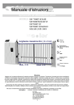
Viplax-I Transmitter (Handheld version)
Figure 1: ViplaxI Transmitter (handheld version).
Technical Description
The ViplaxI transmitter has two different case options. The a 3U unit is for 19" rackmount systems and the compact, high frequency resistant, metal case, is suited for high voltage applications. There are only a few adjustments, and three cables necessary to operate the transmitter unit. The following description is specifically for the handheld version, but the 3U 19" version operates the same way, except the power supply is connected via a backplane Basic or BasicBi.
The transmitter is a powerful unit, compact, easytoinstall and maintenance free thanks to the use of modern electronic components. It's main elements are; a high quality analog digital converter with high resolution, a modern Field Programmable Gate Array (FPGA), a highspeed bitstream converter and a highspeed optical transmitter unit. The data processing in the transmitter unit functions as follows: a BNC or SMBjack connects the analog input signal. One or the other is available for the handheld unit, both for the rack mount version. An input amplifier with 1MOhm input impedance has gain factors of 1.0; 2.0; 5.0 and 10.0. The selection of the desired gain factor is done via DIPswitches (Figure 2).
To avoid signal distortion through aliasing effects there is a 'Bessel' filter of 5th order (30dB/octave) between the preamplifier and the analog digital converter.
The AD converter has a resolution of 14bit and a sampling rate of 10 MSps transmitting analog signals with a bandwidth of 2.5MHz.
In addition to the AD payload there are four system check bits to transmit. The status of the power supply, the AD converter overflow bit, the comparator status and a freely usable FLAG „GP_BIT7“, which is connected to pin 9 of the auxiliary port.
Finally all parallel digital data are serialized, transmission check bits are generated and send through high speed optical link.
11
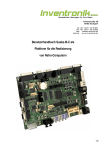
GAINSEL SW3
COMPSEL SW2
CMPLVL SW1
Jumper SJ8
Figure 2: Board Layout of the ViplaxI Transmitter (Handheld Version): DIPswitches for gain adjustments and the comperator.
Adjustment of the gain factor
Important notice: Do not try to remove the board from the right side of the case! This may damage either the case or the circuit board.
The only way to remove the circuit board from the handheld case is as shown in the figure below. Figure 3: Disassembly of the transmitter PCB to the left side!
The first step is to disassemble the circuit board from it's case. Remove the cap which covers the BNC/SMB jack and the ST jack on the left side of the fiber optic transmitter. Afterwards position the board as shown in figure 2 and you will find the gain DIP switches (GAIN_SEL SW3) in the upper left corner right above the BNC/SMB connector.
12
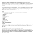
Figure 4: GAIN adjustment of the ViplaxI Transmitter via DIPswitches.
The adjustment of the gain factor is for the Viplax handheld transmitter revision C and for the Viplax handheld transmitter revision C10 slightly different. The version of the transmitter is labeled on the top of the printed circuit board as follows:
ViplaxTr V3RevC for the revision C type and
ViplaxTr V3RevC10 for the revision C10 type.
As the transmitter revision C provides four gain factors selectable via the switch 3 (GAINSEL), the transmitter revision C10 provides three gain factors and one attenuator selectable via GAINSEL.
The gain v is adjusted for the preamplifier by GAINSEL SW3 (see figure 4). Only one switch of the gain select switches must be turned on. Additionally, the attenuator switch may be turned on. In rows 4 and 5 of Table 1 the gain factors of the ViplaxI system (transmitterreceiver) are referenced to the analog outputs (BNC/SMB) of the receiver.
The output, connected to the BNC jack has a maximum amplitude of +/ 10V, and the SMB jack has an amplitude of +/ 10V. The different gain factors are adjustable as follows:
SW3:
1 On
2 On
3 On
4 – On Revision C
4 Revision C10:
Uinmax
±10.0V
±5.0V
±2.0V
±1V
on = : 1
off = :10
v
1.0
2.0
5.0
10.0
on = : 1
off = :10
Uin / UBNC
1.0
2.0
5.0
10.0
on = : 1
off = :10
Uin / USMB
1.0
2.0
5.0
10.0
on = : 1
off = :10
Table 1: Selectable gain factors and the resulting total gain v over the maximum input voltage for the transmitter revision C and revision C10.
13
The maximum input voltage must not exceed 10V for the transmitter revision C and revision C10 with no attenuation and not exceed 50V for the revision C10 with attenuation! The attenuation is 'on', when Switch 4 is off.
Adjustment of the Window Comparators of the Transmitter
The absolute value of the comparator threshold is configured through DIPswitches CMPLVL SW1 (see figures 2 and 5). The switch block is located above the FPGA (big square chip). Adjustment of the threshold is achieved in steps of 1%. Using the switches as 7bit binary, you need to encode the desired value. A switch in on position means a logic '1' and in off position a logic '0'. The switch labeled “1” is the least significant bit (LSB) and “7” is the most significant bit (MSB) of the 7 bit code. Important: Switch 8 of switch block SW1 is used to enable the comparator (On = enable). Factory setting is Off!
figure 5: COMPSEL SW2 and CMPLVL SW1 of the ViplaxI Transmitter.
Example: A threshold of 67% has a pattern of “On, Off, Off, Off, Off, On, On” (100011 = decimal 67).
Since there is a maximum of 127% adjustable, all values greater 100% are interpreted as 100%. The threshold value may be used for positive and negative comparator values. A threshold setting of 100% equals an A/D input signal of exactly 2.5V (absolute value). This means that the preamplified input signal must not exceed this value not to produce a A/D converter overflow or wrong comparator behaviour. With the switches COMPSEL SW2 there are negative, positive or both comparators selectable (see Table 2).
14
SW2 (2+1)
Description
On/On
Comparator detects overstepping of positive and negative thresholds.
On/Off
Comparator detects overstepping of positive thresholds only.
Off/On
Comparator detects overstepping of negative thresholds only.
Off/Off
not used
Table 2: Adjustment of the comparator functionality via SW2. Remark: All other switches of SW2 are not used
Transmitter comparators are helpful if you want to supervise the input signal directly at the transmitter case. Otherwise we recommend to use the more powerful receiver comparators. These comparators allow easy adjustment through PC integration. 15
Default Switch Settings:
The transmitter factory settings for the DIPswitches SW1SW3: Jumper:
Adjustment
Remarks
SW1 (71)
Off, On, On, Off, Off, On, Off
50,00%
SW2 (21)
On, On
both, positive and negative supervision
SW3 (41)
x1 (Off, Off, Off, On)
gain set to factor 1
SW1 (8)
Off
comparator inactive
Table 3: Factory settings of the DIPswitches.
Visualisation
Six LEDs are located on the top cover of ViplaxI transmitter (handheld version). All LEDs are used for status and error indication:
1. POWER: power status. This LED indicates the correct function of the internal charge pump. The charge pump is used to create the negative voltage supply. The LED may be darker than the other to avoid unnecessary load of the charge pump.
2. BATO.K.: voltage supervision control. You may use a battery to power the ViplaxI transmitter. This LED detects its correct charge condition. If the transmitter is operated by a power supply, the LED statically is turned on.
3. FAULT: collective error. It indicates either a comparator threshold or an AD converter overflow error.
4. ADFLT: overflow error of the AD converter. This LED indicates if the AD converter is driven into saturation by too high input signals. Solution is to reduce the input voltage or the amplification factor.
5. COMPFLT: comparator threshold event. The LED indicates the input voltage falls outside of the adjusted thresholds.
6. OPERATION: indicates steady operation, a well initialized transmitter without system faults or other errors (no comparator or AD converter errors and battery in good charge condition).
16
Auxiliary Port
The ViplaxI transmitter unit (handheld type) is equipped with a 10 pin auxiliary port header or optionally with a 5 pin Lemo 0B female plug. Both carries the 9V..12V operating voltage, GND and some user defined input/output lines. The signals are dedicated for system enhancements (please contact Inventronik GmbH for usage). The port connector Lemo 0B5. It is located right behind the right panel (Figure 2). Figure 6 shows the front view on the handheld case.
Figure 6: Lemo 5B2
Pin 1
Gnd
Pin 2
GPIO 1
Pin 3
GPIO 2
Pin 4
Vcc (9V..12V) or GPIO 3 (1)
Pin 5
Monitor (2)
table 4: Auxiliary port – Lemo header.
(2) GPIO3 is the output signal of the digital comparator. It can be accessed by connecting the jumper SJ8 to position 2. The VCC output on this pin is selected by connecting the jumper SJ8 to position 1. For detailed information see the printed circuit layout and the schematics in this document or contact nventronik GmbH.
(2) Is a mirror of the input signal equipped with an impedance converter with a max. output voltage of 2.5V (max. output current 20mA).
The pin header (10 pin) is also located right behind the right panel (Figure 2). The table 5 shows the pinout of this header.
Pin 1
GPIO 1
Pin 6
GPIO 5
Pin 2
GND
Pin 7
GPIO 6
Pin 3
GPIO 2
Pin 8
GPIO 7
Pin 4
GPIO 3(1)
Pin 9
GPIO 8
Pin 5
GPIO 4
Pin 10
VCCIO (3,3V)
table 5: Auxiliary port – 10 pin header.
(1) GPIO3 is the output signal of the digital comparator. For detailed information see the printed circuit layout and the schematics in this document or contact nventronik GmbH.
17
Power supply
The power supply with 9V...12V DC is used to power the ViplaxI transmitter (part of the delivery). The recommended setting is 9V. The connector type is Lemo 0B2. Figure 7 shows the front view.
Pin 1
Vcc (9V..12V)
Pin 2
Gnd
table 6: Power supply.
Figure 7: Lemo 0B2
The transmitter provides an optimized voltage control system to ease the use of a backup battery. Supervision of the battery charge condition is accomplished by a comparator. This status information is also available to the receiver unit. The delivered power supply is build in 50Hz technique. We do not recommend other power supplies such as switched mode power supplies. The usage of these modern supplies may reduce the analog signal quality dramatically!
The layout of the drills of the of the original power supply is given in Figure 8.
Figure 8: mechanical Layout of the stand alone transmitter power supply
18
Maintenance of the Transmitter
Under normal circumstances the ViplaxI transmitter requires no maintenance. Merely, if the supply voltage polarity has been connected in a wrong way, it is possible that the transmitters internal fuse got blown and must be replaced. The fuse is the F1 on the PCB (PicoFuse). See also the layouts in the attachment to this document.
If the transmitter is not connected to a fiber optic line, a cap should protect the optical subsystem to avoid any damage. Do not touch the fiber optic connector at its 'Ferrule'. If ViplaxI is not used, please cover the Ferrules with a dust caps.
19
Viplax-I Transmitter (Eurocard version)
The eCard version of the ViplaxI transmitter is a 3U unit for 19" rackmount systems. This version of the transmitter is basically the same as the handheld version. Therefore it is a good idea to read the specification of the handheld ViplaxI first. However there are differences which we will describe in this section of the handbook.
The Orientation of the Comparator DIP switches
The layout of the eCard transmitter is of course different to the handheld versions. Therefore the placement of the DIP switches for the comparator settings is different as the following figure illustrates.
Figure 9: Orientation of the comparator DIP switches
The used Power Supply
The power supply you want to use is from the same kind as the one for the ViplaxI receiver (see Power Supply for the Receiver). To interconnect the power supply and the ViplaxI eCard you will additionally need a backplane. Again you can use the same as we offer for the ViplaxI receiver (see Backplane Basic and BasicBi).
20
Additional I/O
Like ViplaxI handheld, there are additional I/Os available on the VG connector X5. These are dedicated for system enhancements (please contact Inventronik GmbH for usage).The table 7 below shows their usage.
connector Pinof X5
Function
X5A1
Monitor (1)
X5A17
Comp (Output fo the digital comparator)
X5A18
GPIO
X5A19
GPIO
X5A20
GPIO
X5A21
GPIO
X5A22
GPIO
X5A23
GPIO
X5A24
Thermo (2)
X5C3 – X5C15
Gnd
X5C18 – X5C30
Gnd
Table 7: Additional I/O
(1) Is a mirror of the input signal equipped with an impedance converter with a max. output voltage of 2.5V (max. output current 20mA).
(2) This signal is active high.
The Thermocontact 'Thermo' is a supervision of the temperature of the Viplax shunt, which is separately available as an accesoire. The contact is normally closed and therefore a low indicates no error. The input on the eCard is equipped with a pull up resistor. If there is another sensor than the shunt connected to the ViplaxI eCard transmitter, there must be taken care of shorting the 'Thermo' input and ground. The connector is illustrated in the following section. Thus pins 2 and 4 of this connector must be shorted or another appropriate sensor must be connected. Otherwise the eCard indicates a fault.
The 'Thermo' contact is combined with the fault signal LOW_BAT for there is never a LOW_BAT in the eCard and there is no 'Thermo' contact in the handheld. The error handling is therefore the same as for the LOW_BAT signal in the handheld version.
21
Analog Input or Sensor Plug
This connector is compared to ViplaxI handheld more flexible. Besides the analog input there is also a digital input signal and a supply voltage of +/15V. This makes it possible to connect additional special purpose sensors like the ViplaxI Shunt100A. The port connector is Lemo 0B5. It is located on the front panel of ViplaxI eCard. Figure 10 shows the front view of the female plug.
Figure 10: Lemo 5B2
Pin 1
Analog input
Pin 2
Digtal input (max. 15V)
Pin 3
+15V
Pin 4
Gnd
Pin 5
15V
table 8: Front panel female plug.
22
Viplax-I Receiver
Figure 11 : ViplaxI Receiver.
Technical Description
Digital data processing goes vice versa, compared to the transmitter. The received serial data stream will be converted into parallel equivalent. Transmission check bits indicate a valid reception. Next the system check bits and the userbit GP_BIT7 are extracted (see attachments: connector X6 pin number 8, (D_OUT1).
The remaining parallel data is converted back to an analog signal. Two output amplifiers provide the desired output signal conditioning. The analog output is available on two output connectors. Both outputs are capable to drive 50 Ohm loads (BNC jack and SM jack). The maximum output voltage swing is +/10V for the BNC jack and +/5V for the SM jack.
ViplaxI receivers are equipped with a microcontroller system board which provides the control and supervision of the digital data processing. Communication with a host computer is available through a USB or TCP/IP ethernet interface (depending on the type of the ViplaxI receiver).
The highspeed digital data processing is implemented in a field programmable gate aray (FPGA), which is a custom design.
Both, the microcontroller unit and the FPGA unit are separate modules pluggable to the ViplaxI system board. The microcontroller unit is either a MiniFlexUSB module (USB version) or a ARM7TDMI embedded Linux (TCP/IP version) from FSForth Systems. The FPGA is a Sphinx
C100RevA2 module. Further informations can be found in the chapters concerning the software configuration.
The receiver comes in euroboard form factor. All digital signals are connected to headers and/or 64 pin (a+c) VG type connector. The printed circuit board is installed in a 3U, 10HU plugin case.
23
Functional Description of the Error Logic
ViplaxI includes a fast error detection logic with a total response time of about 1,5µs (inclusive data transmission from the transmitter to the receiver). This system exists of two separate subsystems, the error processing system and the first fault memory.
Error Processing System
Transmitter and receiver errors will be collected and processed by this instance. The error processing system is optimized and needs only several system clock cycles (about 100ns). Compared to the total response time, the error handling is almost negligible.
The description of the error system behaviour and the resulting system status is described as follows. All signals are 'active high':
●
LOW_BAT: This error signal is caused by the transmitter. The signal is connected to the output D_OUT2 (connector X6, pin 7). It is also an input to the first fault memory.
●
COMP_FLT: This error signal is caused by the transmitter. The signal is connected to the output D_OUT3 (connector X6, pin 6). It is also an input to the first fault memory.
●
AD_FLT: This error signal is caused by the transmitter. The signal is connected to the output D_OUT4 (connector X6, pin 5). It is also an input to the first fault memory.
●
LINK_FLT: This signal indicates a fiber optic error. It is asserted in case of a not installed or faulty fiber optic cable. Other reasons are the damage of the optical subsystem in transmitter or receiver component. A LED on the front panel will indicate this error. Furthermore it is an input to the first fault memory and, in combination with the enable status of the microprocessor, connected as LINK_RDY to D_OUT5 (connector X6, pin4). ●
LINK_RDY: This status indicates the standby of the ViplaxI transmission system. LINK_RDY is deasserted if a LINK_FLT is asserted or if the microcontroller is in configuration process e.g. changing comparator thresholds to the FPGA. Right after power up or after a system reset, the signal is suppressed for about 300ms to guarantee the correct initialisation of the internal phase locked loop circuits. The signal is connected to the output D_OUT5 (connector X6, pin 4).
●
COMP_1L, COMP_1H, COMP_2L, COMP_2H: are the upper respective lower thresholds of the both receiver comparator units. These signals are not connected to any outputs but used as inputs to the first fault memory. If desired, the error detection system can be disabled. However this has also an effect to the first fault memory, since these errors are not available anymore. The only exception is the LINK_FLT signal which is always enabled to guarantee a reliable supervision of the fiber optic line.
Link Synchronisation
The Viplax system is with firmware 2.8 or up equipped with a link synchronisation state machine. This feature helps syncing the link during the startup sequence and works as follows:
If the Viplax system is turned on, the receiver detects the incoming data of the transmitter and 24
synchronizes it until a valid data connection is established. After the link is stable, the behaviour of the state machine depends on enabling the resynchronisation or not (EN_RESYNC). If it is on (enabled), the link synchronizes every time, the data gets invalid. If the EN_RESYNC is disabled, the synchronisation will never take place for a second time. In both cases, the link fault is unaffected of EN_RESYNC and is stored in the first fault memory in any case. It can be cleared by clearing the faults via the maintenance software or the dedicated pin on the backplane.
Figure 12 : ViplaxI Receiver (front view).
First Fault Memory
The First Fault Memory subsystem is responsible for storing errors. If an error occurs there might be a lot of consecutive errors as result of the initial fault. Since these consecutive errors are just a side effect the system masks them out. Only the first fault is stored.
There is one exception. The LINK_FLT error is stored in any case. In principle it is possible that more than one error is stored in the memory if they occur exactly at the same time. The first fault memory is available until erased by the user. Erasing the first fault memory is achieved by the service software (see below) or by asserting a TTL signal to the digital input D_IN6 (pin A25 of the 64 pin VG type connector X5). The service software allows erasing the first fault memory periodically.
The first fault memory generates the following error signals:
COMP_1L, COMP_1H, COMP_2L, COMP_2H, LOW_BAT, AD_FLT, COMP_FAULT and LINK_FLT.
The two last mentioned signals have a special function.
The COMP_FAULT is a collective error of the transmitter and receiver comparator thresholds.
A fault in the fiber optics occurs right after power up sequence or after a system reset. Responsible for this behaviour are the inrush effects of the built in phase locked loops. For this reason the LINK_FLT memory is disabled for about 300ms during power up or reset.
25
All memories except the LINK_FLT can be disabled or enabled via the service software. The memory locations are wired to the connector X5 (64 pin VG type connector) according to the following table.
26
Signal
connector pin of X5
LINK_FLT
A16
COMP_1L
A17
COMP_1H
A18
COMP_2L
A19
COMP_2H
A20
COMP_FAULT
A21
LOW_BAT
A22
AD_FLT
A23
Table 9: Error Signals wired to the connector X5.
Additionally the signals are wired to the 10 pin header X10 according to the following table: Signal
connector pin of X10
Signal
connector pin of X10
COMP1_L
PIN1
COMP1_H
PIN2
COMP2_L
PIN3
COMP2_H
PIN4
LINK_FLT
PIN5
LOW_BAT
PIN6
AD_FLT
PIN7
COMP_FAULT
PIN8
GND
PIN9
GND
PIN10
Table 10: Error Signals wired to the connector X10.
27
Signal LEDs
The ViplaxI receiver with USB has 7 LEDs (Figure 12). The LEDs are described as follows:
LINKFLT
There is trouble with the fiber optics.
STDBY
The ViplaxI transmission system is in standby and ready to operate.
ADFLT
The first fault was an AD_FLT .
LOWBAT
The first fault was a LOW_BAT.
COMPFLT
The first fault was a COMP_FLT .
USBTxD
USB send signal USBRxD
USB receive signal Table 11: Signalisation of the USB type.
The ViplaxI receiver with TCP/IP has 8 LEDs. The LEDs are described in the following table.
STDBY
The ViplaxI transmission system is in standby and ready to operate.
LINKFLT
There is trouble with the fiber optics.
ADFLT
The first fault was an AD_FLT .
LOWBAT
The first fault was a LOW_BAT.
COMPFLT
The first fault was a COMP_FLT .
ACTIVITY
There is data transfer activity in the ethernet.
STATUS 1
Not used so far.
STATUS 2
Not used so far.
Table 12: Signalisation of the TCP/IP type.
Digital Interface
The ViplaxI receiver does not only convert the received serial data stream into an analog output signal, it also provides a parallel TTL conform digital interface for the analog data at connector X5. This option allows to do real time data processing. The used 14bit data format is defines as:
A binary '0' („00000000000000“) represents 100% of the analog value, a „10000000000000“ represents 0% and a „11111111111111“ +100% of the analog value.
Additionally there is a control signal 'DA_D_VALID' , which indicates by its logic '1' state, that the data is valid. The signal 'DA_D_VALID' is asserted only in the case that no transmitter error is detected ('AD_FLT' or 'LOW_BAT') and the fiber optics work fine. As soon as a 'LINK_FLT' occurs, digital data is not valid indicated by 'DA_D_VALID' = 0. In this case the digital data itself will be set to „10000000000000“.
If the data processing system is disabled DA_D_VALID will be asserted even in the case, when there are transmitter errors detected ('AD_FLT', 'LOW_BAT'). The table below shows the connector 28
pinout for X5.
All signal are TTL compatible. The 14bit digital analog data is defined by DA_D13 downto DA_D0 where DA_D13 is the most significant bit and DA_D0 the least significant one.
Connector Pin
Signal
Connector Pin
Signal
X5A1
DA_D13
X5A9
DA_D5
X5A2
DA_D12
X5A10
DA_D4
X5A3
DA_D11
X5A11
DA_D3
X5A4
DA_D10
X5A12
DA_D2
X5A5
DA_D9
X5A13
DA_D1
X5A6
DA_D8
X5A14
DA_D0
X5A7
DA_D7
X5A15
DA_D_VALID
X5A8
DA_D6
Table 13: Digital Data wired to the connector X5.
Additionally the connector X11 is wired with the digital data and with the status information 'AD_FLT' of the first fault memory. Table 14 shows the connector layout.
Connector Pin
Signal
Connector Pin
Signal
X11PIN3
DA_D13
X11PIN11
DA_D5
X11PIN4
DA_D12
X11PIN12
DA_D4
X11PIN5
DA_D11
X11PIN13
DA_D3
X11PIN6
DA_D10
X11PIN14
DA_D2
X11PIN7
DA_D9
X11PIN15
DA_D1
X11PIN8
DA_D8
X11PIN16
DA_D0
X11PIN9
DA_D7
X11PIN17
DA_D_VALID
X11PIN10
DA_D6
X11PIN18
AD_FLT
Table 14: Digital Interface wired to connector X11.
Digital I/OPorts
In the preceding chapters, most of the digital signals are explained. Mentioned but not described up to now is the RESETn which is wired to D_OUT6 respective to the connector X6 pin number 3. The signal is also connected to the reset push button, which is located behind the small hole of the front panel and is low active. D_OUT6 can be used to initialize peripheral components together with the ViplaxI transmission system.
A collection of all connector layouts can be found in the appendix of this document.
29
Power Supply for the Receiver
The receiver requires three different voltages. Two times 15 VAC / 250mA and 9VAC / 1.4A. Inventronik GmbH has a suitable power supply in its portfolio.
The supply for the receiver can be connected to the 64 pin VG type connector or to clamps located behind the VG connector. Last mentioned are to the best advantage if the receiver shall not be mounted in a 19“ rack, but used as a stand alone component. In this case the rear panel of the plug
in unit has to be removed to gain access to the clamps. The layout of the receiver (see appendix) or Figure 11 shows the position of the clamps in detail. The connector X5 connects to the power supplies as follows:
Connector Pin
Signal
X5C1
15V AC I
X5C2
15V AC I
X5C16
9V AC
X5C17
9V AC
X5C31
15V AC II
X5C32
15V AC II
Table 15: Supply voltages for the receiver connected via connector X5.
Power Up Sequence
The power up sequence of the ViplaxI transmission system is not critical. It doesn't matter in which order the transmitter and the receiver are powered on. Merely there is the effect, that the LINK_FLT is suppressed for 300ms due to the phase locked loops as mentioned above. Is the link after 300ms not established, the LINK_FLT can not be cleared. After clearing the faults by a reset or by the service software, the ViplaxI transmission system is ready to use.
30
Maintenance of the Receiver
The ViplaxI receiver is completely maintenance free. Take care of the very sensitive fiber optics.
If the receiver is not connected to a fiber optic line, a cap should protect the optical subsystem to avoid any damage. Do not touch the fiber optic connector at its 'Ferrule'. If ViplaxI is not used, please cover the Ferrules with dust caps.
Maintenance of the Transmission System
The ViplaxI transmission system is nearly free of maintenance except of long term offset re
calibrations. Ageing of components over the time may make this necessary. The user can independently calibrate the offset values of transmitter A/D converter and the receiver D/A converter via the system software.
Offset Calibration
Prerequisites for the calibration of the ViplaxI transmission system is a high quality multimeter and a 50Ω BNCterminator for the BNC type transmitter or a suitable SMB terminator with 50Ω (a SMBshort circuit connector will do it too). The calibration should be accomplished on equipment with operating temperature. An operation of one hour before starting the calibration process is recommended.
First step is connecting the multimeter (DC voltage measurement) to the receivers BNC jack. The receiver calibration is done with disconnected fiber optic, i. e. with asserted LINK_FLT. To adjust the offset of the receiver it is necessary to start the service program. The offset calibration is very simple. The measured offset has to be minimized with the software receiver calibration buttons.
In a next step, a terminator must be installed at the transmitter and the fiber optic link has to be established. The LINK_FLT needs to be cleared by the service software. Now the ViplaxI transmission system should be in operation condition. To minimize the offset use again the software calibration buttons, but this time for the transmitter.
ViplaxI is adjustable to a minimum offset of about 1mV. An optimal 0.0mV offset is not possible due to noise, the relative simple offset calibration equipment and also due to the finite quantisation of the AD and DA converters.
31
Viplax-I Service-Software
ViplaxI Interface Options
There are two options to establish communication between PC and the ViplaxI receiver. The USB interface is useful if the ViplaxI receiver is nearby or if you have a notebook at your disposal. For long distance configuration we recommend the TCP/IP ethernet option. LANs are widely used and the necessary infrastructure normally allows for remote control of the ViplaxI receiver. The following sections will explain how to install the necessary device drivers and how to use the software.
USB Option: Installing a Driver for a Virtual USB/RS232 Port
The MiniFlexUSB needs to be connected with a power supply and the USB cable, after which you will be asked to select first a USB<>Serial driver and finally the USBSerialPort driver. You'll find these drivers on the productCD in the directory Windows\USB Driver. Why is this driver needed? The driver maps the USB interface on your PC to a virtual serial RS232C interface. Programming a RS232C interface is much easier than programming the USB interface because you don't have to know about complicated USB protocols and you can use many welltested programming libraries with serial communication support. Exchanging data via USB is really easy this way.
Please note: the driver version on the product is not certified by Windows XP (a warning appears). 32
Screenshots of the Installation Process
After connecting the MiniFlexUSB to your PC, a dialog window opens (see figure 4).
Don't use automatic installation here. Please use the second option in the dialog window to allow selection of the appropriate directory. Press
WEITER to continue. Figure 13: Windows hardware facility assistant
The following dialog appears:
Please choose the location of the driver. You will find it on the productCD in the folder (Windows\USB Driver). The installation procedure ends with the last dialog window. This will be the the „USB Serial Port“ installation. After that the virtual serial COM is ready for use.
Figure 14: Selection of the driver directory
PCs are normally equipped with multiple COMports so the virtual COMport is not mapped to a specific port number (e.g. COM3). Windows has its own scheme for the distribution of virtual port numbers. How to find the right COM port is discussed later in this documentation.
33
Figure 15: Finish the driver installation; Serial converter
Figure 16: Finish the driver installation; USB serial port driver
34
Verifying the COMPorts
Next you should find out which COMport is used for the virtual serial interface. The COMport in use depends on the number of COMports already available in your PC. To figure it out you'll have to open the device manager (system/hardware) and open connectors (COM and LPT). The USB Serial Port shows up (here COM4 is used for the USB Serial Port).
Figure 17: USB Serial Port (COMx)
ViplaxI Configuration Program
For the Windows 2000/XP™ operating system we offer an easy to use configuration program. All adjustments are spread over a tabbed form. The following screenshot shows what can be done.
1. PROPERTIES Choose a serial port: In this dialog form choose the virtual serial interface which you previously found to correspond with the used USBport. Changes to the ViplaxI settings will not be transferred to the ViplaxI system until you click to the |SEND CONFIGURATION TO VIPLAXONFIGURATION| button.
Figure 18: ViplaxI configuration program, serial interface
35
2. COMPARATORES Adjustments to the threshold comparators:
Input values are percentage values. Since we have a bipolar voltage input we extended the range and allow 100% to 100% values. Values in the range from 0% to 100% define a positive input threshold, 100% to 0% a negative one. The threshold comparator triggers an error if the input voltage falls below or raises above the adjusted thresholds.
Figure 19: ViplaxI configuration program, thresholds
3. Comperators Adjustments for the 2nd threshold comparator: (see above)
4. ERROR HANDLING:
The first checkbox enables or disables the general error handling. The second one activates the firstfault
memory option. If you want to erase upcoming errors in certain time cycles, you might use the cyclic error erase function REMOVE ERRORS EVERY X SEC '' disables the cyclic error erase function.
The red error erase button REMOVE ERRORS erases an error once.
Figure 20: ViplaxI configuration program, error handling
36
5. OFFSET ADJUSTMENTS:
The offset adjustment can be done separately for the ViplaxI sender and receiver. Each offset setting can take values between 127 and 128. To change an offset value you have to enable the settings and use the up and down arrows. Normally it only takes small values to accomplish a satisfying offset calibration. Please note: Using the SEND CONFIGURATION TO VIPLAX button is not necessary for the offset calibration! (See also Offset Calibration)
Figure 21:ViplaxI configuration program, offset adjustments
SEND CONFIGURATION TO VIPLAX
This button sends all adjustments to the ViplaxI receiver. If there is a problem with the serial port or if ViplaxI doesn't answer correctly you will get an error message. If you need to integrate these ViplaxI functions into your own program, please let us know. We can provide information about the used protocol. All commands are in simple ASCII form. 37
TCP/IP EthernetInterface: Using a WebBrowser for ViplaxI Configuration
Overview
A web server on the embedded Linux system in the ViplaxI receiver allows you to use a browser to adjust the various settings of ViplaxI. CGIscripts provide basic authentication and allow easy configuration of the whole system.
Getting started
Before you poweron ViplaxI, you must establish a connection to your local network. A DHCP server is mandatory for the first startup. This guarantees that ViplaxI can retrieve a valid IP address. Next you will need to know the assigned IP address to be able to make adjustments to your configuration with a web browser. Resolving the IP address can be solved in different ways. One possibility is to log the boot process with a serial RS232C monitor program on Viplaxs RS232C port. Use the NullModemCable (part of the ViplaxI shipping) to connect your PC with the ViplaxI serial port. Now, you have to start a monitor program. For Win32/XP you could use HYPERTERM which is part of Windows™. If you use Linux/Unix you might find MINICOM or SEYON helpful to monitor the boot messages. Please read also the man pages to those programs.
The serial port settings are as follows:
●
Baudrate: 38400
●
Databits: 8
●
Stopbits: 1
●
Parity: none
After a reset or after connecting ViplaxI to the power supply, you will get the following messages in your terminal program:
LxNETES Bootloader $Revision: 1.19 $
ABCDEFGHINO@00001618
Bootstrap: 03ff
...
after awhile the boot process stops and you will see a command line input prompt '#' (hash).
#
38
Now, if you scroll up the hyperterm output a bit, you will see following lines:
Sending DHCP requests ., OK
IPConfig: Got DHCP answer from DHCPSERVERADDRESS, my address is ViplaxIPADDRESS
ViplaxIPADDRESS is the IP address you will need to access the web frontend. Now open your favourite web browser and enter as URI: http://ViplaxIPADDRESS.
In our case we would type http://192.168.1.53
If you have administrator privileges on the DHCP server, you could look in the DHCPlogfiles to figure out the assigned IP address, or if you are connected to a small local area network you might use NMAP to scan your network for new network devices. If nmap detects a device from FSForth it might be ViplaxI!
ViplaxI Start Page
Please use your favourite web
browser and follow the link HERE to be forwarded to the authentication page.
Figure 22:WelcomeScreen
39
ViplaxI Login (HTTPAuthentication)
All ViplaxI functions are protected through authentication. You must login to be able to make any changes. To login successfully your browser cookies must be turned on! Firsttime login is „admin“ and „1234“ is the default password. It is a good idea to change the password immediately after you have successfully loggedin.
If you can't login please confirm that your browser is accepting cookies.
Figure 23: User Authentication
ViplaxI Specific Adjustments
This figure shows all possible ViplaxI adjustments, which we have explained in detail in earlier sections of this manual. Figure 24: ViplaxI Adjustments
40
●
Adjusting the thresholds (see also Comparatores
Adjustments to the threshold
comparators)
●
Error handling (see also Error
Handling)
●
Erase current errors.
●
Offset adjustment (see also Offset Calibration)
Change Password
Not much to explain on this page! Anyhow, for security reasons it is necessary to type in your old password, then your new one and repeat.
In case you have forgotten your password, please email us and we will provide instructions on how to reset the password.
Figure 25:Change password
41
Network Settings
Network integration with ViplaxI is easy. All adjustments can be made using the settings you see in the above screenshot. Predefined is the usage of a DHCP server. As mentioned earlier, to get things going, you need to have DHCP on the first time you boot your new ViplaxI. We recommend using a fixed IP address afterwards to avoid the Worst Case Scenerio or waiting for an unresponsive DHCP server (disconnected cable, unreachable DHCP server etc.)
Worst Case Scenerio: the DHCP server never answers and ViplaxI stays in an endlessloop stubbornly refusing start any services. Using a fixed IP avoids this!
Figure 26: ViplaxI Network settings
The settings Gateway and DNS are not currently in use.
The telnet server enables remote sessions via TCP/IP. Once connected through a telnet client the user can reset some settings (e.g. passwords etc.). If you wish to use telnet please contact Inventronik GmbH. Do not use this option if you do not intend to access the system via telnet! Please note: telnet sessions do not have authentication!
After changing any of the above settings, you must reboot the ViplaxI Linux system.
42
TCP/IP Protocol SNMP (Simple Network Management Protocol)
SNMP is widely used in a TCP/IP network, mostly for controlling of communication equipment. Since ViplaxI can be considered as a network device, we offer a SNMP interface to control Viplax
I.
Despite the fact that SNMP says it is a simple protocol, it is not easy to understand. We highly recommend that you checkout our link section for further readings.
Presumptions
SNMP applications are build as typical client/server applications. The client, also called Manager, is located on the controlling PC. The server, also called Agent, is ready to use on the ViplaxI
Receiver.
To be able to instantiate a communication path between manager and agent, you will need some basic programs on the controlling PC. In our case we used the open source NETSNMP (see http://netsnmp.org). The ViplaxI SNMP
agent uses the same software in version 5.2.1.
ViplaxI uses SNMPProtocol V2 (but V3 should work too, but we did not test this). Installation (for Linux/Unix)
NETSNMP is easy to install. Just use the classic "./configure make make install" commands to execute configuration, compiling and installing of the software package. Anyhow, if you don't want to use Linux/Unix, there are also ports for Win32 or MacOSX, but we did not try that. After installing the software you are in need of an additional MIBfile (Management Information Base), that defines the ViplaxI agent functions. This VIPLAXMIB ca be obtained from the ViplaxI WebHomepage (http://viplaxipaddress). Before you are able to play with SNMP you have to copy this file (VIPLAXMIB.txt) to the MIB directory onto your PC. If you have chosen a standard installation of NETSNMP you have to use the directory /usr/local/share/snmp/mibs. This directory contains all known SNMPMIBs from NETSNMP.
SNMP at a glance For the first test we do not need ViplaxI yet. Instead we will scan the structure of the previously installed ViplaxMIB. Please use the shell command: snmptranslate Tp IR m ALL inventronik
and you should see something like: 43
+inventronik(22237) | +viplaxSnmpMIB(1) | +vsMIBComparators(1) | | | + RW Integer32 upperThresholdComp1(1) | | Range: 100..100 | + RW Integer32 lowerThresholdComp1(2) | | Range: 100..100 | + RW Integer32 upperThresholdComp2(3) | | Range: 100..100 | + RW Integer32 lowerThresholdComp2(4) | Range: 100..100 | +vsMIBErrorHandling(2) | | | + RW EnumVal enableErrorHandling(1) | | Values: enabled(1), disabled(2) | + RW EnumVal activateErrorStorage(2) | | Values: enabled(1), disabled(2) | + RW Integer32 eraseErrorsPeriodically(3) | | Range: 1..90 | + RW Integer32 eraseErrorsOnce(4) | Range: 1 | +vsMIBErrorCounters(3) | + RW Integer32 totalErrorsUpperComp1(1) + RW Integer32 totalErrorsLowerComp1(2) + RW Integer32 totalErrorsUpperComp2(3) + RW Integer32 totalErrorsLowerComp2(4) The branches vsMIBComparators and vsMIBErrorHandling carry the basic ViplaxI parameters. We will show you how to read and write these parameters later. New, and exclusive to SNMP are 4 parameters in the branch vsMIBErrorCounters. These registers count for each threshold separately the oversteps. You can reset the registers anytime you want. After a new start of ViplaxI these registers have a zero value.
44
Read ViplaxI parameters If you want to read back a ViplaxI parameter you will need the following command:
snmpget m ALL c viplaxro v 2c <ipaddr> VIPLAXMIB::<Regname>.0 The readonly password is "viplaxro", <ipaddr> is the IP address of the agent (ViplaxI) and <Regnamme> is the name of a leaf from ViplaxI MIBstructure, for example upperThresholdComp1. The trailing ".0" says that the value is a scalar type. If you want to read all ViplaxI parameters at once, than you execute a snmpwalk command, here for example: snmpwalk m ALL c viplaxro v 2c 192.168.1.52 inventronik
Change ViplaxI parameters This is as easy as reading a ViplaxI parameter. The following command will write a new value into the ViplaxI register. snmpset m ALL c vplx9u1o1 v 2c <ipaddr> VIPLAXMIB::<Regname>.0 i <Value>
"vplx9u1o1" is the readwrite password.
Unfortunately this password can't be changed; it is part of the ROM configuration. Later on we will support SNMP.V3 which will encrypt the password before it is sent over the network. After that we will add support for changeable password storage. The command parameter "i" in the above command says that the value is an integer (Float values are not explicitly supported by SNMP). <Value> is the integer value of the ViplaxI parameter. One important remark regarding eraseErrorsOnce: If you want to delete an error, you must write a zero value into the register. Reading a value different than zero means there has been an error triggered.
What's Next (To do): We plan to extent the SNMP functionality and we will add trap support. Which traps we will covered has to be defined. Possibilities are: 45
●
Authentication Trap: Wrong SNMP or HTTP password entered. ●
Error Trap: As soon as an error has been triggered (probably in different classes). ●
Suggestions are welcome! Links: 46
●
http://www.netsnmp.org
– a lot about SNMP ●
http://www.netsnmp.org/tutorial/tutorial5/toolkit/mfd/
MIB for Dummies ●
http://www.enseirb.fr/~kadionik/embedded/snmp/english/netsnmp_english.html SNMP for embedded Applications (very clear and easy to understand) Changing the FPGAConfigware
Under normal circumstances it is not necessary to change the FPGA content of the ViplaxI receiver or sender. However, for exceptions to the rule, it might come in handy if there are minor changes. The receiver contains the FPGA module 'SphinxC100Rev.A' also produced by Inventronik GmbH. On our website, we provide a detailed documentation that explains the necessary steps to configure the FPGA. Programming must take place over the 'Active Serial' connector. The JTAG interface is not used.
The transmitter does not contain a 'SphinxC100Rev.A' module, but the programming remains the same. The unused JTAG interface has been removed.
Changing the Microcontroller Firmware (MiniFlex only)
Again, under normal circumstances there is no need to change the firmware. In the interests of software flexibility there is a possibility to make adjustments to the firmware to meet special requirements in industrial and scientific applications. Please contact us with your specifications.
The USB version of the ViplaxI receiver uses the 'MiniFlexUSB' developed by Inventronik GmbH. The documentation in the download area of our website explains how to program the controller. Software Support
Inventronik GmbH offers development services to extend or expand the functionality of ViplaxI. Please contact us if you have further questions.
47
Appendix
Technical Data
Transmitter_V3_RevA, Receiver_V3_RevA:
Input Amplifier:
Input voltage range: 0.25V; V; V; V; V.
Voltage Gain: 32dB; 20dB; 12dB; 8dB; 0dB (adjustable).
AntiAliasingFilter:
Bessel Low Pass Filter 4th Order: 3dB Frequency: 2.5MHz
Voltage Drop near the 3dB Frequency: 20dB/Octave.
Remark: The theoretical voltage drop of 24dB is not reached due to the not ideal but nevertheless accurate behavior of the installed operational amplifiers.
A/DWandler:
Resolution:
Samplingrate: Signal to Noise Ratio:
Integral Linearity Error:
Differential Nonlinearity:
14 bit.
10Mbps.
>65 dB.
LSB.
LSB.
Further information: see the Analog Devices AD9240 data sheet.
Digitale Signal Processing:
Signal Latency:
System Bandwidth:
Window Comparators:
System Status Bits:
Digital Inputs:
Digital Outputs:
Output voltage levels:
Current: Input voltage levels:
Visualisation:
Fiber Optics:
Maximum Bit Stream Frequency: Optical Wave Lenght
Fiber Type:
Connector:
Maximum Length:
48
< 2.5µs
2.5MHz
bipolar, adjustable.
A/DOverflow; Battery Load Condition, System Error,
Comparator Thresholds.
5 Pin (Transmitter), 7 Pin (Receiver).
5 Pin (Transmitter), 7 Pin (Receiver).
5V at the VG type connector, 3.3V at the pin headers. 10mA.
TTL tolerant.
All relevant System Status Bits via LEDs.
200 Mbit.
1300nm.
50µm oder 62.5µm core, multimode.
ST Type.
1000m. (the maximum achievable length is dependant on the quality and condition of the fiber optic cable.)
User definable Gains:
D/A converter:
Resolution:
Sampling Rate: Spurious Free Dynamic Range:
Integral Linearity Error:
Differential Nonlinearity:
1.176 (Stellung SJ3: 23; Stellung SJ4: x1.176; Uinmax =2.126V)
0.294 (Stellung SJ3: 12; Stellung SJ4: x1.176; Uinmax =8.503V)
14 bit.
125Mbps.
>75dB.
LSB.
LSB (typ).
Further information: see the Analog Devices AD9764 data sheet.
Output Amplifier (Twin Amplifier):
Output Voltage Range:
V (BNC), V (SMB), (full conduction).
Output Impedance:
50 Ohm.
Voltage Supply:
Transmitter:
Receiver: 12 VAC / 1.2A.
15VAC / 0.25A; 15 VAC / 0.25A; 9VAC / 1.4A.
As mentioned above: we do not recommend the use of switched mode power supplies!
49
Connector Pinouts
Signal
Connector Pin
Signal
Connector Pin
GND
PIN1
GND
PIN2
RA5 (not used)
PIN3
RA0 (not used)
PIN4
RA4 (not used)
PIN5
RA1 (not used)
PIN6
RA3 (not used)
PIN7
RA2 (not used)
PIN8
+5V
PIN9
+5V
PIN10
Table 16: Connector SV1; Receiver.
Signal
Connector Pin
Signal
Connector Pin
GND
PIN1
GND
PIN2
RC5 (not used)
PIN3
RC0 (not used)
PIN4
STDP (not used)
PIN5
RC1 (not used)
PIN6
not connected
PIN7
RC2 (not used)
PIN8
+5V
PIN9
+5V
PIN10
Table 17: Connector SV2; Receiver.
50
Connector Pin
Signal
Connector Pin
Signal
X5A1
DA_D13
X5C1
15V AC I
X5A2
DA_D12
X5C2
15V AC I
X5A3
DA_D11
X5C3
GND
X5A4
DA_D10
X5C4
GND
X5A5
DA_D9
X5C5
GND
X5A6
DA_D8
X5C6
GND
X5A7
DA_D7
X5C7
GND
X5A8
DA_D6
X5C8
GND
X5A9
DA_D5
X5C9
GND
X5A10
DA_D4
X5C10
GND
X5A11
DA_D3
X5C11
GND
X5A12
DA_D2
X5C12
GND
X5A13
DA_D1
X5C13
GND
X5A14
DA_D0
X5C14
GND
X5A15
DA_D_VALID (Memory)
X5C15
GND
X5A16
LINK_FLT (Memory)
X5C16
9V AC
X5A17
COMP_1L (Memory)
X5C17
9V AC
X5A18
COMP_1H (Memory)
X5C18
GND
X5A19
COMP_2L (Memory)
X5C19
GND
X5A20
COMP_2H (Memory)
X5C20
GND
X5A21
COMP_FAULT (Memory)
X5C21
GND
X5A22
LOW_BAT (Memory)
X5C22
GND
X5A23
AD_FLT
X5C23
GND
X5A24
D_OUT6 (RESETn)
X5C24
GND
X5A25
D_IN6 (clear fault memory)
X5C25
GND
X5A26
D_IN5 (not used)
X5C26
GND
X5A27
D_IN4 (not used)
X5C27
GND
X5A28
D_IN3 (not used)
X5C28
GND
X5A29
D_IN2 (not used)
X5C29
GND
X5A30
D_IN1 (not used)
X5C30
GND
X5A31
FLAG1 (not used)
X5C31
15V AC II
X5A32
FLAG2 (not used)
X5C32
15V AC II
Table 18: Connector X5; Receiver.
51
Signal
Connector Pin
Signal
Connector Pin
+5V
PIN1
+5V
PIN2
D_OUT6 (RESETn)
PIN3
D_OUT5 (LINK_RDY)
PIN4
D_OUT4 (AD_FLT)
PIN5
D_OUT3 (COMP_FLT)
PIN6
D_OUT2 (LOW_BAT)
PIN7
D_OUT1 (GB_BIT7)
PIN8
GND
PIN9
GND
PIN10
Table 19: Connector X6; Receiver.
Signal
Connector Pin
Signal
Connector Pin
+5V
PIN1
+5V
PIN2
D_IN6 (not used) PIN3
D_IN5 (not used)
PIN4
D_IN4 (not used)
PIN5
D_IN3 (not used)
PIN6
D_IN2 (not used)
PIN7
D_IN1 (not used)
PIN8
GND
PIN9
GND
PIN10
Table 20: Connector X7; Receiver.
52
Signal
Connector Pin
Signal
Connector Pin
COMP1_L
PIN1
COMP1_H
PIN2
COMP2_L
PIN3
COMP2_H
PIN4
LINK_FLT
PIN5
LOW_BAT
PIN6
AD_FLT
PIN7
COMP_FAULT
PIN8
GND
PIN9
GND
PIN10
Table 21: Connector X10; Receiver.
Connector Pin
Signal
Connector Pin
Signal
X11PIN1
+5V
X11PIN11
DA_D5
X11PIN2
+5V
X11PIN12
DA_D4
X11PIN3
DA_D13
X11PIN13
DA_D3
X11PIN4
DA_D12
X11PIN14
DA_D2
X11PIN5
DA_D11
X11PIN15
DA_D1
X11PIN6
DA_D10
X11PIN16
DA_D0
X11PIN7
DA_D9
X11PIN17
DA_D_VALID
X11PIN8
DA_D8
X11PIN18
AD_FLT
X11PIN9
DA_D7
X11PIN19
GND
X11PIN10
DA_D6
X11PIN20
GND
Table 22: Connector X11; Receiver.
Signal
Connector Pin
Signal
Connector Pin
I/O (not used)
PIN1
GND
PIN2
I/O (not used)
PIN3
I/O (not used)
PIN4
I/O (not used)
PIN5
I/O (not used)
PIN6
I/O (not used)
PIN7
I/O (not used)
PIN8
I/O (not used)
PIN9
3,3V
PIN10
Table 23: Connector SV2; Transmitter.
53
Test Procedure for Transmitter and Receiver
To guarantee a high product quality for every ViplaxI transmitter/receiver we've tested them thoroughly. An additional burnin phase should avoid early failures. The test procedure is written down in a test protocol and is accomplished in three steps: the transmitter, the receiver and the systemtest (operating one transmitter in connection with one receiver).
Remark: ViplaxI Version III were sold and tested in pairs to increase accuracy. However Inventronik GmbH was able to increase overall accuracy of the ViplaxI line. Due to this we've abandoned pairwise testing. Transmitter Functional Tests:
●
Basic functions (JTAG programming, voltage tests)
●
Comparator functionality
●
Error system
●
Visualisation
●
Amplifier functionality
Receiver Functional Tests:
●
Basic functions (JTAG programming, voltage tests)
●
Comparator functionality
●
Error system
●
Visualisation
●
Test of the output amplifier
●
Test of the USB/Ethernet configuration interface
●
Test of the RS232 interface (if available)
●
Digital inputs and digital outputs.
During the tests the absolute accuracy of the gain is adjusted, and the components are operated over 48 hours (burnin test).
54
Printed circuit diagrams
All our customers who bought ViplaxI components, are able to request schematics of the purchased ViplaxI components.
55
Accessories
Receiver Power Supply
The ViplaxI receiver requires three supply voltages. 9VAC and two times 15VAC. Inventronik GmbH delivers a power supply which is designed for this purpose (Figure 28). The power supply delivers 9V with a current of 2,78A and 15V with each 0,83A. The power is sufficient to operate two ViplaxI receivers with one power supply. The supply is designed for mains of 230V. Other versions are available on request. The form factor is provided for installation in 19” subracks. The sizes are 3U and 14HU.
Figure 27:
Figure 28:
Figure 27 shows the rear panel of the power supply. The connector is a DIN41612 version H15. The pinout is shown in the following table:
Signal
Connector Pin
Signal
Connector Pin
9VAC_1
Z4 and D6
N
Z28
9VAC_2
Z8 and D10
L
D30
15VACI_1
Z16
PE
Z32
15VACI_2
D18
15VACII_1
Z20
no used
Z12, Z24, D14
15VACII_2
D22
no Pin
D26
Table 24: Pinout of the power supply connector.
The 9V supply voltage has two pins for each pole. The first 15V voltage source is connected to Z16 and D18 and the second one to Z20 and D22.
The mains (230VAC) are connected to the pins Z28 (Null), D30 (Phase) and Z32 (Protection Earth). Due to safety reasons, the pin D26 is removed. Attention: the pins Z28 and D30 may not be interchanged!
56
On the front panel of the power supply are four LEDs. Three (green) indicate the correct operation of the three voltages ('15VACII', '15VACI' und '9VAC') and the fourth one (red) is used for the supervision of the fuse. In normal operation the green LEDs are 'on' and the red one is 'off'. If the fuse is blown, the red LED is 'on'. Hint: If the power supplies are connected to a weak load, the red LED may shine a little bit even if the fuse is ok. This is due to leakage current of the fuse fault circuit and does not indicate a malfunction of the power supply.
A defective fuse must be exchanged with the correct value of 2AT. The fuse form factor is (4x20mm), glass tube type.
57
Backplane Basic and BasicBi
Figure 29: Front und Rearview of the Backplane BasicBi
Wiring one or two ViplaxI receivers with one receiver power supply, Inventronik GmbH offers two different backplanes. They are designed for the use in 19” subracks. The version Backplane Basic connects one ViplaxI receiver with a power supply and the Backplane BasicBi is built to assemble two receivers to one power supply.
The backplanes are mounted directly to 19” subracks with small auxiliary parts (distances of 3mm) but without “ZSchienen”. This construction supports isolation of the mains potential from the normally to earth ground connected subrack. To ease the installation, the backplane is marked on the front side with TOP. Mounted, the ViplaxI receivers are located to the left of the power supply.
X8
X6
X9
X10
X4
Figure 30: Backplane BasicBi rear view
58
X5
X7
On the rear side there are four terminals for the Backplane Basic and 7 terminals for the BasicBi. The small one (X4) is wired to the mains. The pinout is shown in Figure 30.
Important: The pinout of the mains connector has to be done as follows: ●
L = Phase
●
PE = Protection Earth
●
N = Null. Interchanging this pinout is not only dangerous, it can destroy the ViplaxI receivers or the power supply.
The terminals X5 to X10 carry the digital inputs and outputs of the ViplaxI receivers. The pinouts of these terminals are shown in the printed circuit diagram for the Backplane BasicBi on the next page. For the Backplane Basic the terminals X1, X5, X6 and X7 are missing. The orientation of the connectors are shown in the printed circuit board as top and bottom. This is equivalent to the orientation in Figure 29. In the following table there is a summary of all connector pinouts (X5 / X8; X6 / X9; X7 / X10).
Pin X6/8
Signal
Pin X7/9
Signal
Pin X8/10
Signal
1 (top)
A1
1 (top)
A13
1 (top)
A25
2
A2
2
A14
2
A26
3
A3
3
A15
3
A27
4
A4
4
A16
4
A28
5
A5
5
A17
5
A29
6
A6
6
A18
6
A30
7
A7
7
A19
7
A31
8
A8
8
A20
8
A32
9
A9
9
A21
9
GND
10
A10
10
A22
10
GND
11
A11
11
A23
11
GND
12 (bottom)
A12
12 (bottom)
A24
12 (bottom)
GND
Table 25: Pinout of the Terminals X5 to X10 of the Backplane.
59
60
Repair
In case of a faulty component, please send the device along with an exact description of the error directly to Inventronik GmbH.
61