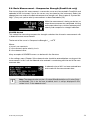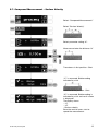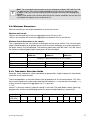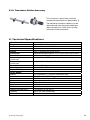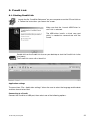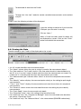
1
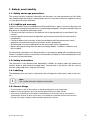
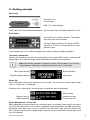
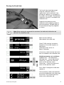
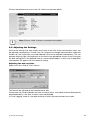
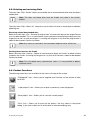
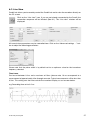
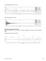
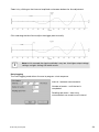
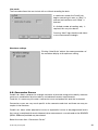
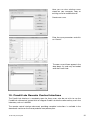
Operating Instructions
Pundit Lab / Pundit Lab+
Ultrasonic Instrument
Made in Switzerland
Made in Switzerland
... more than 50 years of know-how you can measure!
Table of Contents
1.
Safety and Liability 3
2.
Getting started 4
3.
System Settings 6
4.
Viewing the Waveform 8
5.
Measuring with Pundit Lab
9
5.1.
Preparation 9
5.2.
Basic Measurements10
5.3.
Basic Measurement – Pulse Velocity
11
5.4.
Basic Measurement – Waveform Display
12
5.5.
Basic Measurement – Path Length
13
5.6.
Basic Measurement – Compressive Strength (Pundit Lab+ only)
14
5.7.
Compound Measurement – Surface Velocity
15
5.8.
Compound Measurement – Perpendicular Crack Depth
16
5.9.
Minimum Dimensions17
5.10.
Transducer Selection Guide17
5.11.
250 kHz Shear Wave Transducers
18
5.12.
Transducer Holder Accessory19
6.
Technical Specifications19
7.
Part Numbers and Accessories20
7.1.
Units20
7.2.
Transducers20
7.3.
Parts and Accessories20
8.
Maintenance and Support21
9.
Pundit Link22
9.1.
Starting Pundit Lin22
9.2.
Viewing the Data23
9.3.
Adjusting the Settings24
9.4.
Exporting Data25
9.5.
Deleting and restoring Data26
9.6.
Further Functions26
9.7.
Live View27
9.8.
Conversion Curves30
10.
Pundit Lab Remote Control Interface
31
Standards and Guidelines
Pundit Lab complies with the following standards: EN 12504-4 (Europe), ASTM C597-02 (North
America), BS 1881 Part 203 (UK), ISO1920-7:2004 (International), IS13311 (India), CECS21 (China)
© 2014 by Proceq SA 2
1. Safety and Liability
1.1. Safety and usage precautions
This manual contains important information on the safety, use and maintenance of the Pundit
Lab. Read through the manual carefully before the first use of the instrument. Keep the manual
in a safe place for future reference.
1.2. Liability and warranty
Proceq’s “General Terms and Conditions of Sale and Delivery” apply in all cases. Warranty and
liability claims arising from personal injury and damage to property cannot be upheld if they are
due to one or more of the following causes:
• Failure to use the instrument in accordance with its designated use as described in this manual.
• Incorrect performance check for operation and maintenance of the instrument and its components.
• Failure to adhere to the sections of the manual dealing with the performance check,
operation and maintenance of the instrument and its components.
• Unauthorized structural modifications to the instrument and its components.
• Serious damage resulting from the effects of foreign bodies, accidents, vandalism and force majeure.
All information contained in this documentation is presented in good faith and believed to be
correct. Proceq SA makes no warranties and excludes all liability as to the completeness and/
or accuracy of the information.
1.3. Safety instructions
The instrument is not allowed to be operated by children or anyone under the influence of
alcohol, drugs or pharmaceutical preparations. Anyone who is not familiar with this manual
must be supervised when using the instrument.
1.4. Labelling
The following icons are used in conjunction with all important safety notes used in this manual.
i
Note:
This symbol indicates important information.
1.5. Correct Usage
•
•
•
The instrument is only to be used for its designated purpose as describe herein.
Replace faulty components only with original replacement parts from Proceq.
Accessories should only be installed or connected to the instrument if they are expressly
authorized by Proceq. If other accessories are installed or connected to the instrument then
Proceq will accept no liability and the product guarantee is forfeit.
© 2014 by Proceq SA 3
2. Getting started
Rear Panel
Connectors for:
Oscilloscope
Batteries
USB – PC / Power Supply
The Pundit Lab can be powered by batteries, by the mains or by the USB connection to a PC.
Front Panel
The soft keys are context sensitive. The display
icon shows the active function.
The lower right-hand key is for Power ON/OFF
and also to “Cancel” a setting and return to the
previous menu.
The navigation key is for scrolling through menus and for setting variable parameters.
Transducer Connection
Connect the transducers to the front of the display unit using the BNC cables. If cables of different lengths are used, the longer cable should be connected to the transmitter.
i
Note: To avoid the possibility of electrical shock, the transducers must be connected before switching on and disconnected only after switching off.
Basic Measurement
Compound Measurement
System Settings
Information
Power ON
Press and hold the lower right-hand key for 3 seconds. The main menu and the type "Pundit
Lab" or "Pundit Lab+" is displayed.
Clicking on the “Information” soft key brings up important device information.
Serial number
Battery status or
USB connection
Hardware version
Firmware version
Power Management – Power OFF
When operating on battery power the instrument goes into standby mode after 5 minutes of
inactivity. After 30 minutes it shuts down completely. When powered by the USB connection,
the display shuts down after 1 hour of inactivity. Press the lower right hand key (Power ON/
OFF, Cancel) to recover from standby mode. To power off, press and hold the lower right-hand
key for 3 seconds.
© 2014 by Proceq SA 4
Zeroing the Pundit Lab
The Pundit Lab should be zeroed
using the calibration rod on a
regular basis and in particular if the
transducer frequency is changed or if
the cables are changed. The expected
calibration value (µs) is marked on the
calibration rod.
Couple the transducers to the
calibration rod by applying couplant
to the transducers and both ends of
the rod and pressing firmly together
as shown.
i
Note: When zeroing the exponential transducers the dedicated calibration rod
(325 40 174) should be used.
Select System Settings
(See chapter 3 for more info)
Check Tx/Rx matches transducer
frequency. Pulse width requires no
adjustment.
Correction factor set to 1.0.
Select Calibration.
If necessary, select to enter the transit
time as marked on the calibration rod.
Variable parameter; set as follows:
Up/down keys - fine adjustment
Left/right keys - coarse adjustment.
Center key - enters the value and
returns to the previous menu.
Cancel key - cancels the input and
returns to the previous menu.
Press “Start” to begin the calibration
sequence.
The final display shows the expected
transit time and below it the measured
transit time. This should match the
value on the calibration rod.
© 2014 by Proceq SA 5
3. System Settings
Select System Settings
Set:
- Transducer frequency
- Pulse width
- Calibration setting
- Averaging time/signal
Or scroll to next screen
Set:
- Excitation voltage
- Receiver gain
- Units (metric/imperial)
(Pundit Lab+ only:
Compressive strength unit)
- Correction factor
Pundit Lab+ only
Set:
Date and time
Compressive strength curve (Rebound value for SONREB method)
Parameter
Tx / Rx Frequency (kHz)
Pulse width
Calibration (See 2.1)
Averaging
Excitation voltage (V)
Rx Gain Pundit Lab
Pundit Lab+
Units
Pundit Lab
Pundit Lab+
Correction factor
Date and time (Pundit
Lab+)
Compressive strength
curve (Pundit Lab+)
Presets (Click on soft key to
scroll through)
24, 37, 54, 82, 150, 200, 220, 250,
500
Automatic
Time
125, 250, 350, 500, AUTO
1x, 10x, 100x, AUTO
1x, 2x, 5x, 10x, 20x, 50x, 100x,
200x, 500x, 1000x, AUTO
ft / m
ft / m, MPa, N/mm2, psi, kg/cm2
-
Curves defined in PunditLink.
Variable (Set with
navigation key; see 2.1)
1-100 µs
1-110 µs
Signal
-
0.07 – 1.3
Set time stamp.
Enter a rebound value
for SONREB curves.
Automatic Gain and Voltage Setting
The excitation voltage and the receiver gain can both be set to automatic. In this mode the
Pundit Lab finds the optimum combination of the two parameters for a stable measurement.
© 2014 by Proceq SA 6
Rx Gain 200x, 500x, 1000x
This feature is available in Pundit Lab+ only and replaces the need for an external amplifier (325
40 059) when using long cables or exponential transducers. When such high gain stages are
selected it is highly recommended to use manual triggering with the waveform display.
Pulse Width
The pulse width is automatically set to the optimum value for the selected transducer frequency
and typically requires no adjustment. For certain applications, it may however be adjusted if
desired. (Refer to ASTM D 2845 - Standard Test Method for Laboratory Determination of Pulse
Velocities and Ultrasonic Elastic Constants of Rock.)
It also allows non-standard transducers up to 500 kHz to be used with Pundit Lab:
Pulse width “p” in microseconds (µs) to be entered here is calculated from the formula
p = 1'000/(2*f) , where f = transducer frequency in kHz
If a non standard value is set manually it is indicated
by an asterisk.
Averaging Time/Signal
A number of measurements are made and the resulting transmission times are
averaged. Time averaging provides the highest resolution of 0.1 µs.
Signal averaging provides greater stability for longer path measurements (e.g. several
metres). In this case a number of measurements are made and the waveforms are
averaged to determine the transmission time. The resolution in this mode is 0.5 µs.
Continuous/Burst Transmission
Continuous transmission continues transmitting until the “Stop” button is pressed.
Burst transmission sends out packets of pulses until a stable reading is obtained
then stops automatically.
Correction Factor
Pulse velocity measurements are affected by several factors. These are well described in BS
1881 : Part 203 and it is recommended that the user refers to this document. Two key factors
are the moisture content of the concrete and the temperature. The table below shows the
correction factor that should be keyed in based on the recommendations made in the above
standard.
Temperature
Dry concrete
Wet concrete
10°C – 30°C
1.0 (No correction)
1.0 (No correction)
60°C
1.05
1.04
40°C
1.02
1.02
0°C
0.99
0.99
-4°C
0.98
0.92
Units (Pundit Lab+ only)
Selecting units opens a second screen where
the user may select a compressive strength unit
in addition to the imperial or metric units.
© 2014 by Proceq SA 7
Date and Time (Pundit Lab+ only)
Used to provide measurements with a time
stamp.
Use the left and right keys to move between
settings. Use the up and down keys to adjust
the settings. Press enter to save, or cancel to
return without saving.
4. Viewing the Waveform
While carrying out the measurements described in the following chapter it is possible to view
the received waveform. Pundit Lab offers three possibilities to look at the waveform.
Rx Waveform
Oscilloscope
Connect an oscilloscope to the connector on the rear panel. A typical waveform will look like
this:
Trigger pulse
Both the trigger pulse and the
received waveform are displayed.
Pundit Link - PC
The waveform may also be viewed on a PC or Laptop connected via the USB port. Please refer
to the Pundit Link operating instructions for details (chapter 9).
On the instrument
The waveform may be directly viewed on the instrument. See next chapter for operating details.
© 2014 by Proceq SA 8
5. Measuring with Pundit Lab
The Pundit Lab can be used for several applications including the following:
• Pulse velocity measurement
• Path length measurement
• Uniformity assessment
• Surface velocity measurement
• Crack depth measurement
• Estimating the dynamic elastic modulus of samples (with the shear wave transducers)
• Pundit Lab+ only. Estimating compressive strength using pulse velocity alone or in combination with a rebound hammer
Transducer arrangement
Three transducer arrangements are commonly used.
Wherever possible use the direct arrangement as this ensures the maximum signal transmission between the transducers. The semi-direct arrangement is less sensitive than the direct,
but more sensitive than the indirect arrangement. The path length is the distance between the
centers of each transducer.
The indirect method is particularly useful for determining crack depth, surface quality or in the
case when only one surface is accessible.
5.1. Preparation
Basic preparations are common to each application. The distance (path length) between the
transducers should be measured as accurately as possible. It is very important to ensure adequate acoustic coupling of the transducers to the surface under test. A thin layer of couplant
should be applied to the transducer and the test surface. In some cases it may be necessary
to prepare the surface by smoothing it.
For compound measurements and uniformity testing a test grid should be drawn out on the
surface.
Rebars affect the ultrasonic measurements as the signal will travel faster through the rebar than
through the concrete. The location of rebars should be determined using a rebar locator such
as Proceq's Profoscope and ultrasonic tests should be positioned so as to avoid them. BS
1881 Part 203 gives information on the effect of rebars on the expected results.
The standard measuring procedure is:
• Apply the couplant.
• Position the transducers.
• Perform the measurement.
• Reposition the transducers (compound measurements only).
• Save the result.
© 2014 by Proceq SA 9
5.2. Basic Measurements
Basic measurements consist of a single measurement without the need to reposition the transducers.
There are two basic measurements, depending on which parameter is known, either the path length
or the pulse velocity.
Set path
length
Continuous/Burst
transmission
Set pulse
velocity
Stop/Start
Measurement
Saving Measurements
At the end of a
measurement the test
result can be saved.
Save into a file defined
by an ID number.
Do not save and return
to the previous screen.
Review List (Pundit Lab+ only)
From the main menu, clicking on the system information key (See getting started) brings up a sub
menu:
Select this to key to display the system
information.
Select this key to go the review list which
allows previous measurements to be viewed.
An asterisk beside the pulse velocity or the
distance indicates that this is the parameter
that was calculated.
1st row : Measurement ( e.g. 4 of 16) / Time stamp
2nd row: Measurement ID / Temperature
3rd row: Frequency / Voltage / Gain / Correction factor / Rebound value (SONREB only)
4th row: Transmission time / Distance
5th row: Pulse velocity / Compressive strength / Conversion curve
© 2014 by Proceq SA 10
5.3. Basic Measurement – Pulse Velocity
In order to measure the pulse velocity it is necessary to measure the path length between the
two transducers.
Select
“Basic Measurements”
Select parameter setting “path
length”
Enter the path length
Start the measurement
The display shows:
- Transmission time
- Measured pulse velocity
- Received signal level *
Stop the measurement
(Not necessary in burst mode)
Save the result or:
Adjust the gain settings.
(See Chapter 3) or:
Start a new measurement
* Best results are obtained when the received signal level is around 75%. Use the automatic
gain and voltage settings (See Chapter 3) for optimized performance.
© 2014 by Proceq SA 11
5.4. Basic Measurement – Waveform Display
Select “Basic
Measurements”
Start the measurement
Select “Waveform”
Adjust as required
(See below)
Cancel to return to
standard display
Waveform Controls
Y < >
Vertical zoom
X < >
Horizontal zoom
t - +
Manual trigger adjustment
Stop/Start
Note 1: Rx gain may need reducing for vertical zoom to have a noticeable effect.
Note 2: Once adjusted, trigger point does not reset automatically unless a new measurement is started
in the menu “Start the measurement”
Note 3: The waveform is not saved, only the transmission time.
© 2014 by Proceq SA 12
5.5. Basic Measurement – Path Length
If the pulse velocity of the material under test is known, it is possible to measure the path length
between the transducers. The procedure is exactly the same as for measuring pulse velocity except that in this case the known pulse velocity is entered.
Select
“Basic Measurements”
Select parameter setting
“pulse velocity”
Enter the pulse velocity
Start the measurement
The display shows:
- Transmission time
- Measured path length
- Received signal level
Stop the measurement
(Not necessary in burst mode)
Save the result or:
Adjust the gain settings.
(See Chapter 3) or:
Start a new measurement
© 2014 by Proceq SA 13
5.6. Basic Measurement – Compressive Strength (Pundit Lab+ only)
Prior to carrying out this measurement, a conversion curve must be created in PunditLink and
uploaded to the instrument. Up to five curves may be stored on the instrument. Select the
appropriate curve and set the desired compressive strength unit. (See chapter 3 “System Settings”.) Carry out a pulse velocity measurement as described above (5.3).
While the measurement is being carried out, or
when the measurement has completed, clicking
on the up or down keys switches between pulse
velocity and compressive strength indication.
SONREB Method
This method for measuring compressive strength combines the ultrasonic measurement with
a rebound hammer measurement.
The format of the curve is: Compressive Strength fck = aVbSc
Where:
a, b and c are constants
V is the ultrasonic pulse velocity in m/s
S is the rebound value.
Many examples of SONREB curves can be found in the literature
In the settings menu (Chapter 3) the rebound value should be entered before carrying out the
measurement. In this case the rebound value entered is saved along with the rest of the measurement data.
A rebound value of 83.1 has been entered here
and saved with the measurement data.
i
Note: The rebound value may be a Q-value (SilverSchmidt) or an R-value (Original Schmidt). This is for the user to define, but it is always displayed in the
review list as “R for rebound value”.
© 2014 by Proceq SA 14
5.7. Compound Measurement – Surface Velocity
Select “Compound Measurements”
Select "Surface Velocity"
Select parameter setting “b”.
Measure and enter the distance “b”
Transducers in first position – Start
“t1” is measured. Stable reading
indicated by a tick
Receiver to 2nd position - Start
“t2” is measured. Stable reading is
indicated by a tick and result screen
is displayed.
The display shows:
- “t1”
- “t2”
- Surface velocity
Save the result or press start to
repeat the measurement.
© 2014 by Proceq SA 15
5.8. Compound Measurement – Perpendicular Crack Depth
Select “Compound Measurements”
Select “Crack Depth”
Select parameter setting “b”.
Measure and enter the distance “b”
Transducers in first position – Start
“t1” is measured. Stable reading
indicated by a tick
Transducers in 2nd position - Start
“t2” is measured. Stable reading is
indicated by a tick and result screen
is displayed.
The display shows:
- “t1”
- “t2”
- Crack Depth
Save the result or press start to
repeat the measurement.
© 2014 by Proceq SA 16
i
Note: The crack depth measurement uses the method described in BS 1881:Part 203.
For good results, the crack must be perpendicular to the surface and free of water
or debris. The crack must be sufficiently wide to prevent the wave from propagating
around it.
Rebars close to the crack will also affect the result. If these conditions are not met, the
crack depth will appear much smaller than it is.
5.9. Minimum Dimensions
Minimum dimensions are recommended for accurate test results.
Minimum path length
100 mm for concrete with maximum aggregate size of 20 mm or less.
150 mm for concrete with maximum aggregate size between 20 mm and 40 mm.
Minimum lateral dimensions of the sample
This is dependent on the transmission wavelength and the pulse velocity. The minimum path
length should be equal to or greater than the transmission wavelength, or a severe reduction in
the pulse velocity may be detected. The following table taken from BS 1881: Part 203 shows
the minimum recommended lateral dimensions for the test object.
Tx Frequency kHz
Pulse velocity
3500 m/s
Pulse velocity
4000 m/s
Pulse velocity
4500 m/s
Minimum Lateral Dimensions of Test Object
24
54
150
146 mm
65 mm
23 mm
167 mm
74 mm
27 mm
188 mm
83 mm
30 mm
5.10. Transducer Selection Guide
Generally, lower frequencies allow more depth of penetration. Higher frequencies allow better
resolution in the measurements.
The inhomogeneities in concrete influence the propagation of an ultrasound pulse. This influence can be significantly reduced by choosing the frequency, f, such that the wave length, λ, is
at least twice as large as the aggregate size. λ is given by:
λ = c/f, where c is the pulse velocity (speed of sound) in concrete. The table below shows typical aggregate sizes and the corresponding maximum recommended frequency, respectively:
c (m/s)
aggregate
size (mm)
fmax (kHz)
3500
8
16
32
4000
8
16
32
4500
8
16
32
219
109
55
250
125
63
281
141
70
© 2014 by Proceq SA 17
5.11. 250 kHz Shear Wave Transducers
When measurements with the 250 kHz shear wave transducers are performed, it is crucial to
use the special shear wave coupling paste, otherwise shear waves cannot be properly transmitted into the object under test. The shear wave coupling paste is a non-toxic, water soluble
organic substance of very high viscosity.
Furthermore, we highly recommend using Pundit Link’s waveform display in order to manually
locate the onset of the shear wave echo. Since the latter is always preceded by a relatively
weak longitudinal echo (see Figure below), the transit time determined by Pundit Lab, would
correspond to the longitudinal instead of the shear wave.
Required steps before measurements can be performed
1.
2.
3.
4.
5.
Put a small amount of shear wave coupling gel on the transducers.
Firmly press the transducers on either side of the 25 µs calibration rod (Part No 710 10
028). Make sure that the coupling gel is properly distributed and that no air is trapped
between the transducer and the calibration rod.
Connect the transducers to Pundit Lab.
Select the 250 kHz transducer from the list of supported transducers (see Pundit Lab
manual chapter 3 for more details).
Zero the instrument as described in the Pundit Lab manual chapter 2.1.
Performing measurements with the 250 kHz shear wave transducers.
Typical echo signal obtained, with an experimental setup.
The first echo arrives at approximately 25.4 µs and corresponds to the weak longitudinal
wave. After 50.6 µs the much stronger shear wave echo appears in the signal.
© 2014 by Proceq SA 18
5.12. Transducer Holder Accessory
This accessory is particularly useful for
compound measurements. (See chapter 5)
The individual transducer holders may be
detached and used separately helping to
reduce the physical strain when carrying
out extensive measurements.
6. Technical Specifications
Transit time Measurement
Range
Resolution
Display
Transmitter
Receiver
Selectable gain steps
Pundit Lab
Selectable gain steps
Pundit Lab+
Bandwidth
Memory
Regional Settings
Power Supply
Battery
Mains:
PC
Mechanical
Dimensions
Weight
Environmental conditions
Operating temperature
Humidity
IP Classification
© 2014 by Proceq SA 0.1 – 9999 µs Auto ranging.
0.1 µs
79 x 21 mm passive matrix OLED
Optimized energizing pulse 125 V, 250 V, 350 V, 500 V, AUTO
1x, 10x, 100x, AUTO
1x, 2x, 5x, 10x, 20x, 50x, 100x, 200x, 500x, 1000x, AUTO
20 kHz – 500 kHz
Non volatile, > 500 measured values
Metric and imperial units supported
4 x AA batteries ( > 20 hours continuous use)
5v, <500mA via USB Charger
5v, <500mA directly via USB cable
172 x 55 x 220 mm
1.3 kg (incl. batteries)
-10° to 60°C (0° to 140°F)
<95% RH, non condensing
IP42
19
7. Part Numbers and Accessories
7.1. Units
Part No.
326 10 001
326 20 001
Description
Pundit Lab consisting of: Display unit, 2 transducers (54kHz), 2 BNC
cables 1.5 m, couplant, calibration rod, battery charger with USB-cable, 4x
AA(LR6) batteries, data carrier with software, documentation and carrying
case
Pundit Lab+ consisting of: Display unit, 2 transducers (54kHz), 2 BNC
cables 1.5 m, couplant, calibration rod, battery charger with USB-cable, 4x
AA(LR6) batteries, data carrier with software, documentation and carrying
case
7.2. Transducers
325 40 026
325 40 131
325 40 141
325 40 176
325 40 177
325 40 175
325 40 049
Transducer 24 kHz (Two required for operation)
Transducer 54 kHz (Two required for operation)
Transducer 150 kHz (Two required for operation)
2 Exponential transducer 54 kHz, including calibration rod
Transducer 250 kHz (Two required for operation)
Transducer 500 kHz (Two required for operation)
2 Shear wave transducers 250 kHz, including couplant
7.3. Parts and Accessories
326 80 211
325 40 059
325 40 021
710 10 004
325 40 022
325 40 024
710 10 031
325 40 048
710 10 028
710 10 029
351 90 018
341 80 112
326 01 033
325 40 150
Pundit lab carrying bag
Amplifier for long cables (>10m) and exponential transducer (not required
for Pundit Lab+)
Cable with BNC-plug, L=1.5m (5ft)
Cable with 2x BNC-plug, L=3.6m (12ft)
Cable with BNC-plug, L=10m (33ft)
Cable with BNC-plug, L=30m (100ft)
Ultrasonic couplant, 250 mL bottle
Shear wave couplant
Calibration rod 25 µs for Pundit
Calibration rod 100 µs for Pundit
USB cable 1.8m
USB charger, global
Demo Block Pundit Lab
Transducer Holder complete
© 2014 by Proceq SA 20
8. Maintenance and Support
Error Screen
If this screen appears during
measurements,
it indicates that no stable signal has been
received.
If this occurs :
Do the measurement in continuous mode.
Change voltage pulse or gain.
Use the waveform display to determine optimal voltage and gain settings.
1.0
2.0
11.0
37.0
Signal too weak
Invalid measurement (The condition t1 >t2/2 during crack-measurement is not fulfilled)
Memory full
Pundit Lab+ only. Invalid system time (Back-up battery for the real time clock is
probably empty)
Support Concept
Proceq is committed to providing a complete support service for this instrument by means of
our global service and support facilities. It is recommended that the user register the product
on www.proceq.com to obtain the latest on available updates and other valuable information.
Standard Warranty and Extended Warranty
The standard warranty covers the electronic portion of the instrument for 24 months and the
mechanical portion of the instrument for 6 months.
An extended warranty for one, two or three years for the electronic portion of the instrument
may be purchased up to 90 days of date of purchase.
© 2014 by Proceq SA 21
9. Pundit Link
9.1. Starting Pundit Link
Locate the file “Punditlink Setup.exe” on your computer or on the CD and click on
it. Follow the instructions you see on the screen.
Make sure that the “Launch USB Driver install” tick is selected.
The USB driver installs a virtual com port
which is needed to communicate with the
Pundit.
Double click on the Pundit Link Icon on your desktop or start the Pundit Link via the
start menu.
The Pundit link starts with a blank list.
Application settings
The menu item “File – Application settings” allows the user to select the language and the date
and time format to be used.
Connecting to a Pundit
Connect the Pundit to a USB port, then select one of the following options:
© 2014 by Proceq SA 22
To download all data from the Pundit.
To begin the “Live view” mode for remote controlled measurements and waveform
analysis.
In both cases the following window will be displayed:
Leave the settings as default or if you know the
COM port you can enter it manually.
Click on “Next >”
When a Pundit has been found its details will
be displayed on screen. Click on the “Finish”
button to establish the connection.
9.2. Viewing the Data
The data stored on your Pundit will be displayed on the screen:
• An “Id” number identifies the measurement object.
• The “Name” column allows the user to assign a name for the measurement object.
• The “Date and time”. For Pundit Lab this is the time when the data is downloaded on to
the PC, or in “Live view” mode, the date and time when the measurement was made. For
Pundit Lab+ it is the date and time when the measurement was made.
• The “Measurement type” indicates either “direct” or one of the compound measurement
types.
• The “Velocity” column displays the measured pulse velocity or the setting for path length
measurements.
• “Time 1” and “Time 2” displays the measured transmission time or times for compound
measurements.
• The “Distance” column shows the measured distance or the setting for pulse velocity
measurements.
• The “Crack Depth” shows the measured crack depth.
• The “Correction Factor” shows the setting of the correction factor.
• For Pundit Lab+ only: The “Compressive Strength” shows the calculated value based on
the chosen “Conversion Curve”.
• For Pundit Lab+ only: The “Rebound Value” is the value entered (SONREB method only)
© 2014 by Proceq SA 23
Click on the double arrow icon in the “Id” column to see more details:
i
Note: Click on “Add” to attach a comment to the object.
9.3. Adjusting the Settings
Each of the settings that were used in the Pundit at the time of the measurement series can
be adjusted subsequently in Pundit Link. For compressive strength measurements made with
Pundit Lab+ the conversion curve and rebound value can be adjusted subsequently. This can
be done either by right clicking directly on the item in the appropriate column, or by clicking on
the blue setting item in the detailed view of a measurement object. In each case a drop down
selection box will appear with the choice of setting.
Adjusting the date and time
Right click in the “Date & Time” column.
The time will be adjusted for the selected series only.
Please note, the Pundit Lab does not have an internal clock, so the date and time displayed for
downloaded data, is the time at which it was downloaded.
In “Data Logging” mode it is the date and time at which the measurement was made.
© 2014 by Proceq SA 24
9.4. Exporting Data
Pundit Link allows you to export selected objects or the entire project for use in third party programs. Click on the measurement object you wish to export. It will be highlighted as shown.
Click on the “Export as CSV file(s)” icon. The data for this measurement object is
exported as a Microsoft Office Excel comma separated file or files. The export options may be chosen in the following window:
Click on the “Export as graphic” icon to open the following window which allows the
various export options to be chosen.
In both cases, the preview window shows the effects of the current output selection.
Finish by clicking on export to select the file location, name the file and in the case of a graphical output to set the output graphic format: .png, .bmp or .jpg
© 2014 by Proceq SA 25
9.5. Deleting and restoring Data
The menu item “Edit – Delete” allows you to delete one or more selected series from the downloaded data.
i
Note: This does not delete data from the Pundit, only data in the current
project.
The menu item “Edit – Select all”, allows the user to select all series in the project for deletion,
exporting etc.
Restoring original downloaded data
Select the menu item “File – Restore all original data” to restore the data to the original format
as it was downloaded. This is a useful feature if you have been manipulating the data, but wish
to go back to the raw data once again. A warning will be given to say that the original data is
about to be restored. Confirm to restore.
i
Note: Any names or comments that have been added to series will be lost.
Deleting data stored on the Pundit
Select the menu item “Device – Delete all measurements object on Pundit” to delete all data
stored on the Pundit. A warning will be given to say that all of the data is about to be deleted.
Confirm to delete.
i
Note: This will delete every measurement series. It is not possible to delete
individual series.
9.6. Further Functions
The following menu items are available via the icons at the top of the screen:
“PQUpgrade” icon - Allows you to upgrade your firmware via the internet or from
local files.
“Open project” icon – Allows you to open a previously saved .pql project.
“Save project” icon – Allows you to save the current project.
“Print” icon – Allows you to print out the project. You may select in the printer
dialog, if you want to print out all of the data or selected readings only.
© 2014 by Proceq SA 26
9.7. Live View
Pundit Lab allows you to remotely control the Pundit Lab and to view the waveform directly on
the PC screen.
Click on the “Live view” icon. If you are not already connected to the Pundit, the
connection sequence will be initiated. (See 9.1). The “Live view” window will be
displayed.
All transmission parameters may be controlled here. Click on the “Advanced settings …” button to adjust the following parameters:
Please note that the pulse width is by default set to an optimum value for the transducer
frequency selected.
Time frame
Can be set between 0.1ms and a maximum of 10ms. (please note, 10 ms corresponds to a
measurement of approximately 40m through concrete. Typical measurements will be less than
0.5ms. This setting sets the time scale for the waveform display as can be seen below.
e.g. Recording time set to 0.2 ms
© 2014 by Proceq SA 27
e.g. Recording time set to 0.5 ms
e.g. Recording time set to 5ms
Setting the trigger point manually
Pundit Link gives the user the option to set the trigger point manually. See the example
below.
Trigger point capture automatically.
© 2014 by Proceq SA 28
Zoom in by clicking on the time and amplitude scale zoom buttons for fine adjustment.
Click and drag the blue line to adjust the trigger point manually.
i
Note: In this example the signal amplitude is very low. Use higher output voltage
settings and gain settings for better results.
Data Logging
The Data Logging mode allows the user to program a test sequence.
Interval – between measurements.
Number of events – until the test is
completed.
Readings per event – how many
measurements are made in each interval.
© 2014 by Proceq SA 29
Live mode
The live mode allows the user to test with or without recording the data.
In continuous mode, the Pundit Lab
begins measuring as soon as “Start” is
pressed and continues until “Stop” is
pressed.
If a limited number of readings only is
required, this may also be set.
Pressing “Next” logs the data and allows
a new measurement to begin.
Waveform settings
Clicking "Auto Scale" adjusts the zoom parameters of
the waveform display to an optimum setting.
9.8. Conversion Curves
Pundit Lab+ allows compressive strength estimates to be made using pulse velocity measurements or a combination of pulse velocity and rebound hammer measurements.
To do this it is necessary to create a conversion curve and upload this onto the instrument.
Conversion curves are very much specific to the concrete under test and there are many examples in the literature.
Pundit Lab+ allows either polynomial curves or exponential curves to be programmed and in
the case of a combined ultrasonic/rebound value measurement a curve based on the SONREB
(SONic REBound) method may be entered.
Select the menu item “Conversion Curves”
© 2014 by Proceq SA 30
Here you can view existing curves
stored on your computer, copy an
existing curve for modification or:
Create new curve.
Enter the curve parameters and click
on “Create”.
The new curve will now appear in the
drop down list and may be loaded
onto the Pundit Lab+.
10. Pundit Lab Remote Control Interface
The Pundit Lab interface is completely open for those users who do not wish to use the
PunditLink software but instead wish to integrate Pundit Lab into the software they use in the
laboratory such as LabVIEW.
The remote control interface document providing complete instructions is available in the
downloads section on the Proceq website www.proceq.com.
© 2014 by Proceq SA 31
Proceq Europe
Ringstrasse 2
CH-8603 Schwerzenbach
Phone +41-43-355 38 00
Fax
+41-43-355 38 12
[email protected]
Proceq UK Ltd.
Bedford i-lab, Priory Business Park
Stannard Way
Bedford MK44 3RZ
United Kingdom
Phone +44-12-3483-4515
[email protected]
Proceq USA, Inc.
117 Corporation Drive
Aliquippa, PA 15001
Phone+1-724-512-0330
Fax+1-724-512-0331
[email protected]
Proceq Asia Pte Ltd
12 New Industrial Road
#02-02A Morningstar Centre
Singapore 536202
Phone+65-6382-3966
Fax+65-6382-3307
[email protected]
Proceq Rus LLC
Ul.Optikov 4
korp.2, lit. A, Office 410
197374 St. Petersburg
Russia
Phone/Fax + 7 812 448 35 00
[email protected]
Proceq Middle East
P. O. Box 8365, SAIF Zone,
Sharjah, United Arab Emirates
Phone +971-6-557-8505
Fax +971-6-557-8606
[email protected]
Proceq SAO Ltd.
South American Operations
Alameda Jaú, 1905, cj 54
Jardim Paulista, São Paulo
Brasil Cep. 01420-007
Phone +55 11 3083 38 89
[email protected]
Proceq China
Unit B, 19th Floor
Five Continent International Mansion, No. 807
Zhao Jia Bang Road
Shanghai 200032
China
Phone +86-21-6317-7479
Fax +86-21-6317-5015
[email protected]
www.proceq.com
Subject to change without notice.
Copyright © 2014 by Proceq SA, Schwerzenbach
Part number: 820 326 01 E
Made in Switzerland