1
MX690 MX890
MX890
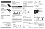
>25 cm
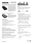
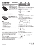
MX890 Wireless Desktop Base
The Shure MX890 desktop base for
MX405, MX410 and MX415 gooseneck
microphones offers cable-free installation
for corporate boardrooms or other applications requiring flexible microphone
configurations and MX415 miniature
gooseneck microphones are suitable for
boardrooms and other sites where aesthetics are important. The MX890 operates within the 518–937 MHz band and
is compatible with Shure SLX wireless
systems.
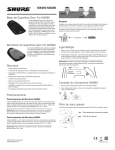
MX690 Wireless Boundary Microphone
The Shure MX690 microphone offers
cable-free installation for corporate boardrooms or other applications requiring flexible configurations. The MX690 operates
within the 518–937 MHz band and is compatible with Shure SLX wireless systems.
Features
• Sleek, low profile design
• Frequency agile, microprocessor controlled transmitter
>150 cm
MX690
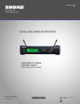
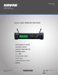
Receiver
Make sure the receiver is within sight of the transmitter. Do not place
receiver behind a metal barrier or any reflective surface.
Refer to the SLX Wireless System User Guide for more information, or visit www.shure.com.
30 m (100 ft)
Power On/Off
1. With the battery door open, press and hold the ON/OFF button
for approximately 2 seconds. Release the button when the LCD
screen illuminates.
2. To turn off the transmitter, press and hold the ON/OFF button
for approximately 2 seconds. Release the button when the LCD
screen is blank. The LEDs on the outside of the microphone will
also go dark.
Note: To power on the transmitter without opening the battery
compartment, press and hold the plastic ON/OFF button on the
battery door for approximately 2 seconds, then release it.
• IR link to SLX receiver for automatic frequency synchronization
• Programmable frequency Group/Channel display
• Programmable mute function
• Operates on two AA batteries
• Compatible with all Shure SLX Wireless systems
• MX890 Supports Shure MX405, MX410 and MX415 Mini Gooseneck
Microphones
• Commshield® technology for protection from RF interference
Placement
MX890 Microphone Placement
Place the MX890 no more than 25 cm (1 ft.) from the edge of the table.
Aim the microphone toward the talker and away from loudspeakers and
noise sources. Use one microphone for each talker. Pickup angle with a
cardioid cartridge is 130° at –3 dB. Pickup angle with a supercardioid cartridge is 115° at –3 dB.
Note: To minimize RF interference, maintain a distance of at least
0.3 m (1 ft.) between transmitters. In case of interference, increase
the distance between transmitters or change channels.
MX690 Microphone Placement
Place the MX690 within 1.5 m (5 ft.) of a talker. Aim the microphone toward the talkers and away from loudspeakers and noise sources. Use one
microphone for every two talkers. Pickup angle with a cardioid cartridge is
130° at –3 dB.
MX890 Connecting Gooseneck
1. Align the pin on the microphone flange with the slot on the desktop
base.
2. Insert the gooseneck into the desktop base and lock it in place by
rotating the gooseneck sleeve clockwise.
Low-Cut Filter
The low-cut filter attenuates frequencies below 150 Hz by 6 dB per
octave.
Filter disabled (as supplied)
Low-cut filter
Note: To minimize RF interference, maintain a distance of at least
0.3 m (1 ft.)
©2013 Shure Incorporated
27EN16692 (Rev. 3)
Printed in U.S.A.
Battery
To change between toggle and momentary:
Hold the PUSH button and press the SELECT button. (Test the microphone
to confirm the change.)
Installation
1. Open the battery compartment as shown.
Hold
2. Insert two 1.5 V "AA" batteries. Make sure the +/– terminals are properly oriented.
Note: Alkaline batteries last up to 8 hours. Rechargeable, carbonzinc, and zinc-chloride batteries provide less operating time.
To change between push-to-talk and push-to-mute:
1. Set the button for momentary operation.
2. Hold the SELECT button and press the PUSH button.
Hold
Power Meter
The battery meter on the LCD shows remaining battery life.
Mute Indicator
MX890
The desktop base illuminates the gooseneck microphone LED to indicate
whether the microphone is active or muted. Refer to the following table:
MX890 Status Indicator
Low Power Indicator
Steady Red: Power low. Replace batteries immediately
Pulsing Red: Batteries dead. Transmitter cannot be turned on until
batteries are replaced.
Microphone
Status
MX405 / MX410
Indicator
MX405R / MX410R Light
Ring
Active
Green
Red
Muted
Red/Flashing Green*
Off/Flashing*
*To toggle between off and flashing, press PUSH and ON/OFF simultaneously.
Mute Button
The mute button can be configured for toggle or momentary operation.
Toggle (as supplied)
The PUSH button toggles the microphone between active and muted states.
Note: The microphone always powers up in the active state.
Momentary
There are two types of momentary operation:
Push-to-Mute: The microphone is muted only while the button is pressed
and held.
Push-to-Talk: The microphone is active only while the button is pressed
and held.
United States, Canada, Latin
America, Caribbean:
Shure Incorporated
5800 West Touhy Avenue
Niles, IL 60714-4608 USA
Phone: 847-600-2000
Fax: 847-600-1212 (USA)
Fax: 847-600-6446
Email: [email protected]
www.shure.com
©2013 Shure Incorporated
MX690
The bi-color LED on the top of the microphone indicates whether the microphone is active or muted.
The LED can also be set to flash when muted.
MX690 Status Indicator
Display Mode
Status Indicator
Steady (as supplied)
Active = Green
Muted = Red
Flashing
Active = Green
Muted = Flashing Green
Europe, Middle East, Africa:
Shure Europe GmbH
Jakob-Dieffenbacher-Str. 12,
75031 Eppingen, Germany
Phone: 49-7262-92490
Fax: 49-7262-9249114
Email: [email protected]
Asia, Pacific:
Shure Asia Limited
22/F, 625 King’s Road
North Point, Island East
Hong Kong
Phone: 852-2893-4290
Fax: 852-2893-4055
Email: [email protected]
Locking Settings
Press ON/OFF and SELECT simultaneously to lock or unlock transmitter settings. When locked, the current settings cannot be manually changed.
Note: Locking the transmitter settings does not disable IR frequency
synchronization or the High Pass/Low Cut filter.
Troubleshooting
If you encounter difficulty with the SLX Wireless System
• Make sure both the transmitter and the receiver are turned on.
• Replace the battery if the battery LED is red.
• Make sure the Group/Channel settings for each transmitter-receiver
pair are identical.
• Make sure there is an unobstructed line of sight between the
transmitter and receiver.
• If necessary, reposition the receiver or decrease the distance between
transmitter and receiver.
• Remove local sources of RF interference, such as computers or
lighting equipment.
• Remove metal objects within 0.3 m (1 ft.) of the transmitter
Logic Mode
To use with a logic enabled receiver, you must perform an automatic sync.
The LCD flashes "log" during sync. Once in logic mode, the LCD flashes
"log" when powered up.
Note: Refer to the SLX Wireless System User Guide for complete
troubleshooting procedures.
Frequency Selection
Shure offers wireless systems in a selection of bands that conform to
the different government regulations of specific nations or geographic
regions. These regulations help limit radio frequency (RF) interference
among different wireless devices and prevent interference with local
public communications channels, such as television and emergency
broadcasts.
The system's band and frequency range are identified on the receiver
and transmitter. For example, "H4 518-578 MHz."
Automatic Frequency Synchronization
1. Power off all transmitters.
2. Begin with the first transmitter. Open the battery cover and power it on.
3. Begin with the first transmitter. Open the battery cover and power it on.
4. Aim the IR sensor at the first receiver IR port. The transmitter should
be no more than 15 cm (6 in.) from the receiver. Press and hold the
receiver SYNC button to send group and channel data to the transmitter.
The red LED on the transmitter will stop flashing when programming is
complete.
5. Power off the first transmitter and repeat the synchronization with each
additional transmitter and receiver pair.
Manual Frequency Synchronization
1. Press and hold the transmitter SELECT button until the desired group
number appears.
For information on bands available in your area, consult your local dealer
or phone Shure. More information is also available at www.shure.com.
LICENSING INFORMATION
Licensing: A ministerial license to operate this equipment may be required in certain areas. Consult your national authority for possible
requirements. Changes or modifications not expressly approved by
Shure Incorporated could void your authority to operate the equipment.
Licensing of Shure wireless microphone equipment is the user’s responsibility, and licensability depends on the user’s classification and application, and on the selected frequency. Shure strongly urges the user to
contact the appropriate telecommunications authority concerning proper
licensing, and before choosing and ordering frequencies.
Certifications
Certified under FCC Part 74.
Certified by IC in Canada under RSS-123 and RSS-102.
2. Press SELECT again and release it when the desired channel number
appears.
FCC: DD4MX890. IC: 616A-MX890.
Tips for Optimum Performance
The CE Declaration of Conformity can be obtained from: www.shure.com/
europe/compliance
• Maintain a direct line of sight between the transmitter and receiver
antennas.
• Avoid placing the transmitter on metal surfaces.
• Avoid placing laptop computers or other obstructions in front of the
microphone during use.
• Only use with a Shure SLX4L wireless receiver.
This product meets the Essential Requirements of all relevant European
directives and is eligible for CE marking.
Authorized European representative:
Shure Europe GmbH
Headquarters Europe, Middle East & Africa
Department: EMEA Approval
Jakob-Dieffenbacher-Str. 12
75031 Eppingen, Germany
Phone: 49-7262-92 49 0
Fax: 49-7262-92 49 11 4
Email: [email protected]
Specifications
Frequency Range and Transmitter
Output Level
Working Range
Line of Sight
30 m (100 ft)
Band
Range
Output Power
G4
470 to 494 MHz
30 mW
G5
494 to 518 MHz
30 mW
H5
518 to 542 MHz
30 mW
J3
572 to 596 MHz
30 mW
Power Requirements
2 LR6 AA batteries, 1.5 V, alkaline
L4
638 to 662 MHz
30 mW
Power Consumption
@3 V
P4
702 to 726 MHz
30 mW
Q4
740 to 752 MHz
10 mW
R13
794 to 806 MHz
20 mW
R5
800 to 820 MHz
20 mW
JB
806 to 810 MHz
10 mW
S6
838 to 865 MHz
10 mW
X4
925 to 932 MHz
10 mW
X7
925 to 937.5 MHz
10 mW
Note: Actual range depends on RF signal absorption, reflection and interference.
Frequency Stability
±10 ppm
Modulation
FM, 45 kHz max. deviation
Display backlight on 220 mA, ±30 mA
Display backlight off 175 mA, ±30 mA
Power Consumption (X4, X7)
@3 V
Display backlight on 245 mA, ±30 mA
Display backlight off 200 mA, ±30 mA
Battery Life
>8 hours (alkaline)
IMPORTANT SAFETY INSTRUCTIONS
Operating Temperature Range
-18°C (0°F) to +57°C (135°F)
2. KEEP these instructions.
1. READ these instructions.
3. HEED all warnings.
Note: Battery characteristics may limit this range.
4. FOLLOW all instructions.
Dimensions
43 mm x 87 mm x 148 mm (H x W x D)
5. DO NOT use this apparatus near water.
6. CLEAN ONLY with dry cloth.
Weight
MX690
MX890
Net
319 g (11.2 oz.)
312 g (11 oz.)
Packaged
516 g (18.2 oz.)
530 g (18.7 oz.)
7. DO NOT block any ventilation openings. Allow sufficient distances for adequate ventilation and
install in accordance with the manufacturer’s instructions.
8. DO NOT install near any heat sources such as open flames, radiators, heat registers, stoves, or
other apparatus (including amplifiers) that produce heat. Do not place any open flame sources
on the product.
9. DO NOT defeat the safety purpose of the polarized or groundingtype plug. A polarized plug
has two blades with one wider than the other. A grounding type plug has two blades and a third
grounding prong. The wider blade or the third prong are provided for your safety. If the provided
plug does not fit into your outlet, consult an electrician for replacement of the obsolete outlet.
10.PROTECT the power cord from being walked on or pinched, particularly at plugs, convenience
receptacles, and the point where they exit from the apparatus.
11.ONLY USE attachments/accessories specified by the manufacturer.
12.USE only with a cart, stand, tripod, bracket, or table specified by the manufacturer, or sold with
the apparatus. When a cart is used, use caution when moving the cart/apparatus combination to
avoid injury from tip-over.
13.UNPLUG this apparatus during lightning storms or when unused for long periods of time.
14.REFER all servicing to qualified service personnel. Servicing is required when the apparatus
has been damaged in any way, such as power supply cord or plug is damaged, liquid has been
spilled or objects have fallen into the apparatus, the apparatus has been exposed to rain or
moisture, does not operate normally, or has been dropped.
15.DO NOT expose the apparatus to dripping and splashing. DO NOT put objects filled with liquids,
such as vases, on the apparatus.
16.The MAINS plug or an appliance coupler shall remain readily operable.
17.The airborne noise of the Apparatus does not exceed 70dB (A).
18.Apparatus with CLASS I construction shall be connected to a MAINS socket outlet with a protective earthing connection.
19.To reduce the risk of fire or electric shock, do not expose this apparatus to rain or moisture.
20.Do not attempt to modify this product. Doing so could result in personal injury and/or product
failure.
21.Operate this product within its specified operating temperature range.
This symbol indicates that dangerous voltage constituting a risk of electric shock is present
within this unit.
This symbol indicates that there are important operating and maintenance instructions in the
literature accompanying this unit.
WARNING: Voltages in this equipment are hazardous to life. No user-serviceable parts inside. Refer all servicing to qualified service personnel. The safety certifications do not apply
when the operating voltage is changed from the factory setting.
WARNING: This product contains a chemical known to the State of California to cause cancer and birth defects or other reproductive harm.