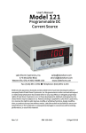
1
USER’S MANUAL
Model 818 / 819
Cryopump Monitor
Curve 0
Curve 1
Curve 2
Curve 3
Curve 4
Curve 5
Curve 6
Curve 7
Curve 8
Curve 9
DT-500DI-8B
DT-500DI-8A
DT-500DRC-D
DT-500DRC-E1
CTI Curve C
DT-500DI-8C
DT-470 Curve 10
User Selectable Curve
User Selectable Curve
User Selectable Curve
Lake Shore Cryotronics, Inc.
575 McCorkle Blvd.
Westerville, Ohio 43082-8888 USA
E-Mail Addresses:
[email protected]
[email protected]
Visit Our Website:
www.lakeshore.com
Fax: (614) 891-1392
Telephone: (614) 891-2243
Methods and apparatus disclosed and described herein have been developed solely on company funds of Lake Shore Cryotronics, Inc.
No government or other contractual support or relationship whatsoever has existed which in any way affects or mitigates proprietary
rights of Lake Shore Cryotronics, Inc. in these developments. Methods and apparatus disclosed herein may be subject to U.S. Patents
existing or applied for. Lake Shore Cryotronics, Inc. reserves the right to add, improve, modify, or withdraw functions, design
modifications, or products at any time without notice. Lake Shore shall not be liable for errors contained herein or for incidental or
consequential damages in connection with furnishing, performance, or use of this material.
Rev. 1.2
P/N 119-003
13 April 1999
Lake Shore Model 818 / 819 Cryopump Monitor User’s Manual
LIMITED WARRANTY
Lake Shore Cryotronics, Inc. (henceforth Lake Shore), the manufacturer, warrants the instrument and probes
to be free from defects in material and workmanship for a period of twelve months from the date of shipment.
During the warranty period, under authorized return of instruments or component parts to Lake Shore freight
prepaid, the company will repair, or at its option replace, any part found to be defective in material or
workmanship, without charge to the Owner for parts, service labor or associated customary shipping cost.
Replacement or repaired parts are warranted for only the unexpired portion of the original warranty.
All products are thoroughly tested and calibrated to published specifications prior to shipment. Calibration
Certifications are offered for six month periods only. To update such documentation, Lake Shore offers a recertification service at reasonable cost.
LIMITATION OF WARRANTY
This warranty is limited to Lake Shore products purchased and installed in the United States, or Internationally
through our approved distribution agents. This same protection will extend to any subsequent owner during
the warranty period. It does not apply to damage resulting from improper or inadequate maintenance,
unauthorized modification or misuse, operation outside of the environmental specifications, or from buyersupplied software interfacing. It does not apply to damage caused by accident, misuse, fire, flood or Acts of
God, or from failure to properly install, operate, or maintain the product in accordance with the printed
instruction provided.
This warranty is in lieu of any other warranties, expressed or implied, including merchantability or fitness for a
particular purpose, which are expressly excluded. the owner agrees that Lake Shore’s liability with respect to
this product shall be set forth in this warranty, and incidental or consequential damages are expressly
excluded.
CERTIFICATION
Lake Shore certifies that this product has been inspected and tested in accordance with its published
specifications and that this product met its published specifications at the time of shipment. The accuracy and
calibration of this product at the time of shipment are traceable to the United States National Institute of
Standards and Technology (NIST); formerly known as the National Bureau of Standards (NBS), or to a
recognized natural standard.
TRADEMARK ACKNOWLEDGMENT
Many of the designations used by manufacturers and sellers to distinguish their products are claimed as
trademarks. Where those designations appear in this manual and Lake Shore was aware of a trademark
®
claim, the designations have been printed in initial capital letters and the ™ or symbol used.
CalCurve™, Carbon-Glass™, Cernox™, Duo-Twist™, Gamma Probe™, Quad-Lead™, and Quad-Twist™
are trademarks of Lake Shore Cryotronics, Inc.
Copyright © 1988 – 1999 by Lake Shore Cryotronics, Inc. All rights reserved. No portion of this manual may be
reproduced, stored in a retrieval system, or transmitted, in any form or by any means, electronic, mechanical,
photocopying, recording, or otherwise, without the express written permission of Lake Shore.
A
Lake Shore Model 818 / 819 Cryopump Monitor User’s Manual
TABLE OF CONTENTS
Chapter/Paragraph
1
2
3
4
5
Title
Page
INTRODUCTION ............................................................................................................................
1-1
1.1
1.2
GENERAL ...................................................................................................................
DESCRIPTION ............................................................................................................
1-1
1-1
INSTALLATION ..............................................................................................................................
2-1
2.1
2.2
2.3
2.4
2.4.1
2.4.2
2.5
2.5.1
2.5.2
2.5.3
2.5.4
GENERAL ...................................................................................................................
INSPECTION AND UNPACKING................................................................................
REPACKAGING FOR SHIPMENT ..............................................................................
POWER AND GROUNDING REQUIREMENTS.........................................................
Power Requirements................................................................................................
Power Cord and Grounding Requirements ..............................................................
SENSOR AND INTERFACE CONNECTIONS............................................................
J1 Sensor Input Connections ...................................................................................
J2 Serial I/O..............................................................................................................
J3 Alarms .................................................................................................................
J4 Monitors...............................................................................................................
2-1
2-1
2-1
2-1
2-1
2-1
2-2
2-2
2-2
2-2
2-2
OPERATING INSTRUCTIONS.......................................................................................................
3-1
3.1
3.2
3.3
3.4
3.4.1
3.5
3.5.1
3.5.2
3.5.3
3.5.4
3.6
3.6.1
3.6.2
GENERAL ...................................................................................................................
CONTROLS AND INDICATORS.................................................................................
VOLTAGE AND TEMPERATURE DISPLAY...............................................................
STANDARD CURVES.................................................................................................
Curve and Alarm Action Selection............................................................................
ALARM OPERATION ..................................................................................................
Observing the Alarm Setpoint ..................................................................................
Alarm Action .............................................................................................................
Latching or Non-Latching HI and LO Alarms ...........................................................
Setting the HI and LO Alarms...................................................................................
CHANNEL SELECTION FOR THE MODEL 819 ........................................................
Channel Scan...........................................................................................................
Setting the Dwell Time for a Given Channel ............................................................
3-1
3-1
3-2
3-2
3-2
3-2
3-2
3-3
3-3
3-4
3-4
3-4
3-4
REMOTE OPERATION ..................................................................................................................
4-1
4.1
4.2
4.2.1
4.2.2
4.2.3
4-1
4-1
4-1
4-2
4-3
RS-232C SERIAL INTERFACE...................................................................................
INTERFACE COMMANDS..........................................................................................
Display and Alarm Parameter Commands...............................................................
Output Request Commands.....................................................................................
Model 819 Scan Parameter Commands ..................................................................
MAINTENANCE
5.1
5.2
5.3
5.4.1
5.4.2
FUSE REPLACEMENT ...............................................................................................
LINE VOLTAGE SELECTION .....................................................................................
CALIBRATION.............................................................................................................
Current Source Calibration ..........................................................................................
A/D Converter Calibration............................................................................................
5-1
5-1
5-1
5-1
5-2
APPENDIX A – Curve Information
APPENDIX B – Model 818/819 Mounting Adapter
APPENDIX C – Sample RS-232 Quick Basic Communication Program
Table of Contents
i
Lake Shore Model 818 / 819 Cryopump Monitor User’s Manual
LIST OF ILLUSTRATIONS
Figure No.
Title
Page
2-1
Sensor Connections..................................................................................................................
2-2
3-1
3-2
Model 818 and 819 Cryopump Monitor Front Panels ...............................................................
Model 818 and 819 Cryopump Monitor Rear Panels ................................................................
3-1
3-1
B-1
Model 818/819 Mounting Detail.................................................................................................
4-6
LIST OF TABLES
Table No.
Title
Page
1-1
Model 818 and 819 Specifications ............................................................................................
1-2
2-1
2-2
2-3
Sensor Connections for the J1 INPUTS ...................................................................................
Serial I/O Connections ..............................................................................................................
J4 Monitors Connections...........................................................................................................
2-2
2-2
2-2
3-1
3-2A
3-2B
Standard Curves and Alarm Temperature Limits .....................................................................
Alarm Action 0 (818) .................................................................................................................
Alarm Action 1 (DIGI-K) ............................................................................................................
3-2
3-3
3-3
A-1
A-2
A-3
A-4
A-5
A-6
A-7
Curve #0: DT-500DI-8B Voltage/Temperature Characteristics ................................................
Curve #1: DT-500DI-8A Voltage/Temperature Characteristics ................................................
Curve #2: DT-500DRC-D Voltage/Temperature Characteristics ..............................................
Curve #3: DT-500DRC-E1 Voltage/Temperature Characteristics ............................................
Curve #4: CTI Diode Voltage/Temperature Characteristics......................................................
Curve #5: DT-500DI-8C Voltage/Temperature Characteristics ................................................
Curve #6: DT-470 Voltage/Temperature Characteristics..........................................................
A-1
A-2
A-3
A-4
A-5
A-6
A-7
ii
Table of Contents
Lake Shore Model 818 / 819 Cryopump Monitor User’s Manual
CHAPTER 1
INTRODUCTION
1.1
GENERAL
The information contained in this manual pertains to the installation, operation, remote programming, options
and accessories and calibration procedures for the Lake Shore Cryotronics, Inc. Model 818 and 819
Cryopump Monitors and the Balzers TMU-121 Cryopump Monitor.
NOTE: The TMU-121 is identical to the Model 818 except for the addition of a back panel keylock switch.
Users may wire two silicone diode sensors directly to the TMU-121; the keylock switch selects which input to
display. All other front panel and RS-232 operation is identical to the Model 818.
1.2
DESCRIPTION
The Model 818/819 is a microprocessor controlled instrument which provides direct digital display of
temperature with up to 4 digits of resolution in K, °C or °F and sensor voltage to 1 mV.
The Model 818 features one input with two alarms. The alarms can be used to safeguard or initiate and control
automatic cryopump regeneration cycles. The alarms are configured as HI and ID alarms. Set alarm setpoints
from the front panel with function keys and up/down keys, or simply check them without changing their values.
The alarm setpoint resolution is 0.1 K, °C or °F over the sensor temperature range. Table 3-1 describes
sensor temperature ranges. For security, the up/down keys can be deactivated by a rear panel DIP switch.
A deadband around each setpoint reduces or eliminates relay contact chattering.
The Model 819 features four inputs with two alarms (as described above) for each input. The Model 819 can
also scan between channels with dwell times of 0 (skip), 5, 10, 30 or 60 seconds for each channel.
The Model 818/819 directly reads temperature from Lake Shore DT-470 or DT-500 Series Temperature
Sensors. All DT-470 sensors follow the same temperature response curve and come in four bands of tracking.
Low temperature (2 to 100K) accuracies range from 0.25K for band 11 to 1K for band 13. The units have a
specified temperature range of 4 to 475 K with DT-470 sensors and 4 to 325 K with DT-500 sensors.
Diode sensor voltages are digitized with a resolution of 100 mV out of 3 volts full scale. The accuracy of the
electronics with DT-470 sensors is better than ±0.01 K below 28K and ±0.1K above 28K. The equivalent
display temperature rounds to 0.1 above 100 (any units) and 0.01 below 100.
The Model 818/819 features an RS-232C Serial Interface which allows users to monitor temperature, and
monitor and change alarm setpoints from a host computer. Sensor input(s), alarm contacts, and RS-232C
lines are located on the instrument rear panel.
Introduction
1-1
Lake Shore Model 818 / 819 Cryopump Monitor User’s Manual
Table 1-1. Model 818/819 Specifications
THERMOMETRY:
Inputs: 818 = one; 819 = four.
Measurement Type: Isolated 4-lead.
Sensor (order separately): Lake Shore DT-470 or DT-500 Series Silicon Diode Sensors.
Sensor Temperature Coefficient: Negative
Sensor Units: Volt (V)
Input Range: 0 to 3 volts
Sensor Excitation (constant current): 10 µA ±0.01%
Update Rate: 818 = One reading per 0.6 second; 819 = One reading per 0.6 second continuous. 1.2 seconds on
channel change.
Scan Dwell Time: 818 = not applicable; 819 = 0(skip), 5, 10, 30, 60 seconds for each channel.
Example Lake Shore Sensor: DT-470-CO-11
Sensor Temperature Range: 1.4 to 475 K.
Standard Curve: Curve 10, DT-500DI-8A, DT-500DI-8B, DT-500DI-8C, DT-500DRC-D, DT-500DRC-E1, CTI Curve C
Typical Sensor Sensitivity: -30 mV/K at 4.2 K
-1.9 mV/K at 77 K
-2.3 mV/K at 300 K
-2.2 mV/K at 475 K
Measurement Resolution:
Sensor Units:
Temperature Equivalence:
Measurement Accuracy:
Sensor Units:
Temperature Accuracy:
Measurement Temperature Coefficient:
Sensor Units (% reading/°C ambient): 0.0075%/°C
Temperature Equivalence:
4 mK/°C at 4.2 K
40 mK/°C at 77 K
20 mK/°C at 300 K
3 mK/°C at 475 K
±0.3 mV ±0.04% of reading
±0.3 K at 4.2 K
±0.62 K at 77 K
±0.72 K at 300 K
±1.2 K at 475 K
0.1 mV
4 mK/°C at 4.2 K
53mK/°C at 77 K
42 mK/°C at 300 K
46 mK/°C at 475 K
Magnetic Field Use: Recommended T ≥ 40 K and B ≤ 5 T
ALARMS:
Number of Alarms: 818 = Two; 819 = Eight - two per channel
Alarm Type: One high and one low per channel
Alarm Deadband: ±0.25 K above 100; ±0.025 K below 100
Alarm Contact: One normally open and one normally closed relay contact per alarm, UL rated at 250 VAC or
30 VDC at 5 A, 110 VDC at 0.6 A.
FRONT PANEL:
Sensor Display: 4-digit LED display in voltage or temperature (K, °C, °F).
Annunciators: 818 = Alarm Status, Channel, Units; 819 = Alarm Status, Channel, Units, Scan
Display Resolution: 0.1 degree above 100 (any units), 0.01 degree below 100; voltage to 0.001 mV.
Keys: 818 = HI/LO Alarm, s, t; 819 = Channel, HI/LO Alarm, s, t
INTERFACE:
Serial Interface: RS-232C electrical format, 300 baud, RJ-11 connector
Linearized Analog Output: 818 = 0 to 1 volt represents 0 to 1000 K; 819 = not applicable
GENERAL:
Ambient Temperature Range: 15 to 35 °C
Power: 90-125 or 210-250 VAC (selected via rear panel switch), 50 or 60 Hz. 818: 7 VA; 819: 10 VA.
Dimensions: 105 x 132 x 254 mm (4.125 x 5.25 x 10 inches); Panel mount, ¼ EIA.
Weight: 1.6 kilograms (3.5 pounds)
1-2
Introduction
Lake Shore Model 818 / 819 Cryopump Monitor User’s Manual
CHAPTER 2
INSTALLATION
2.1
GENERAL
This chapter covers Inspection and Unpacking (Paragraph 2.1), Repackaging for Shipment (Paragraph 2.2),
Power and Ground Requirements (Paragraph 2.3), and Sensor and Interface Connections (Paragraph 2.4).
2.2
INSPECTION AND UNPACKING
Inspect shipping containers for external damage. Make all claims for damage (apparent or concealed) or
partial loss of shipment in writing to Lake Shore within five (5) days from receipt of goods. If damage or loss is
apparent, please notify the shipping agent immediately.
Open the shipping containers. Use the packing list included with the system to verify receipt of the instrument,
sensor, accessories, and manual. Inspect for damage. Inventory all components supplied before discarding
any shipping materials. If there is freight damage to the instrument, file proper claims promptly with the carrier
and insurance company and notify Lake Shore. Notify Lake Shore immediately of any missing parts. Lake
Shore cannot be responsible for any missing parts unless notified within 60 days of shipment. See the
standard Lake Shore Warranty on the A Page (immediately behind the title page).
2.3
REPACKAGING FOR SHIPMENT
To return the Model 818/819 or accessories for repair or replacement, obtain a Return Goods Authorization
(RGA) number from Technical Service in the United States, or from the authorized sales/service
representative from which the product was purchased. Instruments may not be accepted without a RGA
number. When returning an instrument for service, Lake Shore must have the following information before
attempting any repair.
1.
2.
3.
4.
5.
Instrument model and serial number.
User name, company, address, and phone number.
Malfunction symptoms.
Description of system.
Returned Goods Authorization (RGA) number.
Repack the system in its original container (if available). Affix shipping labels and FRAGILE warnings. Write
RGA number on the outside of the container or on the packing slip. If not available, consult Lake Shore for
shipping and packing instructions.
2.4
2.4.1
POWER AND GROUNDING REQUIREMENTS
Power Requirements
The Model 818/819 requires a power source of 50 to 60 Hz single phase 90-125 or 210-250 VAC. For the
Model 818, replace the fuse with 0.25 A for 110 VAC operation, or 0.125 A for 230 VAC operation. For the
Model 819, replace the fuse with 0.5 A for 110 VAC operation, or 0.25 A for 230 VAC operation.
CAUTION: Verify rear panel line voltage selection switch (Figure 3-2, Key 2) matches AC voltage
source. Verify proper fuse installation before inserting power cord and turning on instrument.
2.4.2
Power Cord and Grounding Requirements
A three-prong detachable power cord for 120 VAC operation which mates with the rear panel UL/IEC/ICEE
Standard plug ships with the instrument.
To protect operating personnel, the National Electrical Manufacturer's Association (NEMA) recommends, and
some local codes require, instrument panels and cabinets be grounded. The three-prong power cable, when
plugged into an appropriate receptacle, grounds the instrument.
Installation
2-1
Lake Shore Model 818 / 819 Cryopump Monitor User’s Manual
2.5
2.5.1
SENSOR AND INTERFACE CONNECTIONS
J1 Sensor Input Connections
The Model 818 has one rear panel 5-pin sensor input connector
designated J1 INPUT 1. The Model 819 has four rear panel 5-pin sensor
input connectors designated J1-1, J1-2, J1-3 and J1-4 for inputs 1 thru 4.
Table 2-1 lists sensor lead connection definitions and Figure 2-1
illustrates them.
Table 2-1. Sensor Connections
for the J1 INPUTS
Terminal
Description
A
+ Current Out
B
- Current Out
Use four wire connection (Figure 2-1A) to avoid IR drops in the voltage
sensing pair resulting in temperature measurement error. Use two wire
connection (Figure 2-1B) in less critical applications where lead
resistance is small, and small readout errors can be tolerated.
D
- Voltage Sense
E
+ Voltage Sense
D (-V)
B (-I)
2.5.2
E (+V)
D (-V)
B (-I)
J2 Serial I/O
The RS-232C Serial Interface connector is a rear panel mounted RJ-11
modular socket. The connector pins are numbered 1 thru 6 from left to
right. Table 2-2 lists connector pin assignments.
NOTE: When converting from the RJ-11 to DB-25 connector, pins 5, 6, 8
and 20 of the DB-25 connector may need to be shorted together for
proper interface operation.
2.5.3
SENSOR
E (+V)
SENSOR
Lake Shore QUAD-LEAD™ 36 Gauge Cryogenic wire is ideal for sensor
H
Shield
connections since the four color-coded leads run together. The wire is
Phosphor Bronze with a Formvar insulation and
Figure 2-1. Sensor Connections
Butryral bonding between the four leads. Color coding
is red, green, clear and blue for easy wire
A: Four-Lead Sensor Hookup
B: Two-Lead Sensor Hookup
identification.
A (+I)
A (+I)
Table 2-2. Serial I/O Connections
Pin #
Description
1 and 2
Received Data
3 and 4
Signal Ground
5 and 6
Transmitted Data
J3 Alarms
The HI and LO alarm contacts are present on rear panel card edge connections. The Model 818 has one
6-contact card edge connector for the HI and LO alarms. The Model 819 has one 6-contact card edge for
Input 1 HI and LO alarms and one 18-contact card edge connector for Input 2 thru Input 4 HI and LO alarms.
The top and bottom contacts of the card edge are identical in definition and the mating connector supplied
shorts them together. The SPDT alarm contacts are in groups of three: 1 - COM - 2 or NO - lH - NC
representing the contacts for the Input 1 HI alarm. 1 or NO represents the (N)ormally (O)pen state; 2 or NC
represents the (N)ormally (C)losed state. The card edge is slotted between pins 2 and 3 to allow for mating
connector keying. Chapter 3 details alarm action.
2.5.4
J4 Monitors
With an Model 818-MN or 818-LA Option, the J4 Monitors connector is
present. Table 2-3 lists connector pin assignments.
2-2
Table 2-3. J4 Monitors
Connections
Terminal
Description
A
V+ MN Output
B
V- MN Output
D
V+ LA Output
E
V- LA Output
H
Shield
Installation
Lake Shore Model 818 / 819 Cryopump Monitor User’s Manual
CHAPTER 3
OPERATION
3.1
GENERAL
This chapter covers Controls and Indicators (Paragraph 3.2), Voltage or Temperature Display (Paragraph 3.3),
Standard Curves (Paragraph 3.4), Alarm Operation (Paragraph 3.5), and Channel Selection for the Model 819
(Paragraph 3.6).
3.2
CONTROLS AND INDICATORS
Note: The unit completes an internal update cycle of between ¼ and ½ second before responding to a front
panel key entry. A key pressed for less than ½ second may be ignored.
818 CRYOPUMP MONITOR
7
HI
LO
K
°C
°F
V
±
819 CRYOPUMP MONITOR
5
6
1
2
3
4
1
2
5
K
°C
°F
V
±
SCAN 1H
1L
2H
2L
3H
3L
6
4H
4L
7
CHANNEL
3
4
HI ALARM
s
LO ALARM
t
8
4
HI ALARM
s
LO ALARM
t
Lake Shore Cryotronics
Lake Shore Cryotronics
1.
2.
3.
4.
8
Active Channel Indicators
SCAN Indicator
CHANNEL Key
HI ALARM and LO ALARM Keys
5.
6.
7.
8.
Four-Digit Display
Units Indicators (V, K, °C, °F)
HI and LO Alarm Status Indicators (One for each channel)
Increment (s) and Decrement (t) Keys
Figure 3-1. Model 818 and 819 Cryopump Monitor Front Panels
1
7
J1 INPUT 1
A
2
B
A
2
B
8
H
D
E
D
9
4
J2 SERIAL I/O
J3 ALARMS
LO
HI
1-COM-2 1-COM-2
I ADJ CAL
6
1.
2.
3.
4.
5.
6.
7.
*
CURVE SET
ALARM LATCH
ALARM SET
A
B
A
H
E
B
A
B
H
D
E
J1-1
J1-2
A
H
D
E
J1-3
B
H
D
E
D
J1-4
3
4
10
5
7
J1 INPUTS
J4 MONITORS
H
E
1
9
NO-2L-NC NO-2H-NC NO-3L-NC NO-3-NC NO-4L-NC NO-4H-NC
J3 ALARMS
NO-1L-NC NO-1H-NC
I ADJ CAL
5
6
Line Cord Receptacle with Fuse and ON/OFF Switch
J1 Inputs: Input 1 (818); J1-1, J1-2, J1-3, J1-4 (819)
J3 Alarms: Channels 2, 3, and 4 LO and HI Outputs
I ADJ: Current Source Adjustment Potentiometer
J3 Alarms: Channel 1 LO and HI Outputs
CAL: Calibration Enable Button
115/230 AC Voltage Selection Switch
10
J2 SERIAL I/O
*
CURVE SET
ALARM LATCH
ALARM SET
8. J4 MONITORS Connector
9. 4-Position Configuration DIP Switch:
Switch 1 - Reserved (*)
Switch 2 - Alarm Latch
Switch 3 - Alarm Set
Switch 4 - Curve Set
10. J2 SERIAL I/O: Serial Interface
Figure 3-2. Model 818 and 819 Cryopump Monitor Rear Panels
Operation
3-1
Lake Shore Model 818 / 819 Cryopump Monitor User’s Manual
3.3
VOLTAGE OR TEMPERATURE DISPLAY
The Model 818 and 819 Cryopump Monitors read in voltage or temperature (kelvin, Celsius, or Fahrenheit).
To change units, press the s key or the t key or send a command over the RS-232C Serial Interface.
3.4
STANDARD CURVES
The unit stores several standard curves. Different curves may be assigned to each channel of the Model 819.
These curves, numbered 0 thru 9, are listed on the front cover of this manual as well as in Table 3-1. The front
cover also indicates the factory curve configuration of the unit. Curve 6 (DT-470 Curve 19) is the standard
curve selected unless specified differently upon ordering. Tables of voltage versus temperature for these
standard curves appear in Appendix A.
3.4.1
Curve and Alarm Action Selection
To change or check the selected curve or alarm action, use the procedure below:
1. For the Model 819, press the CHANNEL key and the s or t key until the desired channel displays.
2. Turn ON (1) DIP switch number 4 on the instrument rear marked CURVE SET.
3. Note the display now shows the number 0 or 1 on the left (alarm action) and a number between 0 and 9
on the right (standard curve).
4. To change the curve, push either the s or t key until the desired curve number displays. If a curve is not
present, it is skipped in the sequence. To select the alarm action push the LO ALARM key (0) for the
Model 818 operation or the HI ALARM key (1) for DIGI-K operation.
5. Turn OFF (0) DIP switch number 4 on the instrument rear marked CURVE SET. The instrument returns to
normal operation with the new curve and alarm action selected.
Note: A different curve can be assigned to each of the four Model 819 channels independently. However,
the alarm action applies to all four channels.
Table 3-1. Standard Curves and Alarm Temperature Limits
3.5
Curve #
Description
Temp Range (K)
0
DT-500D1-8B
0 - 324.9
1
DT-500D1-8A
0 - 324.9
2
DT-5OODRC-D
0 - 324.9
3
DT-5OODRC-El
0 - 324.9
4
CTI Curve C
0 - 324.9
5
DT-500D1-8C
0 - 324.9
6
DT-470 Curve 10
0 - 474.9
7
—
—
8
—
—
9
—
—
ALARM OPERATION
The Model 818 can set two alarm trip points (HI and LO) associated with the single sensor input. The Model
819 has four sensor inputs and two alarm trip points (HI and LO) for each input.
The deadband is ±0.025 for the setpoint less than 100 (any units) and ±0.25 for the setpoint greater than 100.
If the display is in voltage, then the deadband assumes appropriate kelvin units.
3-2
Operation
Lake Shore Model 818 / 819 Cryopump Monitor User’s Manual
3.5.1
Checking the Alarm Setpoints
To check the HI alarm setpoint, press the front panel HI ALARM key. The HI alarm setpoint displays in the
chosen temperature units. If the units are V (volts), the units indicator changes to K (kelvin) and the setpoint
displays in kelvin. Similarly, to check the LO alarm, press the LO ALARM key.
3.5.2
Alarm Action
The Model 818 and 819 have two different alarms that can be selected when the sensor curve is selected.
Alarm action 0 is the Model 818 operation and alarm action 1 is the DIGI-K operation. See Table 3-2A and
3-2B for a truth tables of the respective alarm actions.
Table 3-2A. Alarm Action 0 (Model 818)
Contact Positions
Display Reading Compared to:
LO Alarm
HI Alarm
LO Alarm
HI Alarm
NO - COM
COM - NC
NO - COM
COM - NC
Higher
Higher
Open
Closed
Closed
Open
Higher
Lower
Open
Closed
Open
Closed
Lower
Higher
Closed
Open
Closed
Open
Lower
Lower
Closed
Open
Open
Closed
Open
Closed
Open
Closed
Power OFF
Table 3-2B. Alarm Action 1 (DIGI-K)
Contact Positions
Display Reading Compared to:
HI Alarm
LO Alarm
HI Alarm
NO - COM
COM - NC
NO - COM
COM - NC
Higher
Higher
Closed
Open
Closed
Open
Higher
Lower
Closed
Open
Open
Closed
Lower
Higher
Open
Closed
Closed
Open
Lower
Lower
Open
Closed
Open
Closed
Open
Closed
Open
Closed
Power OFF
3.5.3
LO Alarm
Latching or Non-Latching HI and LO Alarms
When the rear panel ALARM LATCH DIP switch is OFF (0), relays close or open as specified in Table 3-2.
If the sample sensor temperature oscillates around the HI or LO alarm setpoint temperature, then the relay
opens and closes in an oscillatory fashion following the alarm action. There is a deadband around the setpoint
as specified in Paragraph 3.5 to eliminate chattering of relay contacts.
When the ALARM LATCH switch is ON (1), the alarm relays take on a latching configuration. When the
sample sensor temperature forces the alarm to go from NO to NC, the relays remain closed. There are three
ways to reopen the relay.
1. From the Front Panel: hold the HI ALARM and LO ALARM keys down for more than 2 seconds. The
ALARM STATUS light(s) go out indicating alarms are reopened.
2. From the Rear Panel: disable the MARK LATCH switch (Configuration DIP Switch 2) momentarily.
3. Send the R (RESET) command over the RS232C interface.
Operation
3-3
Lake Shore Model 818 / 819 Cryopump Monitor User’s Manual
3.5.4
Setting the HI and LO Alarms
The alarms may be changed if the rear panel ALARM SET switch (Configuration DIP Switch 3) is ON (1). To
change the alarms from the front panel:
1. Turn ON (1) rear panel configuration DIP Switch 3, marked ALARM SET.
2. Press either the HI ALARM or LO ALARM key and check the displayed alarm setting. To change the
setting, push either the s or t key until the desired setting is reached. Note: the alarms can only be set in
temperature. If voltage is the display units, the display defaults to kelvin if an alarm key is pushed. The
alarm setpoint resolution is 0.1 K, °C or °F. The alarm setpoint is bounded by the sensor temperature
range listed in Table 3-1.
3. For the Model 819, press the CHANNEL key and the s or t key until the desired channel is reached,
then implement step 2.
4. The alarms take on the new values immediately. The ALARM SET switch only deactivates the ability to
set the alarms if it is in the OFF (0) position.
3.6
MODEL 819 CHANNEL SELECTION
The Model 819 has four sensor inputs (or channels) numbered 1 thru 4. To change the display input, press the
CHANNEL key and either the s or t key. The channel input position displays to the left of the display. Hold
the CHANNEL key for greater than one second to toggle the scan mode, and greater than two seconds to
display the dwell time for the selected channel.
3.6.1
Channel Scan
In hold mode, the Model 819 internally scans each channel and updates alarms approximately every
8 seconds. In scan mode, the Model 819 continuously monitors the displayed channel and updates its alarms
only. If a channel is excluded from the scan sequence (its dwell time is set to 0), the alarms of this channel are
not updated. To enable or disable the scan, hold the CHANNEL key in for greater than one second. The
Model 819 enters the SCAN mode as indicated by the SCAN annunciator.
3.6.2
Setting Channel Dwell Time
To set the dwell time for a given channel, hold in the CHANNEL key for greater than two seconds and use the
s or t keys to increment or decrement the dwell times between 0 (skip), 5, 10, 30 and 60 seconds. Next
increment the channel and repeat the dwell time setting process.
3-4
Operation
Lake Shore Model 818 / 819 Cryopump Monitor User’s Manual
CHAPTER 4
REMOTE OPERATION
4.1
RS-232C SERIAL INTERFACE
The Models 818 and 819 feature a serial RS-232C interface which allows communication with a host
computer (see Table 4-1 below):
Table 4-1. Model 818/819 RS-232C Interface Specifications
Transmission: Three Wire
Connector: RJ-ll Modular Socket
Timing Format: Asynchronous
Transmission Mode: Half Duplex
Baud Rate: 300
4.2
Bits per Character: 7 (not including start, stop or parity bits)
Parity Type: odd
Number of Stop Bits: 1
Data Interface Levels: Transmits/Receives using EIA voltage levels
INTERFACE COMMANDS
The paragraphs below define RS-232C Interface Commands and their format. Enter switch and channel IDs
as integers (no decimal point). Enter temperatures to 0.1 degrees. If entered with greater precision, they
truncate to the nearest 0.1 degree. Enter temperatures with or without a decimal point. For example, any of
the following are valid temperature entries: 5, 5.0, 24, 98.3, 235. Temperature is bounded by upper and lower
sensor limits listed in Table 3-1.
4.2.1
F0
Display and Alarm Parameter Commands
Select Display Units
Input:
F0K, F0C, F0F, or F0V
Returned: Nothing.
Remarks: Sets display units to Kelvin (K), Celsius (C), Fahrenheit (F), or Volts (V).
H
Set High Alarm Setpoint.
Input:
Model 818: H<Temperature>, Model 819: <Channel>H<Temperature>
Returned: Nothing.
Remarks: Sets the High Alarm setpoint. Channel = 0 to 4. Example: For a setpoint of 300° on the
Model 818, type H300. For a setpoint of 31.2° on channel 3 on the Model 819, type 3H31.2.
Select temperature units from the unit keyboard or by using the F0 command.
L
Set Low Alarm Setpoint.
Input:
Model 818: L<Temperature>, Model 819: <Channel>L<Temperature>
Returned: Nothing.
Remarks: Sets the Low Alarm setpoint. Channel = 0 to 4. Example: For a setpoint of 21.1° on the
Model 818, type L21.1. For a setpoint of 21.1° on channel 3 on the Model 819, type 3L21.1.
Select temperature units from the unit keyboard or by using the F0 command.
R
Reset Alarms
Input:
R
Returned: Nothing.
Remarks: Resets the alarms.
Remote Operation
4-1
Lake Shore Model 818 / 819 Cryopump Monitor User’s Manual
4.2.2
Output Request Commands
S (818 Only)
Query Sensor Reading, Alarm Setpoints, and Alarm Status
Input:
S
Returned: ±<Reading><Units>,±<Alarm 1 Setpoint>,±< Alarm 2 Setpoint >,<Alarm 1 Status>,
<Alarm 2 Status>
Remarks: Units = K (Kelvin), C (Celsius), F (Fahrenheit), or V (Volts). Alarm Status = A (Active) or
I (Inactive)
WA
Query Switch ID and Alarm Data
Input:
WA
Returned: Model 818: <Switch ID>,±<High Alarm Setpoint>,±<Low Alarm Setpoint >.
Model 819: <Switch ID>,±<Channel 1 High Alarm Setpoint>,±<Channel 1 Low Alarm
Setpoint>,±<Channel 2 High Alarm Setpoint>,±<Channel 2 Low Alarm
Setpoint>,±<Channel 3 High Alarm Setpoint>,±<Channel 3 Low Alarm
Setpoint>,±<Channel 4 High Alarm Setpoint>,±<Channel 4 Low Alarm Setpoint>.
Remarks: Switch ID = 0 to 7. For Model 819 only, equals the sum of 2 if alarm is set plus 4 for relay
latching.
WD
Query Sensor Reading(s)
Input:
WD
Returned: Model 818: ±<Reading><Units>.
Model 819: ±<Channel 1 Reading><Units>,±<Channel 2 Reading><Units>,±<Channel 3
Reading><Units>,±<Channel 4 Reading><Units>.
Remarks: Units = Kelvin (K), Celsius (C), Fahrenheit (F), or Volts (V).
WS
Query Sensor Reading and Alarm Status
Input:
WS
Returned: Model 818: ±<Reading><Units>,<High Alarm Status>,<Low Alarm Status>.
Model 819: ±<Channel 1 Reading><Units>,<Channel 1 High Alarm Status>,<Channel 1
Low Alarm Status>,±<Channel 2 Reading><Units>,<Channel 2 High Alarm Status>,
<Channel 2 Low Alarm Status>,±<Channel 3 Reading><Units>,<Channel 3 High Alarm
Status>,<Channel 3 Low Alarm Status>,±<Channel 4 Reading><Units>,<Channel 4 High
Alarm Status>,<Channel 4 Low Alarm Status>.
Remarks: Units = K (Kelvin), C (Celsius), F (Fahrenheit), or V (Volts). Alarm Status = A (Active) or
I (Inactive)
WY
Query Scan Data
Input:
WY
Returned: Model 818: N indicating no scanner.
Model 819: <Scan Status>,<Current Channel>,<Channel 1 Dwell Time Index>,<Channel
2 Dwell Time Index>,<Channel 3 Dwell Time Index>,<Channel 4 Dwell Time Index>.
Remarks: Scan Status = H (Holding) or S (Scanning). Channel = 0 to 4. Dwell Time Index: 0 = 0
seconds (skip), 1 = 5 seconds, 2 = 10 seconds, 3 = 30 seconds, 4 = 60 seconds.
4-2
Remote Operation
Lake Shore Model 818 / 819 Cryopump Monitor User’s Manual
4.2.3
Y
Model 819 Scan Parameter Commands
Set Channel Dwell Time
Input:
Y<Channel><Dwell Time Index>
Returned: Nothing.
Remarks: Channel = 0 to 4. Dwell Time Index: 0 = 0 seconds (skip), 1 = 5 seconds, 2 = 10 seconds,
3 = 30 seconds, 4 = 60 seconds. Example: For a 30 second dwell time on channel 2,
type Y23.
YC
Select Channel
Input:
YC<Channel>
Returned: Nothing.
Remarks: Channel = 0 to 4. Example: Type YC3 to move scanner to channel 3.
YS
Enable Scan
Input:
YS
Returned: Nothing.
YH
Hold (Disable) Scan
Input:
YH
Returned: Nothing.
Remote Operation
4-3
Lake Shore Model 818 / 819 Cryopump Monitor User’s Manual
This Page Intentionally Left Blank
4-4
Remote Operation
Lake Shore Model 818 / 819 Cryopump Monitor User’s Manual
CHAPTER 5
MAINTENANCE
5.1
CHECKING OR REPLACING FUSE
CAUTION: To prevent shock hazard, turn off instrument and disconnect it from AC line power and all
test equipment before replacing fuse.
1. Set POWER switch to OFF and disconnect power cord from unit.
2. The fuse compartment is located to the right of the power connector. Carefully pry open the fuse
compartment cover with a small screw driver.
3. Remove the upper fuse holder by sliding it out of its position with the screw driver.
CAUTION: For continued protection against fire hazard, replace only with fuse of same type and rating
specified for the line voltage selected.
4. For the Model 818, replace the fuse with 0.25 A for 110 VAC operation, or 0.125 A for 230 VAC operation.
For the Model 819, replace the fuse with 0.5 A for 110 VAC operation, or 0.25 A for 230 VAC operation.
5. Replace fuse holder, close fuse compartment, and connect the power cord.
5.2
LINE VOLTAGE SELECTION
The rear panel, three-pronged line power connector permits the Model 818/819 to be connected to 115 or
230 VAC line voltages. Use the following procedure to change the line voltage:
CAUTION: To prevent shock hazard, turn off instrument and disconnect it from AC line power and all
test equipment before changing the line voltage.
1. Set POWER switch to OFF and disconnect power cord from unit.
2. The line voltage selection switch is located to the right of the power connector. Use a small screw driver to
slide the switch to the 115 or 230 VAC position.
3. Install the proper fuse as outlined in Section 5.1.
5.4
CALIBRATION
Required equipment:
1. Digital Voltmeter/Multimeter (DVM) - 4½ digit resolution or better.
2. Precision Resistors - 25 kΩ and 125 kΩ with a tolerance of ±0.01% or better.
Warm-up unit for one hour to achieve rated specifications.
5.4.1
Current Source Calibration
1. Configure the 125 kΩ resistor to simulate a sensor in the two-lead configuration shown in Figure 2-1. For
the Model 819, install the 125 kΩ resistor in INPUT 1. Set the Model 819 into scan mode with all dwell
times set to 0, and select channel 1 as the display channel.
2. Connect DVM voltage leads across resistor and adjust the rear panel trimpot marked I ADJ until voltage
across resistor is 1.2500 volts ±100 microvolts.
Maintenance
5-1
Lake Shore Model 818 / 819 Cryopump Monitor User’s Manual
5.4.2
A/D Converter Calibration
1. Set the display unit to V.
NOTE: A/D calibration accuracy using resistors depends on current source calibration accuracy. Complete
Current Source Calibration (Paragraph 5.4.1) prior to A/D Converter Calibration.
2. Configure the 125 kΩ resistor to simulate a sensor in the two-lead configuration shown in Figure 2-1. For
the Model 819, install the 125 kΩ resistor in INPUT 1 and select channel 1 as the display channel.
3. Press the rear panel CAL ENABLE push button.
4. The unit displays -CAL- to indicate readiness to store a new A/D calibration. Within 2 seconds, press the
s key (if not pressed within 2 seconds, the display returns to normal display operation). The unit displays
-CAL- for approximately 15 seconds to indicate active calibration. When calibration is complete, the
display returns to normal display operation. The instrument should now display 1.250V.
5. Replace the 125 kΩ resistor with the 25 kΩ resistor.
6. Press the rear panel CAL ENABLE push button.
7. The unit displays -CAL- Within 2 seconds, press the t key. Again, the unit displays -CAL- for
approximately 15 seconds and then returns to normal operation. The instrument should now display
0.250V.
8. Calibration is complete for the Model 818. For the Model 819, repeat steps 2 through 7 for channels 2, 3,
and 4.
5-2
Maintenance
Lake Shore Model 818 / 819 Cryopump Monitor User’s Manual
APPENDIX A
CURVE INFORMATION
Table A-1. Curve #0: DT-500DI-8B Voltage/Temperature Characteristics
BP#
Temp. K
PROM
Voltage
BP#
Temp. K
PROM
Voltage
BP#
Temp. K
PROM
Voltage
29
4.0
2.41773
19
29.0
1.11353
7
175.0
0.72353
4.2
2.40475
18
30.0
1.10729
180.0
0.70936
4.4
2.39217
17
32.0
1.09810
185.0
0.69532
4.6
2.37946
16
34.0
1.09125
190.0
0.68125
4.8
2.36668
15
36.0
1.08547
195.0
0.66713
5.0
2.35378
38.0
1.08038
200.0
0.65302
5.5
2.32126
40.0
1.07549
205.0
0.63889
6.0
2.28869
45.0
1.06400
210.0
0.62475
6.5
2.25643
50.0
1.05273
215.0
0.61066
7.0
2.22480
55.0
1.04123
220.0
0.59646
7.5
2.19395
60.0
1.02954
225.0
0.58262
8.0
2.16053
65.0
1.01748
230.0
0.56877
8.5
2.13552
70.0
1.00528
235.0
0.55504
9.0
2.10809
75.0
0.99263
240.0
0.54136
9.5
2.08197
77.4
0.98666
245.0
0.52801
10.0
2.05687
80.0
0.97988
250.0
0.51469
11.0
2.00852
85.0
0.96711
255.0
0.50155
12.0
1.96003
90.0
0.95397
260.0
0.48815
13.0
1.90579
95.0
0.94086
265.0
0.47486
28
27
14
13
12
11
10
6
5
4
14.0
1.85614
100.0
0.92767
270.0
0.46148
15.0
1.80479
105.0
0.91443
275.0
0.44800
16.0
1.74703
110.0
0.90124
280.0
0.43451
17.0
1.67479
115.0
0.88776
285.0
0.42064
18.0
1.60665
120.0
0.87434
290.0
0.40675
19.0
1.53675
125.0
0.86087
295.0
0.39274
20.0
1.46370
130.0
0.84735
300.0
0.37875
21.0
1.38832
135.0
0.83377
305.0
0.36436
22.0
1.31868
140.0
0.82032
310.0
0.35002
23.0
1.26476
145.0
0.80647
315.0
0.33559
24
24.0
1.21712
150.0
0.79274
320.0
0.32109
23
25.0
1.17857
155.0
0.77896
325.0
0.30656
22
26.0
1.15106
160.0
0.76513
330.0
0.29222
21
27.0
1.13317
165.0
0.75125
20
28.0
1.12169
170.0
0.73733
26
25
Appendix A: Curve Information
9
8
3
2
1
A-1
Lake Shore Model 818 / 819 Cryopump Monitor User’s Manual
Table A-2. Curve #1: DT-500DI-8A Voltage/Temperature Characteristics
BP#
Temp. K
PROM
Voltage
BP#
Temp. K
PROM
Voltage
Temp. K
PROM
Voltage
30
4.0
2.46386
17
29.0
1.11741
175.0
0.71308
4.2
2.44821
16
30.0
1.11007
180.0
0.69891
4.4
2.43188
15
32.0
1.09942
185.0
0.68469
4.6
2.41500
14
34.0
1.09178
190.0
0.67043
4.8
2.39781
13
36.0
1.08559
195.0
0.65615
5.0
2.37578
12
38.0
1.07992
200.0
0.64185
5.5
2.33823
40.0
1.07502
205.0
0.62754
6.0
2.29906
45.0
1.06307
210.0
0.61333
6.5
2.26440
50.0
1.05136
215.0
0.59901
7.0
2.23248
55.0
1.03951
220.0
0.58502
7.5
2.20480
60.0
1.02744
225.0
0.57099
8.0
2.17716
65.0
1.01475
230.0
0.55715
8.5
2.14994
70.0
1.00193
235.0
0.54327
9.0
2.12245
75.0
0.98892
240.0
0.52983
9.5
2.10065
77.4
0.98264
245.0
0.51639
10.0
2.07844
80.0
0.97557
250.0
0.50302
11.0
2.03712
85.0
0.96216
255.0
0.48965
12.0
1.99736
90.0
0.91877
260.0
0.47625
13.0
1.95641
95.0
0.93535
265.0
0.46292
14.0
1.91202
100.0
0.92166
270.0
0.44925
15.0
1.85236
105.0
0.90798
275.0
0.43559
16.0
1.79177
110.0
0.89426
280.0
0.42178
17.0
173193
115.0
0.88052
285.0
0.40797
18.0
1.66870
120.0
0.86676
290.0
0.39375
19.0
1.59215
125.0
0.85298
295.0
0.37951
20.0
1.51139
130.0
0.83936
300.0
0.36515
21.0
1.43234
135.0
0.82531
305.0
0.35078
24
22.0
1.34993
140.0
0.81142
310.0
0.33599
23
23.0
1.28434
145.0
0.79749
315.0
0.32121
22
24.0
1.23212
150.0
0.78351
320.0
0.30643
21
25.0
1.18995
155.0
0.76950
325.0
0.29159
20
26.0
1.16027
160.0
0.75544
330.0
0.27665
19
27.0
1.14015
165.0
0.74135
18
28.0
1.12689
170.0
0.72739
29
28
27
26
25
A-2
11
10
9
8
7
BP#
6
5
4
3
2
1
Appendix A: Curve Information
Lake Shore Model 818 / 819 Cryopump Monitor User’s Manual
Table A-3. Curve #2: DT-500DRC-D Voltage/Temperature Characteristics
BP#
30
29
28
27
26
25
Temp. K
PROM
Voltage
BP#
Temp. K
PROM
Voltage
1.4
2.5984
24
21.0
1.5
2.5958
22.0
1.6
2.5932
23
23.0
24.0
1.2114
195.0
0.65518
22
25.0
1.1720
200.0
0.65105
1.7
2.5906
1.8
2.5880
Temp. K
PROM
Voltage
1.3505
180.0
0.70757
1.3006
185.0
0.69344
1.2507
190.0
0.67931
BP#
1.9
2.5854
21
26.0
1.1486
205.0
0.63693
2.0
2.5828
20
27.0
1.1308
210.0
0.62280
2.2
2.5735
19
28.0
1.1190
215.0
0.60867
2.4
2.5643
18
29.0
1.1116
220.0
0.59455
2.6
2.5551
17
30.0
1.1058
225.0
0.58080
8
2.8
2.5458
16
32.0
1.0970
230.0
0.56707
3.0
2.5366
15
34.0
1.0902
235.0
0.55334
3.2
2.5226
36.0
1.0850
240.0
0.53960
3.4
5.5086
38.0
1.0798
245.0
0.52649
3.6
2.4946
40.0
1.0746
250.0
0.51337
3.8
2.4807
45.0
1.0633
255.0
0.50026
4.0
2.4667
50.0
1.0520
260.0
0.48714
4.2
2.4527
55.0
1.0407
265.0
0.47403
4.4
2.4387
60.0
1.0287
270.0
0.46057
4.6
2.4247
65.0
1.0166
275.0
0.44711
4.8
2.4108
70.0
1.0046
280.0
0.43365
5.0
2.3968
75.0
0.99172
285.0
0.42019
5.5
2.3618
80.0
0.97890
290.0
0.40613
6.0
2.3269
85.0
0.96609
295.0
0.39208
6.5
2.2919
90.0
0.95327
300.0
0.37802
7.0
2.2570
95.0
0.93987
305.0
0.36397
7.5
2.2220
100.0
0.92647
310.0
0.34940
8.0
2.1871
105.0
0.91307
315.0
0.33482
8.5
2.1521
110.0
0.89966
320.0
0.32025
9.0
2.1172
115.0
0.88626
325.0
0.30568
9.5
2.0909
120.0
0.87286
330.0
0.29111
10.0
2.0646
11.0
2.0119
12.0
14
13
12
11
7
6
5
4
125.0
0.85946
335.0
0.27654
130.0
0.84606
340.0
0.26197
1.9592
135.0
0.83228
345.0
0.24739
13.0
1.9066
140.0
0.81850
350.0
0.23325
14.0
1.8338
145.0
0.80472
355.0
0.21911
15.0
1.7610
150.0
0.79094
360.0
0.20497
16.0
1.6984
155.0
0.77716
17.0
1.6359
160.0
0.76338
18.0
1.5646
19.0
1.4932
20.0
1.4219
Appendix A: Curve Information
10
9
165.0
0.74961
170.0
0.73582
175.0
0.72170
3
2
1
365.0
0.1908.
370.0
0.17774
375.0
0.16464
380.0
0.15155
A-3
Lake Shore Model 818 / 819 Cryopump Monitor User’s Manual
Table A-4. Curve #3: DT-500DRC-E1 Voltage/Temperature Characteristics
BP#
Temp. K
PROM
Voltage
30
1.4
1.5
29
28
27
26
25
A-4
Temp. K
PROM
Voltage
Temp. K
PROM
Voltage
2.6591
18.0
2.6567
19.0
1.6527
145.0
0.8035
1.5724
150.0
1.6
2.6542
0.7896
20.0
1.4922
155.0
0.7758
1.7
1.8
2.6518
21.0
1.4120
160.0
0.7620
2.6494
22.0
1.3317
165.0
0.7482
BP#
BP#
1.9
2.6470
23.0
1.2837
170.0
0.7344
2.0
2.6446
24.0
1.2357
7
175.0
0.7202
2.2
2.6355
21
25.0
1.1877
180.0
0.7060
2.4
2.6265
20
26.0
1.1559
185.0
0.6918
2.6
2.6175
19
27.0
1.1365
190.0
0.6777
2.8
2.6084
18
28.0
1.1239
195.0
0.6635
3.0
2.5994
17
29.0
1.1150
200.0
0.6493
3.2
2.5868
16
30.0
1.1080
205.0
0.6351
3.4
2.5742
15
32.0
1.0981
210.0
0.6210
3.6
2.5616
14
34.0
1.0909
215.0
0.6068
13
36.0
1.0848
220.0
0.5926
38.0
1.0797
225.0
0.5789
3.8
5.5490
4.0
2.5364
4.2
2.5221
40.0
1.0746
230.0
0.5651
4.4
2.5077
45.0
1.0630
235.0
0.5514
4.6
2.4934
50.0
1.0515
240.0
0.5377
12
4.8
2.4791
5.0
2.4648
5.5
6.0
6.5
2.3574
75.0
0.9944
7.0
2.3216
77.35
0.9849
7.5
2.2858
80.0
0.9780
8.0
2.2500
85.0
0.9649
8.5
2.2142
90.0
0.9518
9.0
2.1784
9.5
2.1516
6
55.0
1.0399
245.0
0.5246
60.0
1.0284
250.0
0.5115
2.4290
65.0
1.0159
255.0
0.4984
2.3932
70.0
1.0035
260.0
0.4853
265.0
0.4722
270.0
0.4588
275.0
0.4454
11
9
3
280.0
0.4320
285.0
0.4186
95.0
0.9388
290.0
0.4045
100.0
0.9257
295.0
0.3904
10.0
2.1247
105.0
0.9122
11.0
2.0708
110.0
0.8988
12.0
2.0170
115.0
13.0
1.9632
14.0
1.9011
15.0
1.8390
16.0
1.7769
17.0
1.7148
8
4
300.0
0.3763
305.0
0.3622
0.8853
310.0
0.3476
120.0
0.8718
315.0
0.3330
125.0
0.8584
320.0
0.3184
130.0
0.8449
325.0
0.3038
135.0
0.8311
330.0
0.2893
140.0
0.8173
2
1
Appendix A: Curve Information
Lake Shore Model 818 / 819 Cryopump Monitor User’s Manual
Table A-5. Curve #4: CTI Diode Voltage/Temperature Characteristics
BP#
Temp. K
PROM
Voltage
BP#
Temp. K
PROM
Voltage
PROM
Voltage
BP#
Temp. K
190.0
0.6545
8
195.0
0.6408
200.0
0.6270
29
10.0
1.4000
55.0
1.0235
28
11.0
1.3850
21
60.0
1.0100
27
12.0
1.3656
20
65.0
0.9958
13.0
1.3400
70.0
0.9822
205.0
0.6133
26
14.0
1.3161
75.0
0.9690
210.0
0.5885
15.0
1.2750
77.4
0.9626
215.0
0.5858
16.0
1.2350
80.0
0.9560
220.0
0.5720
17.0
1.1910
18
85.0
0.9440
225.0
0.5583
25
18.0
1.1500
17
90.0
0.9314
230.0
0.5445
24
19.0
1.1290
16
95.0
0.9184
235.0
0.5308
23
20.0
1.1162
15
100.0
0.9049
240.0
0.5170
21.0
1.1135
105.0
0.8907
245.0
0.5032
22.0
1.1109
14
110.0
0.8769
250.0
0.4896
23.0
1.1084
13
115.0
0.8625
255.0
0.4757
24.0
1.1058
120.0
0.8500
260.0
0.4620
25.0
1.1033
12
125.0
0.8376
26.0
1.1007
11
130.0
0.8245
135.0
0.8109
10
140.0
145.0
22
27.0
1.0981
28.0
1.0955
29.0
1.0929
19
265.0
0.4481
6
270.0
0.4341
275.0
0.4197
0.7971
5
280.0
0.4050
0.7828
4
285.0
0.3911
290.0
0.3775
3
295.0
0.3640
300.0
0.3510
2
305.0
0.3382
0.3243
30.0
1.0903
150.0
0.7685
32.0
1.0851
155.0
0.7543
34.0
1.0799
36.0
1.0747
38.0
40.0
7
160.0
0.7400
165.0
0.7255
1.0693
170.0
0.7114
310.0
1.0640
175.0
0.6972
315.0
0.3106
45.0
1.0505
180.0
0.6830
320.0
0.2968
50.0
1.0370
185.0
0.6690
Appendix A: Curve Information
9
1
A-5
Lake Shore Model 818 / 819 Cryopump Monitor User’s Manual
Table A-6. Curve #5: DT-500DI-8C Voltage/Temperature Characteristics
BP#
Temp. K
PROM
Voltage
BP#
Temp. K
PROM
Voltage
29
4.0
2.6187
23
24.0
4.2
2.6074
22
4.4
2.5956
21
4.6
2.5834
4.8
2.5709
28
27
26
A-6
Temp. K
PROM
Voltage
1.2317
135.0
0.8377
25.0
1.1900
140.0
0.8243
26.0
1.1602
145.0
0.8108
20
27.0
1.1402
150.0
0.7974
19
28.0
1.1269
155.0
0.7837
BP#
7
5.0
2.5580
18
29.0
1.1173
160.0
0.7701
5.2
2.5484
17
30.0
1.1100
165.0
0.7564
5.4
2.5312
16
31.0
1.1039
170.0
0.7427
32.0
1.0991
15
33.0
1.0949
34.0
1.0913
185.0
0.7013
14
35.0
1.0879
190.0
0.6874
0.6734
5.6
2.5173
5.8
2.5033
6
175.0
0.7289
180.0
0.7152
6.0
2.4890
6.5
2.4524
7.0
2.4151
36.0
1.0850
195.0
7.5
2.3773
37.0
1.0822
200.0
0.6595
8.0
2.3394
38.0
1.0795
205.0
0.6455
8.5
2.2976
39.0
1.0770
210.0
0.6315
9.0
2.2643
40.0
1.0746
215.0
0.6176
9.5
2.2277
10.0
2.1919
10.5
13
42.0
1.0697
220.0
0.6036
44.0
1.0649
225.0
0.5898
2.1566
46.0
1.0603
230.0
0.5761
11.0
2.1221
48.0
1.0558
11.5
2.0881
50.0
1.0512
12.0
2.0545
52.0
12.5
2.0211
54.0
13.0
1.9875
13.5
1.9537
14.0
1.9193
14.5
15.0
15.5
1.8110
16.0
1.7748
16.5
12
5
235.0
0.5625
240.0
0.5490
1.0467
245.0
0.5358
1.0421
250.0
0.5226
56.0
1.0376
255.0
0.5096
58.0
1.0330
260.0
0.4966
60.0
1.0285
265.0
0.48.6
1.8843
65.0
1.0168
270.0
0.4705
1.8480
70.0
1.0049
275.0
0.4574
75.0
0.9930
280.0
0.4442
77.4
0.9870
285.0
0.4307
1.7441
80.0
0.9805
290.0
0.4171
17.0
1.7047
85.0
0.9680
17.5
1.6702
90.0
0.9553
18.0
1.6361
95.0
18.5
1.6022
100.0
19.0
1.5676
19.5
1.5316
20.0
1.4950
11
10
9
8
4
3
295.0
0.4035
300.0
0.3898
0.9427
305.0
0.3758
0.9297
310.0
0.3618
105.0
0.9168
315.0
0.3477
110.0
0.9038
320.0
0.3336
115.0
0.8907
325.0
0.3194
330.0
0.3054
21.0
1.4218
120.0
0.8777
25
22.0
1.3461
125.0
0.8643
24
23.0
1.2840
130.0
0.8510
2
1
Appendix A: Curve Information
Lake Shore Model 818 / 819 Cryopump Monitor User’s Manual
Table A-7. Curve #6: DT-470 Voltage/Temperature Characteristics
PROM
Voltage
1.4
1.69808
10.5
1.40615
52.0
1.06700
260.0
0.61465
1.5
1.69674
11.0
1.39287
54.0
1.06346
265.0
0.60273
1.6
1.69521
11.5
1.38021
56.0
1.05988
270.0
0.59080
1.7
1.69355
12.0
1.36687
58.0
1.05629
275.0
0.57886
1.8
1.69177
12.5
1.35647
60.0
1.05277
280.0
0.56707
1.9
1.68987
13.0
1.34530
65.0
1.04353
285.0
0.55492
2.0
1.68912
13.5
1.33453
70.0
1.03425
290.0
0.54294
2.1
1.68574
14.0
1.32412
75.0
1.02482
295.0
0.53093
2.2
1.68352
14.5
1.31403
77.4
1.02044
300.0
0.51892
2.3
1.68121
15.0
1.30422
80.0
1.01525
305.0
0.50689
2.4
1.67880
15.5
1.29340
85.0
1.00552
310.0
0.49484
2.5
1.67632
16.0
1.28527
90.0
0.99565
315.0
0.48278
2.6
1.67376
16.5
1.27607
95.0
0.98574
320.0
0.47069
2.7
1.67114
17.0
1.26702
100.0
0.97550
325.0
0.45858
2.8
1.66845
17.5
1.25810
105.0
0.96524
330.0
0.44647
2.9
1.66571
18.0
1.24928
110.0
0.95487
335.0
0.43435
3.0
1.66292
18.5
4.24053
115.0
0.94455
340.0
0.42238
3.1
1.66009
19.0
1.23184
120.0
0.93383
345.0
0.41003
3.2
1.65721
19.5
1.22314
125.0
0.92317
350.0
0.39783
3.3
1.65430
20.0
1.21555
130.0
0.91243
355.0
0.38561
3.4
1.65134
21.0
1.19645
135.0
0.90161
360.0
0.37337
3.5
1.64833
22.0
1.17705
140.0
0.89082
365.0
0.36110
3.6
1.64529
23.0
1.15558
145.0
0.87976
370.0
0.34881
3.7
1.64219
22
24.0
1.13598
150.0
0.86873
375.0
0.33650
155.0
0.85764
380.0
0.32416
160.0
0.84650
385.0
0.31180
27
26
24
23
BP#
14
13
12
11
10
Temp. K
BP#
6
5
Temp. K
PROM
Voltage
29
25
Temp. K
PROM
Voltage
Temp. K
28
BP#
PROM
Voltage
BP#
3.8
1.64112
21
25.0
1.12463
3.9
1.63587
20
26.0
1.11896
4.0
1.63263
19
27.0
1.11517
165.0
0.83541
390.0
0.29958
4.2
1.62602
18
28.0
1.11202
170.0
0.82404
395.0
0.28700
4.4
1.61920
29.0
1.10945
175.0
0.81274
400.0
0.27456
4.6
1.61220
30.0
1.10702
180.0
0.80138
405.0
0.26211
4.8
1.60506
31.0
1.10465
185.0
0.78999
410.0
0.24963
5.0
4.59782
32.0
1.10263
190.0
0.77855
415.0
0.23714
5.2
1.59047
33.0
1.10060
195.0
0.76717
420.0
0.22463
5.4
1.58303
34.0
1.09864
200.0
0.75554
425.0
0.21212
5.6
1.57551
35.0
1.09675
205.0
0.74398
430.0
0.19961
5.8
1.56792
36.0
1.09477
210.0
0.73238
435.0
0.18696
6.0
1.56027
37.0
1.09309
215.0
0.72075
440.0
0.17464
6.5
1.54097
38.0
1.09131
220.0
0.70908
445.0
0.16221
7.0
1.52166
39.0
1.08955
225.0
0.69737
450.0
0.14985
7.5
1.50272
40.0
1.08781
230.0
0.68580
455.0
0.13759
8.0
1.48443
42.0
1.08436
235.0
0.67387
460.0
0.12536
8.5
1.46700
44.0
1.08105
240.0
0.66208
465.0
0.11356
9.0
1.44850
46.0
1.07748
245.0
0.65026
470.0
0.10191
9.5
1.43488
48.0
1.07402
250.0
0.63841
475.0
0.09032
10.0
1.42013
50.0
1.07053
255.0
0.62654
Appendix A: Curve Information
17
16
15
9
8
7
4
3
2
1
A-7
Lake Shore Model 818 / 819 Cryopump Monitor User’s Manual
This Page Intentionally Left Blank
A-8
Appendix A: Curve Information
Lake Shore Model 818 / 819 Cryopump Monitor User’s Manual
APPENDIX B
MODEL 818/819 MOUNTING ADAPTER
To mount the Model 818/819 in a ¼-panel EIA rack space, use the optional Model 818/819 Mounting Adapter
shown in Figure B-1.
5.220
4.970
4.760
5.020
Enclosure
Outline
Front Panel
Outline
0.460
0.250
0.200
4.120
3.500
3.890
2.060
0.620
0.000
0.230
0.000
Figure B-1. Model 818/819 Mounting Detail
Appendix B: 818/819 Mounting Adapter
B-1
Lake Shore Model 818 / 819 Cryopump Monitor User’s Manual
This Page Intentionally Left Blank
B-2
Appendix B: 818/819 Mounting Adapter
Lake Shore Model 818 / 819 Cryopump Monitor User’s Manual
APPENDIX C
SAMPLE RS-232 QUICK BASIC COMMUNICATION
PROGRAM
1:
2:
3:
4:
5:
6:
L1:
OPEN "com1:300,o,7,1,RS" FOR RANDOM AS #1 LEN = 256
INPUT "ENTER COMMAND"; A$
PRINT #1, A$ + CHR$ (13) + CHR$ (10);
LINE INPUT #1, B$
PRINT B$
GOTO L1
Line 1: Defines COM1 port for input/output at 300 baud, odd parity, 7 data bits, and 1 stop bit. The (LEN)
value selects the maximum length of the input/output string in ASCII characters.
Line 2: Prompts for the command and enters it into variable A$.
Line 3: Sends the command to the Model 818/819. CHR$ (13) is a Carriage Return and CHR$ (10) is a Line
Feed. The semi-colon at the end suppresses the automatic Carriage Return.
Line 4: Retrieves the Model 818/819 response. If the Model 818/819 does not respond, the program stops
and waits for a response. It stores the response in variable B$.
Line 5: Prints the Model 818/819 response on the screen.
Line 6: Jumps back to line 2, in effect, starting the program over.
To stop the program, or if the program receives no response from the Model 818/819, press and hold the
Control (CTRL) key and the Break on the computer keyboard.
Appendix C: Sample Quick Basic Program
C-1
Lake Shore Model 818 / 819 Cryopump Monitor User’s Manual
This Page Intentionally Left Blank
C-2
Appendix C: Sample Quick Basic Program