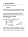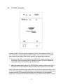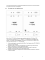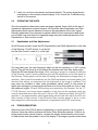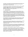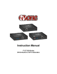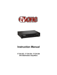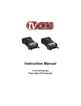
1
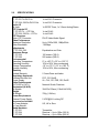
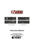
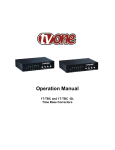
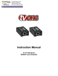
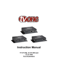
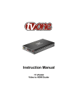
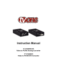
Instruction Manual
1T-CT-520 Series
DVI-D+Audio to CAT.5 Extenders
Table of Contents
1.0
Introduction
2
2.0
Specifications
4
3.0
Checking Package Contents
5
4.0
Connecting The Hardware
5
5.0
Operating The Unit
8
6.0
Troubleshooting
8
7.0
Limited Warranty
9
8.0
Regulatory Compliance
10
9.0
Contact Information
10
1.0
INTRODUCTION
Thanks for purchasing this Cat.5 Extender Product from TV One. The 1T-CT-520 Series
product is a system for transmission of DVI-D video plus either S/PDIF or analog stereo
signals over cables normally used for Ethernet transmission. Video resolutions up to
1920x1200 and 1080p can be realized over Cat.5/5E or Cat.6 cable at great distances.
The 1T-CT-521 Transmitter used in conjunction with the 1T-CT-524 Receiver can
achieve distances up to 100 meters (325 feet), while use of the 1T-CT-528 Receiver
can support distances up to 250 meters (800 feet). Both Receivers provide Gain and
Equalization adjustments resulting in excellent picture quality. The unique TV One-task
locking power connectors are used to enhance overall system security.
Our professional video conversion products have been serving the industry for over
twenty years. TV One offers a full line of high quality Seamless Switchers, Video
Scalers, Up/Down/Cross Converters, Analog-Digital Converters (SD/HD-SDI, HDMI,
DVI), Format Converters, Standards Converters, TBC/Frame Synchronizers, Matrix
Routing Switchers, Signal Distribution Amplifiers and Cat.5 Transmission Systems.
1.1
Liability Statement
Every effort has been made to ensure that this product is free of errors. TV One cannot
be held liable for the use of this hardware or any direct or indirect consequential
damages arising from its use. It is the responsibility of the user of the hardware to check
that it is suitable for his/her requirements and that it is installed correctly. All rights
reserved. No parts of this manual may be reproduced or transmitted by any form or
means electronic or mechanical, including photocopying, recording or by any
information storage or retrieval system without the written consent of the publisher.
TV One reserves the right to revise any of its hardware and software following its policy
to modify and/or improve its products where necessary or desirable. This statement
does not affect the legal rights of the user in any way.
All third party trademarks and copyrights are recognized. The TV One logo, TV Onetask and CORIO are the registered Trademarks of TV One. All other trademarks are the
property of their respective holders.
2
1.2
Features
The 1T-CT-520 Series DVI-D+Audio to CAT.5 Extender Systems have many features
that enable them to perform in a superior manner. Among those features you will find:
•
•
•
•
•
•
•
•
•
1.2
•
•
•
•
•
1.3
Resolutions to 1920x1200, 1080p @ 50/60Hz
Long Transmission Distance
1T-CT-524 provides up to 100 meters (325 feet)
1T-CT-528 provides up to 250 meters (800 feet)
Includes either S/PDIF or Stereo Audio
Built in EDID at Transmitter
Gain and EQ Adjustments
Normal operation requires 1x Cat.5, 5E or 6 Cable
Locking power supply for security
1T-CT-521 Transmitter Features
Compliant with DVI 1.0 specifications
EDID Capability
Supports CAT-5/CAT-5E/CAT-6 cables of variable lengths
Supports high definition input up to 1080P, output resolution follows input
Data Stream includes either S/PDIF or Stereo audio
1T-CT-524 and 1T-CT-528 Receiver Features
• Compliant with DVI 1.0 specifications
• Supports CAT-5/CAT-5E/CAT-6 cables of variable lengths
• Supports High Definition input up to 1080P, output resolution follows input
• 1T-CT-524 extends signal path to 100 Meters (325 Feet)
• 1T-CT-528 extends signal path to 250 Meters (800 Feet)
• Integrated Gain and Equalization Controls provided for both models
• Data Stream includes S/PDIF or Stereo audio
3
2.0
SPECIFICATIONS
Video I/O
1T-CT-521 Tx-DVI-D In
1T-CT-524, 528 Rx-DVI-D Out
Audio I/O
All Units
UTP Outputs I/O
1T-CT-521 Tx – UTP Out
1T-CT-524, 528 Rx – UTP In
UTP Structure
Video UTP Connector
Video Performance
Maximum Resolution
Video Bandwidth
Adjustments
1T-CT-524, 528
Maximum Range
1T-CT-524
1T-CT-528
Environmental
Operating Temperature
Operating Humidity
Storage Temperature
Storage Humidity
Warranty
Limited Warranty
Regulatory Approvals
Encoder/Decoder Unit
Power Supply
Cable Requirements
CAT.5/5E or CAT 6
Mechanical (H-W-D)
All Models
Weight
All Models
Power Requirement
External Power Supply
Accessories Included
1x Power Adapter
1x User Manual
Model Numbers
1T-CT-521
1T-CT-524
1T-CT-528
1x via DVI-I Connector
1x via DVI-I Connector
1x S/PDIF Coax, 1x 3.5mm Analog Stereo
1x via RJ-45
1x via RJ-45
DVI-D Video/Audio Signal
Up to 1920x1200, 1080p/60Hz
1.65Gbps
Equalization and Gain
100 meters (325 ft)
250 meters (800 ft)
0° to +50° C (+32° to +122° F)
10% to 90%, Non-condensing
-10° to +70° C (12° to +158° F)
10% to 90%, Non-condensing
2 Years Parts and Labor
FCC, CE, RoHS
UL, CUL, CE, PSE, GS, RoHS
Network Grade, Premium
30x123x125mm(1.18x4.84x”4.92)
700g (1.54 lbs)
5 VDC@2A, Locking DC
US, UK or Euro
Transmitter
Receiver – Up to 100m (325 ft)
Receiver – Up to 250m (800 ft)
4
3.0
CHECKING PACKAGE CONTENTS
Before attempting to use this unit, please check the packaging and make certain the
following items are contained in the shipping carton:
•
•
•
1x Transmitter or Receiver unit
1x Power Adapter
1x Operations Manual
Note: Please retain the original packing material should the need ever arise to return
the unit. If you find any items are missing, contact your reseller or TV One immediately.
Have the Model and Serial Number and Invoice available for reference when you call.
4.0
CONNECTING THE HARDWARE
Please study the panel drawings below and become familiar with the signal input,
outputs, power requirements/inputs plus any controls present. Note: The resolution
capability of the remotely located display devices must be capable of displaying the
output of the source device. Before connecting the CAT.5 extender system, verify that
the display device on the receiving end can support the output resolution and signal
format by connecting it directly to the source device.
4.1
Cat.5/5E/6 Cable Notes
Pins and pairing. Make sure the CAT5/5E/6 cable pin assignments are standard. The
correct pairing is straight through, pin-to-pin, with pairing as follows.
Twist density. UTP cable pairs have different twist densities (twist pitches). There are
two pairs with high density twist and two pairs with low density. Colors vary by
manufacturer. Twist densities can be seen by stripping off about 10 cm (4’) of insulation
and visually inspecting. Pairs 1-2 and 7-8 should be assigned to high density twists.
Failure to assign correct twist densities can result in image jitter. The ABCD picture
shows typical UTP cable, with pairs A and C showing a high pitch twist (assigned to pin
pairs 1-2 & 7- 8), and B and D with low pitch twist (assigned to pin pairs 3-6 & 4-5).
5
4.2
1T-CT-521 Transmitter
Connect the DVI-D source device’s output to the DVI-I IN connector of the 1T-CT521 Transmitter, using the appropriate DVI cable. Then connect either an S/PDIF
audio signal or an analog Stereo audio signal to the appropriate connector.
1. Connect a Cat.5/5E or Cat.6 cable to the VIDEO UTP output connector of the
Transmitter. Defer connecting the AC adapter until the Cat.5/Cat.6 cables are
connected to both the Transmitter and the Receiver.
2. Select the proper Audio type on the S/PDIF/Stereo switch located on the side of
the same end of the transmitter where the audio input connectors are located.
Note: Other than the audio select switch, there are no user controls provided on the
1T-CT-521 Transmitter. It’s important that you verify that the DVI-D source functions
properly with the DVI-D display device before you attempt to use the extender
system by connecting the two devices directly using a fully functional DVI-D. Failure
6
to do this would introduce an unwanted variable that will have to be resolved should
the system not function as expected.
4.2
1T-CT-524 and 1T-CT-528 Receivers
Note: If the CAT.5/Cat.6 cables runs are equal to or less than 100 Meters (325
Feet), you can use either the 1T-CT-524 or 1T-CT-528 Receiver to complete the
system. If the cable runs are between 100 Meters (325 Feet) and 250 Meters (800
Feet), you must use the 1T-CT-528 Receiver.
1. At the remote location, connect the Cat.5/5E or Cat.6 cable to the UTP VIDEO IN
connector of the Receiver.
2. Connect the DVI-I connector of the Receiver to the DVI-D input of the remote
display or other device, using the appropriate cable.
3. Connect the appropriate audio cable to the receiver and then to the audio
amplifier input or the audio input on the display device.
4. Connect the supplied AC adapters first to the Transmitter and Receiver and then
to the AC sockets.
7
5. Lastly, turn on the source device and remote display. The source signal should
now appear on the remotely located display. If not, consult the Troubleshooting
section of this manual.
5.0
OPERATING THE UNITS
Once the connections have been made and power applied, there is little in the way of
operational adjustments required however, all Receivers have Equalization and Gain
adjustments which may be adjusted to improve the appearance of the video signal.
Normally adjustment is not required on shorter cable runs but receivers located at the
end of cable runs near the limit of specified range may need small adjustments of the
Equalization or Gain controls or both.
5.1
Equalization and Gain Adjustments
On all Receiver models, locate the EQ (Equalization) and GAIN adjustments on the side
of the Receiver. The EQ control, is on the left
and the Gain Control is next to it, to the right.
On long cable runs, the high frequency detail can be lost resulting in a “soft” looking
picture. This will first show up in text where the characters will lose their sharp edges.
Adjust the EQ can sharpen the image. While viewing an image on a display connected
to the Receiver, insert a small screwdriver into the EQ adjustment on the side panel of
the Receiver. Rotate gently until the best EQ setting, as determined by image clarity, is
achieved. Next, insert the screwdriver into the GAIN adjustment, and rotate gently until
the best Gain setting, as determined by the brightness of the image is achieved. You
may notice an increase in video noise (sometimes called “snow”) in the picture at
higher gain settings so a compromise will have to be found if the cable run is at or near
the maximum length. EQ and GAIN settings are retained by the Receiver. On the 1TCT-528 Receiver, the longer range capability of this unit can be equalized using the
controls described above plus the use of the two DIP switches provided. Set the DIP
switches to the approximately cable length being utilized and then adjust the EQ and
Gain controls for best picture. If the EQ and/or Gain controls appear to be at or near
their range limit, select another combination of switches from the DIP switch array.
6.0
TROUBLESHOOTING
Other than faulty Cat.5/Cat.6 cables or attempting to use the product over too great a
distance, there are seldom problems with these Video Extender products. If there is no
image present at the remote location, connect the display device directly to the source
to make certain that the problem is not in the display. If an image is present under those
8
circumstances, make certain the transmitter and receiver(s) are receiving power. Next
make certain your Cat.5/5E/6 cable is defect free and the RJ-45 connectors are
securely attached to the cable at both ends.
After trying the above suggestions should the problem still persist, contact your dealer
for additional suggestions before contacting TV One. Should the dealer’s technical
personnel be unable to assist you, contact TV One via our support website:
http://tvone.crmdesk.com. Create a technical support request on the site and our
support team will respond within a short period of time.
7.0
LIMITED WARRANTY
LIMITED WARRANTY – With the exceptions noted in the next paragraph, TV One
warrants the original purchaser that the equipment it manufactures or sells will be free
from defects in materials and workmanship for a period of two years from the date of
purchase. Should this product, in TV One’s opinion, prove defective within this warranty
period, TV One, at its option, will repair or replace this product without charge. Any
defective parts replaced become the property of TV One. This warranty does not apply
to those products which have been damaged due to accident, unauthorized alterations,
improper repair, modifications, inadequate maintenance and care, or use in any manner
for which the product was not originally intended.
Items integrated into TV One products that are made by other manufacturers, notably
computer hard drives and liquid crystal display panels, are limited to the term of the
warranty offered by the respective manufacturers. Such specific warranties are
available upon request to TV One.
If repairs are necessary under this warranty policy, the original purchaser must obtain a
Return Authorization Number from TV One and return the product to a location
designated by TV One, freight prepaid. After repairs are complete, the product will be
returned, freight prepaid.
LIMITATIONS - All products sold are "as is" and the above Limited Warranty is in lieu of
all other warranties for this product, expressed or implied, and is strictly limited to two
years from the date of purchase. TV One assumes no liability to distributors, resellers or
end-users or any third parties for any loss of use, revenue or profit.
TV One makes no other representation of warranty as to fitness for the purpose or
merchantability or otherwise in respect of any of the products sold. The liability of TV
One with respect to any defective products will be limited to the repair or replacement of
such products. In no event shall TV One be responsible or liable for any damage
arising from the use of such defective products whether such damages be direct,
indirect, consequential or otherwise, and whether such damages are incurred by the
reseller, end-user or any third party.
9
8.0
REGULATORY COMPLIANCE
The 1T-CT-520 Series DVI-D+Audio Extender products have been tested for
compliance with appropriate FCC and CE rules and regulations. The Power
Adaptor/Supply has been tested for compliance with appropriate UL, CUL, CE, PSE,
GS Rules, Regulations and/or Guidelines. This Product and Power Adapter is RoHS
Compliant.
9.0
CONTACT INFORMATION
Should you have questions or require assistance with this product in areas not covered
by this manual, please contact TV One at the appropriate location shown below.
TV One USA
2791 Circleport Drive
Erlanger, KY 41018
USA
Tel 859-282-7303
Fax 859-282-8225
[email protected]
www.tvone.com
TV One Europe
Continental Approach
Westwood Industrial Estate
Margate, Kent CT9 4JG, UK
Tel +44 (0)1843 873311
Fax +44 (0)1843 873312
[email protected]
www.tvone.eu
TV One Latin America
6991 NW 82 Avenue #8
Miami, FL 33166
USA
Tel 305-396-6275
Fax 305-418-9306
[email protected]
www.tvonela.com
TV One Mercosur
Honduras 5849, 2nd Floor, Office C
(C1414BNI) Capital Federal
Buenos Aires, Argentina
Tel +54 11 4771-5570
Fax +54 11 4771-5570
[email protected]
www.tvonela.com
TV One Asia
11F, NO.28, Sec. 2
San-Min Rd, Panchiao City
Taipei Hsien 220
Taiwan R.O.C.
Tel +886 2 8951-0674
Fax +886 2 8951-0675
[email protected]
www.tvoneasia.com
TV One China
Room 1007, Golden Peach Building
No. 1900 Shangcheng Road
Pudong, Shanghai
China 200120
Tel +86 21 5830-2960
Fax +86 21 5851-7949
[email protected]
www.tvonechina.com
End of Manual
10