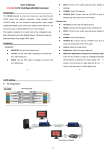
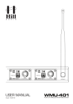
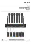
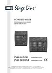
1
SOUND SERVICES 43 ALBANY ROAD GU51 3PU FLEET 01252 620227 www.soundservices.co.uk PMX-162 - Powered Mixer Powered mixer, 160 WRMS/240 WMAX/4 Ohm • • • • • • • • • • Audio mixer and audio amplifier built into a wooden housing with black plastic coating 4 mono input channels, each with gain control, 2-way tone control and effect control 2 stereo input channels, each with gain control, 2-way tone control and effect control Integrated USB MP3 player with LCD Adjustable digital reverb Adjustable effect way Tape record and CD/tape play connections 15 V phantom power, can be switched centrally 5-band graphic equalizer LED level display MONACOR UK LTD - U8, PLOVER CLOSE, NEWPORT PAGNELL, MILTON KEYNES, MK16 9PS - MONACOR.CO.UK SOUND SERVICES 43 ALBANY ROAD GU51 3PU FLEET 01252 620227 www.soundservices.co.uk Technical data RMS output power : 160 WRMS/4 Ohm110 WRMS/8 Ohm Frequency range Input sensitivity : 20-20,000 Hz : 1.5 mV (mic)50 mV (line)240 mV (tape)1 V (effect return) Outputs : 540 mV (tape rec.)1 V (effect send) S/N ratio THD Equalizer Bass Treble Graphic equalizer Power supply Admiss. ambient temp. Dimensions Weight : : : : : : : : : : 77 dB 0.1 % ±15 dB/60 Hz ±15 dB/15 kHz ±12 dB, 60/250/800 Hz/2/8 kHz 230 V~/50 Hz/370 VA 0-40 °C 440x200x305 mm 10.6 kg MONACOR UK LTD - U8, PLOVER CLOSE, NEWPORT PAGNELL, MILTON KEYNES, MK16 9PS - MONACOR.CO.UK SOUND SERVICES 43 ALBANY ROAD GU51 3PU FLEET 01252 620227 www.soundservices.co.uk PAB-110MK2 - PA Speaker Cabinet The 100 series provides PA speaker systems of high power capability with a nice sound for PA and DJ applications and is suitable for medium-sized to large function rooms. The timeless plastic cabinets are also very robust and have extensively been tested in practical operation. DJ and power speaker system, 400 WMAX, 8 Ohm • • • • • • • • • Full range system of high power capability and of high efficiency Robust plastic cabinet 25 cm (10") bass speaker with diecast aluminium basket 25 mm (1", 34 mm voice coil) horn tweeter Bass-reflex system Multi-purpose positioning and installation options M8 threaded inserts (2 x top, 1 x bottom) 2 x speaker terminal, in/out Stand sleeve and carrying handle Due to the centre of gravity inside these very compact cabinets, stands with legs of a sufficient size have to be selected for the PAK-110MK2 and the PAB-110MK2, e.g. PAST-164/SW. KEYBOARDS 01/2012 "For anyone who likes the combination of a passive PA speaker system and a separate power amplifier for live performances, the PAB-110MK2 from IMG Stage Line is going to be a powerful and above all a reliable ally for providing a great sound. ... a useful and easy-to-use tool ... provides a clear and above all a pleasantly defined live sound which can be classified as premium in this price class."+ robust workmanship+ distortion-free also at maximum levels MONACOR UK LTD - U8, PLOVER CLOSE, NEWPORT PAGNELL, MILTON KEYNES, MK16 9PS - MONACOR.CO.UK SOUND SERVICES 43 ALBANY ROAD GU51 3PU FLEET 01252 620227 www.soundservices.co.uk Technical data Bass-midrange speaker Power capabilities Music power Power rating General information Impedance Frequency range SPL (1 W/1 m) Max. rated SPL Admiss. ambient temp. Dimensions (WxHxD) Weight Connections : : : : : : : : : : : : : 25 cm (10") 400 WMAX 200 WRMS 8 Ohm 59-20,000 Hz 97 dB 120 dB 0-40 °C 360x500x260 mm 11.1 kg 2 x SPEAKER par. in/out MONACOR UK LTD - U8, PLOVER CLOSE, NEWPORT PAGNELL, MILTON KEYNES, MK16 9PS - MONACOR.CO.UK SOUND SERVICES 43 ALBANY ROAD GU51 3PU FLEET 01252 620227 www.soundservices.co.uk PAB-112MK2 - PA Speaker Cabinet The 100 series provides PA speaker systems of high power capability with a nice sound for PA and DJ applications and is suitable for medium-sized to large function rooms. The timeless plastic cabinets are also very robust and have extensively been tested in practical operation. DJ and power speaker system, 500 WMAX, 8 Ohm • • • • • • • • • Full range system of high power capability and of high efficiency Robust plastic cabinet 30 cm (12") bass speaker with diecast aluminium basket 25 mm (1", 34 mm voice coil) horn tweeter Bass-reflex system Multi-purpose positioning and installation options M8 threaded inserts (2 x top, 1 x bottom) 2 x speaker terminal, in/out Stand sleeve and carrying handle Beat 06/2012 "The PAB-112MK2 is a really good entry-level unit for getting hooked on DJing. It provides a powerful and well-balanced sound and is of a neat workmanship ... the unit is highly enjoyable. Features a very good price-performance ratio." + neat workmanship + clear sound + lightweight tastenwelt 02/2012 "The plastic housings are of neat workmanship ... the MMX-842USB is a good choice ... the STA-225 features all standard protective circuits, even a clip limiter can be switched on additionally. A display shows useful information on the operation. The system tested provided a really appealing sound: a nice deep bass reproduction and a clear midrange of the 12" speakers and a full and clear reproduction of the high frequencies, too. With the support of a subwoofer, the volume which can be achieved is already sufficient to MONACOR UK LTD - U8, PLOVER CLOSE, NEWPORT PAGNELL, MILTON KEYNES, MK16 9PS - MONACOR.CO.UK SOUND SERVICES 43 ALBANY ROAD GU51 3PU FLEET 01252 620227 www.soundservices.co.uk show a great performance at smaller to medium-sized events. Neither the active bass speaker nor the passive top parts provide an unpleasant or even overstrained sound." (PA setup of PAB-112MK2, PSUB-115AK, STA-225, MMX-842USB) MONACOR UK LTD - U8, PLOVER CLOSE, NEWPORT PAGNELL, MILTON KEYNES, MK16 9PS - MONACOR.CO.UK SOUND SERVICES 43 ALBANY ROAD GU51 3PU FLEET 01252 620227 www.soundservices.co.uk Technical data Bass-midrange speaker Power capabilities Music power Power rating General information Impedance Frequency range SPL (1 W/1 m) Max. rated SPL Admiss. ambient temp. Dimensions (WxHxD) Weight Connections : : : : : : : : : : : : : 30 cm (12") 500 WMAX 250 WRMS 8 Ohm 55-20,000 Hz 98 dB 122 dB 0-40 °C 430x580x310 mm 16.1 kg 2 x SPEAKER par. in/out MONACOR UK LTD - U8, PLOVER CLOSE, NEWPORT PAGNELL, MILTON KEYNES, MK16 9PS - MONACOR.CO.UK QU4 Quad UHF Wireless System Item ref: 171.840, 171.841, 171.842 User Manual Version 1.1 171.840, 171.841, 171.842 User Manual Introduction Thank you for choosing the Chord QU4 wireless system. This professional wireless set provides 4 high quality microphones with UHF radio system for freedom of movement without loss of audio quality. Please read this manual before using this item in order to avoid damage and to get the best performance from your purchase. Package Contents UHF quad wireless receiver 19” rack ears 2 x antennae Mains power adapter 6.3mm mono jack lead 8 x 1.5V AA battery QU4-H version – 4 x handheld transmitters QU4-N version – 4 x neckband microphones + 4 x beltpack transmitters QU4-C version – 2 x handheld transmitters + 2 x neckband microphones + 2 x beltpack transmitters If you find any accessory is missing or the product has arrived with any problems, please contact your retailer. This product contains no user-serviceable parts so make no attempt to try to fix or modify this item yourself as this will invalidate the warranty. We recommend you keep the original package and proof of purchase for any possible replacement or returned demand. Warning To prevent the risk of fire or electric shock, do not expose any of the components to rain or moisture. If liquids are spilled on any component, stop using immediately, allow unit to dry out and have checked by qualified personnel before further use. Avoid impact or heavy vibration to any of the components, dropping the microphone can cause capsule failure. No user serviceable parts inside transmitter or receiver - refer servicing to qualified service personnel. Safety Ensure that the correct adapter is used with adequate current rating and that the mains voltage is as stated on the adapter Avoid ingress of water or particles into the transmitters or receiver Use alkaline or NiMH batteries in the transmitters and remove if unused for long periods Observe the correct polarity when replacing batteries Placement Keep all components out of direct sunlight and away from heat sources Do not place heavy objects on top of the receiver or transmitters If rack-mounting, use the rack-ears provided and do not place heavy equipment above the receiver Take care to keep antennae from sticking out where they may get damaged Keep the transmitters and receiver away from damp or dusty environments Cleaning Use a soft cloth with a neutral detergent to clean the body of the handheld transmitter and receiver. Lightly damp sterile wipes may be used on the microphone grilles for hygiene purposes To avoid damage, do not use solvents to clean the components 171.840, 171.841, 171.842 User Manual Control Layout 1. 2. 3. 4. 5. 6. 7. 8. 9. 10. 11. 12. Antenna connection (TNC) Power switch Power indicator RF indicator AF indicator VOLUME control On indicator Off – Mute – On switch Battery compartment Gain control Antenna 3.5mm threaded jack socket Setting Up Insert the supplied AA batteries into the handheld or beltpack transmitters by carefully unscrewing the base or flipping forward the front cover to reveal the battery compartment inside the transmitter body, connect the batteries (ensure + and - are the correct way round for each cell) and carefully replace the cover. Connect neckband microphones to the relative beltpack transmitters by connecting and screwing in the 3.5mm jack plug fully. Screw on the front-mounted TNC antennae and position the receiver within the best available line of sight to the transmitter(s). Connect the DC jack of the supplied power adapter to the receiver and the plug top to the mains outlet. Turn microphone level(s) down on the receiver. A choice of mixed output of all 4 microphones on 6.3mm jack or individual balanced XLR outputs is available on the rear panel of the receiver. Connect jack or XLR (optional) leads to the relative output connector(s), turn down the volume of any equipment (mixer, amplifier etc.) that the signal will be fed into and then connect the jack or XLRs to the equipment. Warning! - take care not to point microphones towards speakers – this can cause damaging feedback (loud whistle or howling noise) – try to point microphones away from the speaker cabinets. 171.840, 171.841, 171.842 User Manual Operation Switch on power to the receiver unit and check that the red power LED is lit on each channel (if not, turn the VOLUME rotary control just past the zero point). Move the switch on the first handheld or beltpack transmitter to the first notch (MUTE) – the LED should light momentarily. Move on another notch (Fully ON) and gradually increase the microphone level on the receiver, then increase the volume on the mixer or amplifier until the sound from each microphone can be heard through the equipment. Repeat for the other 3 microphones. (Note: if output is low from neckband microphones, it may be necessary to adjust Gain control inside the beltpack unit). During use, it may be useful for the reception of the microphone to be muted for a short period of time (e.g. to avoid feedback when walking across the front of a speaker or avoid handling noise when placing the microphone down momentarily or adjusting a neckband microphone). In these circumstances, it may be better to move the transmitter switch to the “MUTE” position, which maintains the radio frequency carrier signal but mutes the microphone input. When this switch is moved back to the “ON” position, the sound will be immediately restored without waiting for the radio signal to be reinstated. If the wireless system is not to be used for more than a few seconds, it is preferable to slide the transmitter switch to the “OFF” position, which mutes and deactivates the radio signal and powers down the transmitter. Be sure to turn down the volume of the mixer or amplifier and then switch off the receiver. Unplug signal leads from the receiver and mixer or amplifier when moving or packing away. If the system is not to be used for long periods of time, remove the batteries from the transmitters and unplug the power adapter from the receiver and the mains outlet. Folding away or removing the antennae can also help avoid damage when the system is not in use. Power supply Batteries Carrier frequency Stability S/N ratio THD Image rejection Range Output impedance Output level Connectors Dimensions - handheld transmitter Weight - handheld transmitter Dimensions - beltpack transmitter Weight - beltpack transmitter Dimensions - receiver Weight - receiver Specifications 12 - 18Vdc 800mA adaptor (supplied) 8 x AA (included) 863.42, 864.99, 864.30 and 863.01MHz 10PPM >105dB <0.5% @ 1KHz 85dB typical 60m (max) 2.2k ohms Balanced: 0-400mv, unbalanced: 0-200mv DC in, 4 x XLRM, 6.3mm jack 243 x 48mmØ 238g (no battery) 205 x 68 x 25mm 76g (no battery) 483 x 44 x 225mm 3.8kg 171.840, 171.841, 171.842 User Manual Troubleshooting “POWER” LED does not Ensure power adapter is connected to mains and working properly light on receiver Ensure receiver is switched on Ensure transmitter is switched on “POWER” LED is lit but Check that transmitter is not out of reception range no “RF” or “AF” LEDs Check that transmitter batteries are good / charged Check that transmitter switch is not in “MUTE” position “POWER” and “RF” LEDs are lit but no Ensure transmitter has good / charged batteries “AF” and no sound Ensure there is no other nearby transmitter with the same frequency Make sure receiver is properly connected to mixer / amplifier All LEDs lit but no sound from mic Ensure that receiver and amplifier/mixer channel volumes are turned up Turn down VOLUME on receiver Reduce Gain on beltpack transmitter Microphone output is very loud or distorted Reduce Gain on mixer / amplifier Ensure that XLR output is not fed to a Line input Turn up VOLUME on receiver Increase Gain on beltpack transmitter Microphone output is Increase Gain on mixer / amplifier very low Ensure that Jack output is not fed to a Mic input Check transmitter batteries 1622 DISPOSAL: Please dispose of the unserviceable device according to the current statutory requirement Errors and omissions excepted. Copyright© 2012. AVSL Group Ltd. 171.840, 171.841, 171.842 User Manual