1
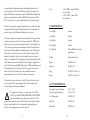
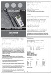
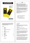
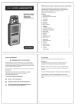
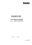
Metrohm
Martindale Electric
Metrohm House
Penfold Trading Estate
Imperial Way
Watford WD24 4YY
T: 01923 441717
F: 01923 446900
Email: [email protected]
web: www.martindale-electric.co.uk
E3511
HIGH VOLTAGE INSULATION TESTER
INSTRUCTION MANUAL
LITE3511
ISSUE 9 01/07
®
Martindale Electric
The purchaser agrees to assume all liability for any damages and bodily
injury which may result from the use or misuse of the product by the
purchaser, his employees, or others, and the remedies provided for in this
warranty are expressly in lieu of any other liability Martindale Electric
Company Ltd may have, including incidental or consequential damages.
Martindale Electric Company Ltd reserve the right to discontinue models
at any time, or change specifications, price or design, without notice and
without incurring any obligation.
TABLE OF CONTENTS
PAGE
1. SAFETY RULES
2-3
2. DESCRIPTION
2.1 GENERAL
3-4
2.2 FRONT PANEL LAYOUT
5
2.3 TYPICAL TERMINAL VOLTAGE CHARACTERISTICS
5
3. PREPARATION FOR USE
6
4. INSTRUCTIONS FOR USE
4.1 PRELIMINARY CHECKS
7
4.2 TESTING INSULATION TO EARTH
7-8
4.3 TESTING INSULATION BETWEEN CONDUCTORS
8
4.4 GUARD TERMINAL
8
4.5 AC INTERFERENCE
9
4.6 INTERNAL POWER SUPPLY
9
4.7 ‘BAT’ INDICATION
9-10
4.8 INPUT LIMITS
10
5. APPLICATIONS
10-11
6. TECHNICAL SPECIFICATION
6.1 ELECTRICAL
11-13
6.2 MECHANICAL
13
6.3 ENVIRONMENTAL
13
7. SPARES AND ACCESSORIES
14
8. LIMITED WARRANTY
15
!
1. SAFETY RULES
The E3511 has been designed with safety in mind. However, no design
can completely protect against incorrect use. Electrical circuits can be
dangerous and even lethal through lack of caution or poor safety
practices. The following rules will minimise the danger:1.1
Read the Instruction Manual carefully and completely before using
this instrument. Fully understand the instructions before using this
tester. Follow the instructions in the Manual for every test. Take all
the precautions recommended. Never exceed the limits of this
tester.
1.2 The circuit to be tested must be de-energised and isolated before
connections are made for an insulation test.
1.3 Do not touch the circuit being tested during an insulation test.
1.4 After an insulation test, capacitive circuits must be discharged
before disconnecting the test leads.
1.5 Do not use test leads, probes or crocodile clips that are dirty,
damaged or have broken or cracked insulation. Such accessories
should be immediately removed and repaired.
1.6 Always disconnect the supply lead to de-energise the tester before
replacing the internal fuse, and don’t press the TEST button.
Always replace the fuse with the type specified and ensure that it is
correctly fitted.
1.7 Never latch the TEST button on unless it is absolutely necessary.
Be extremely careful not to cause a hazard if this is done.
1.8 Always connect the HV leads to the high (H) and low (L) sockets
before switching the tester on.
1.9 Do not touch any part of the test leads or croc clips when carrying
out insulation tests at voltages greater than 1000V. Always keep
your hands behind the hand guards on the probes and crocodile
clips.
1.10 This instrument must not be used in wet conditions.
8. LIMITED WARRANTY
Martindale Electric Company Ltd warrant instruments and test
equipment manufactured by them to be free from defective material
or factory workmanship and agree to repair or replace such products
which, under normal use and service, disclose the defect to be the
fault of our manufacturing, with no charge for parts and service. If
we are unable to repair or replace the product, we will make a refund
of the purchase price. Consult the Instruction Manual for instructions
regarding the proper use and servicing of instruments and test
equipment. Our obligation under this warranty is limited to repairing,
replacing or making refund on any instrument or test equipment
which proves to be defective within 24 months from the date of
original purchase. Proof of purchase date required.
This warranty does not apply to any of our products which have been
repaired or altered by unauthorised persons in any way so as, in our
sole judgement, to injure their stability or reliability, or which have
been subject to misuse, abuse, misapplication, negligence or accident,
or which have had the serial numbers altered, defaced or removed.
Accessories, not of our manufacture, used with this product are not
covered by this warranty.
To register a claim under the provisions of this warranty, return the
instrument or test equipment to Martindale Electric Company Ltd,
Metrohm House, Penfold Trading Estate, Imperial Way, Watford
WD24 4YY. Upon our inspection of the product we will advise you
as to the disposition of your claim.
ALL WARRANTIES IMPLIED BY LAW ARE HEREBY LIMITED TO
A PERIOD OF TWENTY FOUR MONTHS, AND THE PROVISIONS
OF THE WARRANTY ARE EXPRESSLY IN LIEU OF ANY OTHER
WARRANTIES EXPRESSED OR IMPLIED.
NOTE: This instrument should only be used by a competent, suitably
trained person.
-2-
-15-
Explanation of Symbols Used
7. SPARES AND ACCESSORIES
Test Lead Kit (2m)
METDFK 0075A
Test Lead Kit (10m)
METDFK 0075C
Caution, risk of electric shock
!
Caution, refer to Instruction Manual
Terminal of measuring circuit connected to accessible
conductive parts (see IEC 1010, Part 5.1.6(c)).
2.DESCRIPTION
2.1 GENERAL
The E3511 is a portable, high voltage, insulation tester that can be
operated from its internal, rechargeable batteries or from the external AC
supply. Four test voltages, 0.5kV, 1.0kV, 2.5kV and 5.0kV are available
with the same measurement resistance range of 100kΩ to100GΩ. The
tester can also function as a volt metre with a range of 1000V AC or DC.
This instrument has two principle circuits; a high voltage DC converter
and a log ratio amplifier. The high voltage DC convertor generates the
test voltage selected at the measurement terminals.The log ratio amplifier
compares the current flowing through the measurement terminals with the
voltage across them. The output of this amplifier is, therefore, the
logarithm of the insulation resistance across the measurement terminals
and this is displayed on the meter.
When the TEST push button is not pressed, the tester operates as a volt
meter. This gives an indication that the equipment being tested is deenergised before an insulation test and monitors the discharge of
capacitive circuits when the TEST push button is released. The resistance
associated with the volt meter acts as a discharge circuit so that, when the
TEST push button is released after an insulation test, any capacitive
circuit is automatically discharged.
-14-
-3-
An integral battery charger unit recharges the internal batteries when AC
power is supplied to the tester. The indicator, adjacent to the mains socket,
lights when the batteries are being recharged. The BAT indicator lights if the
batteries are in a charged state when the TEST push button is pressed. The
E3511 can continue to be operated whilst the batteries are being recharged.
Fuses:
The tester is packaged in a rugged, moulded plastic case with an integral
carrying handle. The hinged, detachable lid protects the front panel and
provides storage for the Instruction Manual and accessories.
6.2 MECHANICAL
The controls, displays and terminals are mounted on the front panel. A four
position rotary switch selects the test voltage required. The ‘TEST’ pushbutton is pressed to perform an insulation test and it can be latched into its
‘ON’ position by pressing down and turning clockwise. The high (H) and
low (L) measurement terminals are latching coaxial sockets that enable the
test leads to be screened to reduce errors due to leakage. The guard (G)
terminal is a shrouded, safety socket and it enables errors due to surface
leakage to be eliminated. The mains input socket has an integral fuse holder
and the indicator adjacent to it lights when an AC supply is supplied to the
tester. The indicator marked BAT lights when the TEST push-button pressed
if the internal battery is in a charged state. The moving coil meter has a
white scale plate with a black upper scale for insulation resistance
measurements and a red lower scale for voltage measurements.
The standard accessory kit consists of the HV, screened test leads with
probes, a guard lead, a mains supply lead for battery charging, three
crocodile clips and an Instruction Manual.
The supplied test leads and croc clips are rated at CAT III
1000V. They should NOT BE HAND HELD OR TOUCHED
when using insulation test voltages greater than 1000V. The
physical sizes required to provide full levels of safety isolation at higher
voltages would render the test leads unusable in many applications
therefore safe working practices must be observed.
-4-
0.2A, F, HBC, ceramic, DIN fuse
on power inlet;
0.63A, T, HBC, ceramic, DIN
fuse on battery
Case Length:
330mm
Case Width:
263mm
Case Height:
144mm
Scale Length:
133mm
Case Material:
Yellow ABS, black and clear
polycarbonate
Weight:
4.2kg (with batteries)
Bump:
To IEC68-2-29
Vibration:
To IEC68-2-6
Drop:
To IEC1010, Clause 8.4
Impact:
To IEC1010, Clause 8.2
6.3 ENVIRONMENTAL
Operating Temperature Range:
Storage Temperature Range:
15ºC to +55ºC
-25ºC to +65ºC
Cold Temperature:
To IEC68-2-1
Dry Heat:
To IEC68-2-2
Damp Heat:
To IEC68-2-3
-13-
Short Circuit Current:
1.2mA nominal
Ripple Voltage:
<10V peak to peak (R<10MΩ)
Hum Rejection:
2mA RMS on 5kV range
Capacitor Charging Time:
15 seconds nominal to charge a
2μF capacitor to 5kV
Capacitor Discharge Time:
2 seconds nominal to discharge a
2μF capacitor from 5kV to 50V
Voltmeter Range:
1000 volts AC or DC
Voltmeter Range Accuracy:
±1.5% of scale length
Maximum Voltage on
Measurement Terminals:
2.2 FRONT PANEL LAYOUT
2.3 TYPICAL TERMINAL VOLTAGE CHARACTERISTICS
1kV across H and L terminals;
1kV across H and guard;
250V across L and guard
Internal Battery:
12V, 1.25AH, NiCad
Pack Battery Low Voltage:
10.5 volts nominal
Maximum Battery Consumption:
400mA
Battery Life:
2 - 8 hours typical
Internal Power Supply/Charger:
240VAC, ±10%, 50/60Hz, 18VA
or 120VAC, ±10%
Protection:
Safety:
Over-voltage and over-current
protection on measurement
terminals;
VDR on power inlet socket;
GDT on L terminal
EMC:
Meets EN 50081-1
EN 50082-1
LVD:
Meets BS EN 61010
-12-
Fig. 2
-5-
(b)
PREPARATION FOR USE
This parameter is obtained by monitoring the insulation under
test for 60 seconds. The dielectric absorption ratio is then the
ratio of the insulation resistance reading at 60 seconds to that at
30 seconds. This technique provides conclusive results on the
quality of the insulation, which are independent of temperature
and equipment size. A ratio less than 1.25 is cause for
investigation and possible repair of the equipment tested. Current
flowing in the surface leakage path is diverted through the guard
terminal and is not included in the measurement. In this way, the
insulation measured is only the radial insulation value.
The Metrohm E3511 is delivered in a shipping container. When it is unpacked, it
should be checked for any visible signs of damage, and the preliminary checks
described in the operation instructions should be performed to ensure that it is
operating correctly. If there is any sign of damage or if the instrument does not
operate correctly, return it to the supplier.
This instrument can be powered from a power source of 240VAC, 50/60Hz or
120VAC, 50/60Hz. Check the power source available is compatible with the rated
supply voltage of the instrument.
This instrument can also be powered from its internal rechargeable battery. If this
battery is in a charged state, the lamp marked BAT should light when the TEST
button is pressed. If it does not light, the battery is discharged and testing should be
discontinued until the battery is recharged. This is done by connecting the tester to a
power source by its power supply cord and switching on the power source. The
lamp above the power socket should light to indicate that the battery is being
charged. The battery should be charged for 12 hours. If the instrument has not been
used for several months, then recharge its battery before putting it into operation. It
should be noted that any over-discharged battery may require several
charge/discharge cycles before it fully recovers. To avoid this problem, it can be
charged on a regular basis, e.g. monthly, to make the instrument serviceable. Note
that an instrument can be used for testing while it is being charged (see 4.6).
The battery should remain serviceable for at least 5 years if it is not over-discharged
or subjected to high temperatures for prolonged periods. Over-discharging can cause
the cells to lose their memory. Though this battery can operate from -40ºC to +60ºC,
it should be kept at +5ºC to +35ºC as its performance deteriorates out with this
temperature band. Never short circuit the battery as self-heating of the battery could
be dangerous. Always check with the battery manufacturer regarding their disposal.
It is recommended that the E3511 be calibrated every 2 years, and that it should be
carried out by the manufacturer or his appointed agent. If the tester develops a fault,
it should be returned to the manufacturer for repair. Dangerous voltages are
developed in certain parts of the instrument circuit and so it must be repaired by
qualified personnel who are aware of this danger.
-6-
Dielectric Absorption Ratio
(c)
Polarisation Index
The polarisation index test is a specialised application of the
dielectric absorption test with the insulation resistance reading
being taken at 1 and 10 minutes, rather than 30 and 60 seconds.
The polarisation index is the ratio of the reading at 10 minutes
to that at 1 minute. A ratio less than 2.0 is cause for
investigation.
6.TECHNICAL SPECIFICATION
6.1 ELECTRICAL
Insulation Resistance Range:
100kΩ to 100GΩ
Insulation Range Accuracy:
±1.5% of scale length
Insulation Range
Temperature Coefficient:
<0.04% of scale length/°C
Test Voltages:
500V, 1kV, 2.5kV, 5kV DC
Test Voltage Accuracy:
±5% at 10MΩ
Break Point Current:
0.5mA nominal
-11-
4.8 INPUT LIMITS
The maximum continuous voltage that can be applied across the
high and low terminals, across the high and guard terminals and
across the low and guard terminals are 1000, 1000 and 250 volts
respectively. These limits must never be exceeded.
5. APPLICATIONS
This tester is designed for use in dry conditions, pollution category
II. It should never be used in wet conditions. As an insulation tester,
it should only be used to test de-energised plant equipment and
components. As a voltage tester it is rated up to 1kV for installation
category III.
This tester is particularly suited for making insulation resistance
measurements on many electrical plant components, such as motors,
generators, transformers, switch gear, insulators, cables and wiring
installations. It can be used to perform the initial verification tests
and, thereafter, regular routine tests. If the results of such tests are
recorded, the degradation of the insulation with time can be
quantified and predicted, so allowing cost effective planned
maintenance to be organised. Due to its battery operation, it is
suitable for service and field applications.
There are various measurement techniques associated with
insulation testing that are useful in assessing the condition of the
insulation. Some of these techniques are described below:-
4. INSTRUCTIONS FOR USE
4.1 PRELIMINARY CHECKS
1.
Connect the HV test leads to the ‘H’ and ‘L’ sockets. Do not
press the ‘TEST’ button. The meter pointer should be at the ‘∞’
mark on the upper scale. It can be set to the required position
with the zero adjuster below the meter, using a small screwdriver.
2.
With the HV leads open-circuited, press the ‘TEST’ button. The
pointer should be very close to the ‘∞’ mark on the upper scale.
If it is not, there is a leakage path. Release the ‘TEST’ button and
check for the leakage path.
3.
Connect the clips on the HV test leads together to make a short
circuit. Press the ‘TEST’ button and check that the meter reads
zero on the upper scale. Release the ‘TEST ' button. If the
reading is not zero, check the HV test leads for a fault, i.e.
open circuit.
4.
During (3.) the ‘BAT’ indicates should light. If it does not,
recharge the battery.
4.2 TESTING INSULATION TO EARTH
1.
Perform the preliminary checks previously described.
2.
(a)
Step Voltage Method
In this method, a multi-voltage tester applies voltage in steps
to the insulation under test. Weak insulation is indicated by
lower resistance at higher voltage levels. This method is
useful in revealing ageing and physical damage in clean, dry
insulation.
-10-
3.
Connect the ‘L’ probe to a suitable earth point on the equipment
to be tested (frame of the equipment) and then connect the ‘H’
probe to a suitable voltage input point on the equipment to be
tested.
If a reading is obtained on the meter, DO NOT press the TEST
button. The equipment may be energised. Never attempt an
insulation test on energised equipment, as there could be a hazard
to the operator and the tester. Make sure that the equipment is
de-energised before proceeding with a test.
-7-
If the equipment is de-energised, the voltage reading could be due
to AC interference currents. Consult the section on AC
interference, 4.5, before proceeding.
4.
Select the required test voltage and press the ‘TEST’ button. The
‘BAT’ lamp should light. If it does not, connect the instrument to
an AC power socket to recharge whilst continuing the testing
(see 4.6)
5.
Read the value of insulation resistance directly from the upper
scale.
6.
Release the ‘TEST’ button and wait until the reading on the
voltage scale is less than 50 volts before disconnecting the test
leads.
4.5 AC INTERFERENCE
Insulation measurement can be affected by AC interference due to capacitive or
inductive coupling between the equipment being tested and live circuits. On the
5kV range, the maximum level of AC interference current that can be tolerated
is 2mA and at lower voltage settings it is proportionally less. When these
currents are transient or varying in amplitude, the readings will be unstable as
the input filter will not attenuate low frequencies. This problem will be most
pronounced with very high values of resistance on low voltage ranges.
It is possible to detect the presence of AC interference on the voltage scale, i.e.
when the ‘TEST’ button is released. A reading of 270 volts on this scale
corresponds to 2mA of interference current.
If AC interference is a problem, the best solution is to de-energise the live circuit
causing the problem where this is practical.
4.3 TESTING INSULATION BETWEEN CONDUCTORS
1.
Perform the preliminary checks previously described.
2.
Connect one test probe to each conductor.
3.
Proceed as before for steps (3.) to (6.).
4.4 GUARD TERMINAL
When performing an insulation test between the inner core of a cable and
its outer sheath, there are two insulation paths; a radial path through the
insulation and a surface leakage path across the insulation. These two
insulation paths are effectively in parallel, and it is possible to eliminate
the surface leakage path from the measurement. This is accomplished by
tightly wrapping a piece of bare wire round the insulation mid-way
between the inner core and outer sheath and connecting this wire to the
guard terminal.
-8-
4.6 INTERNAL POWER SUPPLY
This tester has an internal power supply which can charge the internal
rechargeable battery and power the tester at the same time. The power lead
provided connects the tester to the AC power socket. When power is supplied to
the tester, the lamp above the power inlet socket should light, indicating that the
internal battery is being charged. In this state, if the ‘TEST’ button is pressed,
the tester can take measurements while being powered by the AC power source.
This feature allows lengthy tests to be made with the tester supplied by an AC
power source, so conserving the battery. In addition, it allows the battery to be
recharged while testing is in progress.
4.7 ‘BAT’ INDICATION
The lamp above the ‘TEST’ button, marked BAT, should light when the ‘TEST’
button is pressed to indicate that the internal battery is in a charged state. If it
does not light, the internal battery is discharged. Testing should be discontinued
until the battery is recharged or until the tester is powered by an external AC
power source.
-9-