1
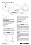
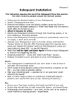
The HX40/40AM
Features:
Unique Dual Pyro-Elements
Anti-Masking
Mounting Height 8.3’ to 10’
Parts included:
Main unit, Base, Bracket, Lens, Hood, Hardware, Battery
Leads, Alarm Cables & Area Masking Seals
In preparation, remove the wire knockouts on the Base Unit
prior to installing the Bracket.
Next, remove the wire sponge and save in a secure
location
Now lets move on to Installing the Bracket.
First pop the tab open to locate the adjustment screw inside the
bracket.
Loosen the screw to open the Bracket.
Note, there are two ways to install the Bracket.
90 degrees to the right, or….
90 degrees to the left. Depending on the application.
Adjust the Bracket at a 45 degree angle and run the wire
through the rear of the Bracket.
Pull the wire through to be able to wire to your terminals.
Install the Bracket using the hardware provided.
With the sponge removed, feed your wire through
the Base unit.
Then replace the Sponge! Next, Install the adjustment
screw. Be sure not to tighten too much to be able to adjust
the detector. Once adjusted, then tighten the screw.
For convenient access to terminals, the detector
can be placed facing toward the housing by the
tabs on the side
Once wiring is complete, rotate the main unit and
install into the Base.
Install the main unit by grasping the Sun Shield to avoid
touching the Elements.
You may adjust the detector downward for a downgrade slope.
(Do not change the detection range with the bracket, use the
masking seal.
Or you may adjust it for an upward slope.
(Do not change the detection range with the bracket, use
the masking seal)
For a level adjustment, set the detector to 0
degrees found on the right hand side.
Make sure to replace the cover to the cylinder.
Your installation is complete!
Use area masking seals to limit detections based
on your application (Do not change the detection range
with the bracket)
Area masking seals can be installed inside
the lens for unwanted detection areas
Let’s talk about the HX40RAM! It’s the wireless version of the
HX40 Standard Model. You will need to provide a Universal
Transmitter that fits in the back box. Transmitter dimensions can be
found on page 4. of the user manual.
First, determine if you are Battery Sharing or Not Battery Sharing.
Battery sharing is when power supplied is available from the battery
box to power both HX40RAM and Transmitter.
If you are Not Battery Sharing, you will need to provide batteries to
power both the HX40RAM and the transmitter.
Remove the Battery case by grasping the claws on each side and
pulling straight out from the main unit.
Now you are ready to install batteries!
When Battery Sharing:
Use 3 of each:
CR123A
CR2’s
1/2AA
When Not Battery Sharing:
Use 3 of each:
CR123A or
CR2’s
Do not use ½ AA batteries.
Place the battery leads (Included in Box) and a dummy
battery in the battery case of the transmitter
Depending on the size of the transmitter, there are two
ways to mount the battery box. Example:
The upper position
Place the velcro tape here.
And mount the transmitter here.
In the lower position.
Place the velcro tape here.
And mount the transmitter in this position.
Wire battery power leads from battery box to the
Main Unit terminals.
Wire alarm cables from the transmitter to the alarm
NO/NC/Com terminals on the Main Unit.
Once the transmitter is installed, you are ready to
install the Main unit to the back Box.
Finally, install the hood for added protection from
the elements. This helps with Sun, Rain and even
Snow.
Place the battery leads (Included in Box) and a dummy
battery in the battery case of the transmitter
Mounting the Wall Tamper (Option)
A commercial magnet switch may be mounted as a wall
tamper. Installation space is provided on the back of the
main unit.
Set up Functions of the HX40