1
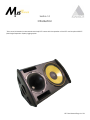
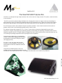
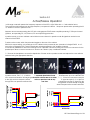
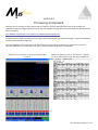
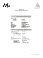
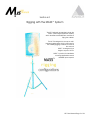
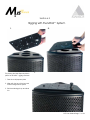
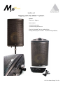
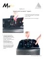
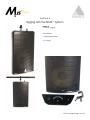
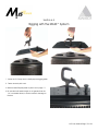
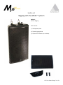
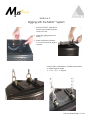
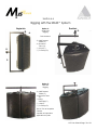
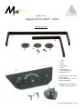
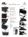
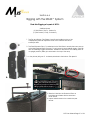
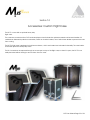
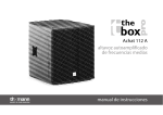
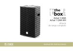
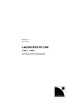
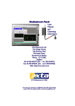
Contents:
Section 1:
Introduction p.4
Section 2:
The essential multi-purpose box p.5
ND-15 p.5
Cabinet Symmetry p.5
Section 3:
Active/Passive operation p.6
Section 4.:
Processing and Presets p.7
Section 5:
Technical Specifications p.8
Section 6:
MASS™ rigging p.9-21
6.1 Warning
6.2 Multi-Purpose Plate
6.3 Pole Mont Rigging
6.4 C-Clamp Rigging
6.5 Flytrack Rigging
6.6 Single and Dual Axis Rigging
Section 7:
Custom Flightcase p. 22
It is compulsory to read this user manual before operating M15’s . Supervision and competency
are the responsibility of the system owners and operators. Owners and operators are responsible
for inspecting the rigging and ensuring that it has not been damaged in transport, from misuse, or
wear and tear. M15 loudspeakers are easily capable of generating high sound pressure levels that can
cause permanent hearing damage and should be operated by personnel with experince in professional
audio.
M15 User Manual Page of 24
Section 1.0
Introduction
This manual is intended to demonstrate and help M15 owners with the operation of the M15 and its optional MASS™
(Multi Angle Suspension System) rigging system.
M15 User Manual Page of 24
Section 2.0
The Essential Multi-Purpose Box
The M15 is a multi-purpose high output enclosure, that can be used as a stage monitor, FOH system, center enclosure,
or as a fill device.
The M15’s symmetrical cabinet design facilitates mirror imaging when used as a stage monitor by maintaining the
same projection angle. The indescreet simplified Adamson logo indicates the low LF driver end. When placed side to
side with the logos facing the low frequencies will couple. When placed on the opposite side, the horns will couple
The M15 employs a switch which allows bi-amped or passive operation. It uses internal crossover circuitry when in
passive mode, which is automatically by-passed when in active mode.
The cabinet is loaded with a single ND-15L, a 15 inch LF driver which incorporates a lightweight long excursion
neodymium magnet, enhancing output, delivering superior powerhandling and providing consistently stable low end
frequency response.The ND-15’s basket utilizes an enlarged heat sync and thermal fins which draw heat away from the
coil, lowering its operating temperature and improving thermal compression.
Constructed from Baltic birch, it is designed to
accept a multi-purpose rigging plate that allows
several different methods of flying the cabinet
(see Rigging section).
The ND-15 is the only driver with zero-axial
modes in it’s entire passband. (60-800 hz) This
substantially increases the linearized mid-band
response.
Compared to traditional paper cones, the
multilayer Kevlar cone along with advanced cone
architecture, offers superior performance, zero fatigue and eliminates cone modes in the passband.
Th
all
res
lac
tra
op
a5
M15 User Manual Page of 24
Section 3.0
Active/Passive Operation
In full range mode with presets the frequency response of the M15 is 60hz-18khz with a +-3db variation factor.
The crossover point between low and high frequency components is 800hz. . Always use presets when operating the M15, whether in active or passive mode.
Adamson recommends powering the M15 with a Lab.gruppen fP3400 stereo amplifier producing 1100w per channel
@8ohms, and providing AC, VHF, thermal, DC and clip limiting protection.
In passive mode, up to two cabinets can be linked on one channel. In passive mode all signals are routed to one
channel of the fP3400.
To select active mode, switch the protected toggles on the rear of the cabinet.
With the bi-amped setting, you enable up to two cabinets to be powered by two channels of a single fP3400. In a 2way active configuration the LF and HF signals are routed sepearately to the amplifier channels.
It can also be paralleled to other M15’s through four NL-4 Speakon connectors. Using one of the four connectors for the
speaker input allows a second connector to function as a feed to jump additional cabinets.
1. Remove the backplate to access the dipswitches. Choose active or passive mode and replace the cover with the
indicator facing the appropriate direction.
In active mode the Lap.gruppen
fP3400powers up to two cabinets. Pins
1+/1- of the four connectors carry the
LF signal and pins 2+/2- of the four
connectors carry the HF signal. The pin
configuration is automatically changed
when Bi-amped active mode is selected.
1. exposed dipswitches-Ensure
In passive mode , Pins 1+/1- of all four
NL4 connectors feeds the full range signalthat both switches are set to either
active or passive mode at any
to the High and Low frequency drivers,
one time.
through their own passive crossover units.
M15 Passive
M15 Active
M15 User Manual Page of 24
Section 4.0
Processing and presets
Adamson recommends processing signals with the Adamson M Series digital processor, but factory presets are
available for approved digital signal processors, and are available through either the official Adamson website (link below) or by request.
www.adamsonproaudio.com technical_support/presets/index.htm
M-series Processor Presets are determined through polar measurements and spacial averages to optimize equalization,
crossover points and time alignment.
M15 Preset librairies for XTA’s processors can be obtained from the Adamson website, by request from your local
Adamson distributor or the Adamson Head office, and are applied using audio-core software.
Adamson’s X-Link software controls the M-Series Digital
Processor.
Below is a reference chart of XTA DP224 V.11 presets.
For up to date presets check the above website link.
M15 User Manual Page of 24
Section 5.0
Technical Specifications
M15 User Manual Page of 24
Section 6.0
Rigging with the MASS™ System
The M15 optional accessories include the
MASS™ (Multi Angle Suspension System)
which features several different methods of
flying the cabinet.
The M15 is designed to accept a multipurpose rigging plate, which is the base for
the following rigging methods covered in
the manual.
MASS™ is designed for a
single or a pair of M15’s.
MASS™ is perfect for installation
or touring applications and is
available upon request.
M15 User Manual Page of 24
Section 6.1
Rigging with the MASS™ System
When mounting the M15 with MASS™, ensure the boxes are securely fastened and mounted properly. Suspended
speakers should always be reinforced with steel safety cable and inspected by an experienced crew member.
When pole mounted, verify the stand is placed on a level surface, the tripod legs are fully extended and do not
present a trip hazard. in adverse outdoor conditions it may be necessary to support the base of the stand with
additional weight.
It is good practice to regularly inspect any cabinets housings for signs of wear, and load bearing bolts in mounting
devices. MASS™ is intended for use with the M15 only.
M15 User Manual Page 10 of 24
Section 6.2
Rigging with the MASS™ System
1.
For placing the Multi-Purpose plate in
place for all MASS™ rigging methods
2.
3.
1. Take the multi-purpose plate
2. Allign with the top of the box and
fit the locking hub into place
3. Pull the retaining pin up and slide
it in.
M15 User Manual Page 11 of 24
Section 6.3
Rigging with the MASS™ System
Option1:
Pole Mount - Rigging
Parts needed:
(1) Multi-Purpose plate
(1) Polemounting attachment
(Part not included. Can be ordered from
Koenig & Meyer part number - 195/8 Mounting Adapter)
M15 User Manual Page 12 of 24
Section 6.3
Rigging with the MASS™ System
1. Screw the polemounting piece horinzontally
to the multipurpose plate. (1/4’ 20 machine
screw, 1/2” long.
2. Fasten the plate to the M15 as on page 11.
3. In the event that you have
the “flytrack” installed onto the
multipurpose plate and do not
want to uninstall it, you can screw
the pole mounting piece
verticallly. This will cover a part of
the protractor, and
therefore we suggest using
a horizontal pole mount
placement whenever possible.
Note- In this position the cabinet
is not gravity centered, therefore
ensure the tripod legs are fully
extended and reinforced as
required.
M15 User Manual Page 13 of 24
Section 6.4
Rigging with the MASS™ System
Option 2:
C-Clamp - Rigging
Parts needed:
(1) Multi-purpose plate
(1) C-clamp
M15 User Manual Page 14 of 24
Section 6.4
Rigging with the MASS™ System
1. Screw the C-Clamp into the Multi-purpose rigging plate.
2. Fasten securely with a nut
3. Slide the Multi-Purpose plate to place as on page 11.
4. Be sure the bolt head’s height is not greater than the
1/4” countersink allows, to avoid cosmetic damage to
the box.
M15 User Manual Page 15 of 24
Section 6.5
Rigging with the MASS™ System
Option 3:
Fly-Track Rigging
Parts Needed:
(1) Multi-pupose plate
(2) Flytrack rigging pieces
(2) Suspension Hardware (not included)
M15 User Manual Page 16 of 24
Section 6.5
Rigging with the MASS™ System
1. Secure the MASS™ flytracks into
position with provided machine
screws.(3/8 16th)
2. Attach the rigging plate as on
page 11.
3. Attach suspension hardware
if a more pronounced angle is
required.
Flytrack option is adjustable to 5 different placements
for varied degreed angles.
-9, -5.5, 0, +5.5, +9 degrees
M15 User Manual Page 17 of 24
Section 6.6
Rigging with the MASS™ System
Single Axis
B.
A.
Dual Axis
Option 4:
Single Axis
Rigging
D.
F.
Parts needed:
D.
(2) Multi Purpose
Plates (A.)
(2) Protractor
Discs (B.)
(1) U-bar (C.)
(1) C-Clamp (D)
B.
A.
E.
C.
C.
Option 5:
Dual Axis
Rigging
(2) Multi Purpose
Plates (A.)
(2) Protractor Discs
(B.)
(1) Swing
Assembly (E.)
(1) L-bar (F)
(1) C-Clamp (D)
The M-15 is an Arrayable
Cabinet
capable of suspension
applications in pairs.
M15 User Manual Page 18 of 24
Section 6.6
Rigging with the MASS™ System
Detailed parts list
1.
2.
3.
4.
5.
6.
1. U-bar
2. L-bar
3. U-Disc
4. Spacer Disc
5. L-Disc
6. Lever Screws
7. Multi Purpose plate
8. Protractor Disc
7.
Note that parts 4-6 (top photo)
as well as parts
6 & 8 (bottom photo) come
already assembled.
(Additional tools you will need
is a Phillips Head Screwdriver)
6.
8.
M15 User Manual Page 19 of 24
Section 6.6
Rigging with the MASS™ System
Single Axis
Dual Axis
1. Attach the Protractor Disc to
the Multi Purpose Platewith
attached lever pins. ( x2 )
Attach the Multi Purpose
Plates to the M15 as on p.11
1.
6.
2-4. Slide the U-bar into the
Protractor Disc, and insert the
quick release push-pins on both
sides.
5. (Attach C-Clamp to the U-bar. If
rigging as Dual Axis continue
through steps 7-12.)
7. Screw the U-Disc on to the
U-bar.
2.
7.
8.
8. (Place the Spacer Disc on top
of the U-Disc, the Spacer Disc is
usually permanently attached
to the L-Disc.)
9-11. Place the L-Disc on the
U-Disc, insert the
Machine Bolt and fasten it
from underneath. Then attach the leaver
screws on the top side.
3.
12. Attach
C-Clamp
to the U-bar
and Inspect
attachments
to be certain
they are
secure.
9.
10.
4.
12.
5.
11.
M15 User Manual Page 20 of 24
Section 6.6
Rigging with the MASS™ System
Dual Axis Rigging of a pair of M15’s
Additional parts
(2) Twin Plates (Top A.) (Bottom B.)
(12) Set Screws (6 x top, 6 x bottom)
1. The Top and Bottom Twin Plates (A and B) are installed on top of the
multipurpose plates at respective ends of the cabinets with six set
screws per side.
C.
2. The Dual Protractor Disc (C) is attached to the Twin Plate in exactly the same way as
to the Multi Purpose Plate, but part (C) is only used for dual cabinet rigging. Plate (B)
with the fastening toggles attached is installed on the bottom of the array (when in
an upright position.) Plate (A) is attached to the top of the array.
3. In the picture (left) part C. Is already attached to the bottom Twin plate B.
A.
B.
Three Set Screws are fastened on each
side of the Twin Plates. (Both Top and
Bottom.) The Twin Plates screw into
designated holes on the Multi Purpose
Plates to ensure secure rigging.
3. Slide the U-bar into the Protractor Discs on
both sides and fasten with the attached
Lever Screws.
4. Inspect attachments to be certain they are
secure.
M15 User Manual Page 21 of 24
Section 7.0
Accessories: Custom Flight Case
The M-15 comes with an optional heavy duty
flight case.
The cases are constructed from PVC laminated plywood and include zinc plated recessed catches and handles. All
cabinets are fastened by aluminum extrusions, and sit on six swivel castors, two of which have brakes to prevent the case
from moving.
The M-15’s flight case is designed to hold two enclosures , which are loaded and unloaded horizontally. The case interior
is lined with protective heavy-duty foam.
The NL4 connectors are exposed through an access port on top of the flight case, so when it is open, the M-15’s can
easily be tested without having to remove them from the case.
M15 User Manual Page 22 of 24