1
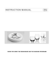
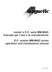
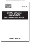
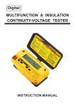
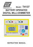
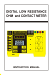
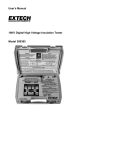
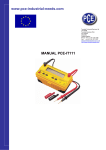
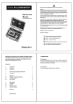
User’s Guide
Model 380580
Battery Powered
Milliohm Meter
Introduction
Congratulations on your purchase of Extech’s Model 380580 Battery Powered Milliohm Meter. This
device offers five resistance ranges with resolution as low as 0.1mΩ. The 4-wire Kelvin clip connection
ensures optimum accuracy. Typical applications include transformer, motor coil, and PC Board
resistance measurements. This professional meter, with proper care, will provide years of safe reliable
service.
Meter Description
1.
2.
3.
4.
5.
6.
7.
Current Terminals
Potential Measurement Terminals
LCD Display
Start/Stop Test Button
Range Select/Power Switch
LED Error Lights
• No Test/Over Temperature
• RP Voltage Regulation
• RC Current Regulation
Current/Range Table
Leads
Current Leads- Banana plug to alligator clip
C1- Green
C2- Blue
Voltage Potential Leads- Banana plug to alligator clip
P1- Red
P2- Black
Kelvin Clips- Banana Plugs (2) to Kelvin Clip
Red (P1) Green (C1)
Black (P2) and Blue (C2)
Measurement Considerations
1.
Do not apply voltage to the meter input terminals. Meter damage may result.
2.
Always insure that the circuit to be measured is switched OFF, isolated and completely deenergized before connecting the test leads.
3.
If the Over Temperature LED (NO TEST) indicator is lit, allow the instrument to cool down
before proceeding further.
4.
The RC led indicates when the test current falls out of regulation. Selecting a higher range
may eliminate the condition.
5.
The RP led indicates when the voltage on the device under test is too high. Selecting a lower
range may eliminate the condition.
6.
If either the RC or RP led is on, the measurement may be in error.
7.
The current terminals are fuse protected.
8.
Keep the potential test leads as short as possible. Long leads may introduce noise.
9.
When using the four separate alligator clip leads always place the current leads outside the
potential leads.
2
380580-EN-V2.3-4/12
Preliminary Checks
Current Regulation Check
1. Connect the current leads C1 and C2 to the meter.
2. Set the function switch to the 200.0mΩ range.
3. Momentarily press the TEST RP button. The meter will
intermittently beep and RC will light
4. Short the current leads C1 to C2.
5. The RC LED should go off, indicating that the meter is
operating correctly.
6. Momentarily press the TEST RP button to stop the test
7. The meter will return to NO TEST status.
Voltage Measurement check
1. With the current test leads C1 and C2 shorted, connect and
short the potential (voltage) leads P1 and P2.
2. Set the Function switch to the 200.0mΩ position. The NO
TEST status LED will light.
3. Momentarily press the TEST RP button. (the meter will
intermittently beep)
4. The display should indicate 00.0
5. Momentarily press the TEST RP button to stop the test.
The NO TEST status LED will light.
6. Remove the shorts from P1 and P2, and C1 and C2 and
7. Short the test leads P1 to C1 and P2 to C2
8. The RP LED as well as the NO TEST status LED should
light indicating an over-voltage or over-range
9. Turn the rotary selector switch to OFF
Polarity check
1. Short the test leads P1 to C2 and P2 to C1 together.
2. Set the Function switch to the 200.0mΩ position.
3. The “-1“ negative indicator should appear in the display.
Operation check
Use the Kelvin clips for this test
1. Short the all the leads (P1, P2 ,C2,C1) together. The P1,
P2 ,C2,C1 order is important.
2. Set the Function switch to the 200.0mΩ position. The
NO TEST status LED will light.
3. Momentarily press the TEST RP button. (the meter will
intermittently beep
4. The display should indicate near 00.0 (depending on
the test clip connections) and both RP and RC LEDs
should remain off.
5. Momentarily press the TEST RP button to stop the test.
Note: These tests can be performed on any range.
3
380580-EN-V2.3-4/12
Measurement Procedure
1.
Select the desired measuring range on the meter. If the resistance of the device is unknown,
start with the highest range and work downward.
2.
Clip the test leads onto the device under test. Note: When using the 4-wire/4 alligator clip
test leads, it is recommended that the current test leads be outside of the potential test leads
(as shown in the diagram below).
3.
For a short test duration of 10 seconds, press the TEST RP button for less than 2 seconds.
This EnerSave™ feature can be used to conserve battery power.
4.
For a long test duration of 60 seconds, press the TEST RP button for more than 3 seconds.
5.
During the test, the meter will intermittently beep. At the end of the test or if the test is
stopped, “HOLD” will appear and the last reading will be “frozen” on the display.
4
380580-EN-V2.3-4/12
Measurement Principles
The test current flows through the resistance from the Current+ (C+) terminal to the Current - (C-)
terminal. The P+ and P- (POTENTIAL) terminals measure the voltage drop across the device under
test only, thus eliminating the lead and contact resistances. The meter displays the resistance
based on the test current and the measured voltage; refer to the equation below:
C+
P+
Volts
Current
P-
C-
Rx = Vx / Is
Where:
Vx is the voltage drop across the device under test;
Is is the test current;
Rx is the resistance of the device under test.
Thermal Effects
Temperature can have a significant effect on the performance of millohmeter due to the temperature
coefficient of the resistance under test and thermal EMF’s across dissimilar conductors.
Most conductors have a large temperature coefficient of resistance
For example: 0.4%/°C for copper. A copper conductor that has a resistance of 10.00m ohm at 20°C
will increase to 10.40m ohm at 30°C. This should be taken into account..
A current going through a resistance will also elevate the temperature so duration of the test can also
change the resistance.
5
380580-EN-V2.3-4/12
BATTERY INSTALLATION
WARNING: To avoid electric shock, disconnect the test leads from any source of voltage before
removing the battery cover.
1.
Turn power off and disconnect the test leads from the meter.
2.
Open the rear battery cover by removing two screws (B) using a slotted head screwdriver.
3.
Insert the batteries into battery holder, observing the correct polarity.
4.
Put the battery cover back in place. Secure with the screws.
You, as the end user, are legally bound (Battery ordinance) to return all used batteries and
accumulators; disposal in the household garbage is prohibited!
You can hand over your used batteries / accumulators at collection points in your community
or wherever batteries / accumulators are sold!
Disposal: Follow the valid legal stipulations in respect of the disposal of the device at the
end of its lifecycle.
REPLACING THE FUSES
There are three fuses:
Power Supply Fuse
1.
2.
3.
The power supply fuse is located in the battery compartment.
Remove the two screws to open the battery compartment.
Always use a fuse of the proper size and value.
Current Circuit Fuse
1. Fuse protection for the current terminals.
2. If the fuse is blown, the RC LED will stay on.
3. The fuse is located under the printed circuit board.
4. There are 4 mounting screws that have to be removed.
5. Two screws are located under the black feet on the bottom of the unit.
6. The other two screws are located in the battery compartment.
7. Remove the battery compartment door and the batteries to access these screws.
8. Always use a fuse of the proper size and value.
Potential Circuit Fuse
1. Fuse protection for the potential terminals.
2. If the fuse is blown, the RP LED will stay on.
3. The fuse is located under the printed circuit board.
4. There are 4 mounting screws that have to be removed.
5. Two screws are located under the black feet on the bottom of the unit.
6. The other two screws are located in the battery compartment.
7. Remove the battery compartment door and the batteries to access these screws.
8. Always use a fuse of the proper size and value.
6
380580-EN-V2.3-4/12
Specifications
General Specifications
Display
Measurement terminals
1.0" (25 mm) LCD (1999 counts)
4-Terminal Kelvin type
Measurement Range
Sampling Time
Over input indication
Operating Temperature
Operating Humidity
Power Supply
Five ranges (see listing below)
Approximately 3 times per second
Indication of "1 - - -"
5ºF to 131ºF (-15ºC to 55ºC)
<80% RH
8 x 1.5V AA Batteries (Approx. 10hrs continuous use)
Weight
Dimensions
3.3 lbs (1.5kg)
9.8x7.5x4.3" (250x190x110 mm) with cover
Range Specifications
Range
200.0mΩ
Resolution
0.1mΩ
Test
Current
100mA
Accuracy
(%reading )
± 0.5% + 2 digits
Open Circuit
Voltage
4.2V
2000mΩ
1mΩ
100mA
± 0.5% + 2 digits
4.2V
20.00Ω
0.01Ω
10mA
± 0.5% + 2 digits
4.2V
200.0Ω
0.1Ω
10mA
± 0.5% + 2 digits
4.3V
2000Ω
1Ω
1mA
± 0.5% + 2 digits
4.4V
International Symbols
This symbol, adjacent to another symbol or terminal, indicates the user must refer to the
manual for further information.
This symbol, adjacent to a terminal, indicates that, under normal use, hazardous voltages
may be present
9.
Double insulation
7
380580-EN-V2.3-4/12
Warranty
EXTECH INSTRUMENTS CORPORATION (a FLIR company) warrants this instrument to be free of defects in parts and workmanship for
one year from date of shipment (a six month limited warranty applies to sensors and cables). If it should become necessary to return the
instrument for service during or beyond the warranty period, contact the Customer Service Department for authorization. Visit our website
www.extech.com for contact information. A Return Authorization (RA) number must be issued before any product is returned to Extech. The
sender is responsible for shipping charges, freight, insurance and proper packaging to prevent damage in transit. This warranty does not
apply to defects resulting from action of the user such as misuse, improper wiring, operation outside of specification, improper maintenance
or repair, or unauthorized modification. Extech specifically disclaims any implied warranties or merchantability or fitness for a specific
purpose and will not be liable for any direct, indirect, incidental or consequential damages. Extech's total liability is limited to repair or
replacement of the product. The warranty set forth above is inclusive and no other warranty, whether written or oral, is expressed or
implied.
Calibration and Repair Services
Extech offers repair and calibration services for the products we sell. Extech also provides NIST certification for most products. Call the
Customer Service Department for information on calibration services available for this product. Extech recommends that annual calibrations
be performed to verify meter performance and accuracy.
Support lines: U.S. 877-439-8324, Intl. 603-324-7800
Technical support: Option 3; E-mail: [email protected]
Repair & Returns: Option 4; E-mail: [email protected]
Product specifications subject to change without notice
Visit our website: www.extech.com
Extech Instruments Corporation, 9 Townsend West, Nashua, NH 03063
ISO 9001 Certified since 1995
8
380580-EN-V2.3-4/12