1
European Organisation for Astronomical Research in the Southern Hemisphere
Programme: VLT
Project/WP: Science Operations
Guidecam User Manual
Document Number: ESO-258369
Document Version: 1.1
Document Type: Manual (MAN)
Released On: 16.6.2015
Prepared by:
Giovanni Carraro, Monika Petr-Gotzens
Validated by:
Stephane Brillant, Steffen Mieske
Approved by:
Andreas Kaufer
ESO - Karl-Schwarzschild-Str. 2 - 85748 Garching bei München - Germany
www.eso.org
Doc. Number:
Guidecam User Manual
Released on:
Page:
Authors
Name
Affiliation
G. Carraro
ESO-Chile
M. Petr-Gotzens
ESO-Garching
Change Record from previous Version
Affected Section(s)
Changes / Reason / Remarks
Document Classification: ESO Internal
ESO-258369
Doc. Version: 1.1
2 of 22
Doc. Number:
Guidecam User Manual
ESO-258369
Doc. Version: 1.1
Released on:
Page:
3 of 22
Contents
1. Scope .................................................................................................................................. 4
2. Related Documents ............................................................................................................. 4
2.1 Applicable Documents.................................................................................................. 4
2.2 Reference Documents.................................................................................................. 4
3. Introduction.......................................................................................................................... 4
3.1 Definitions, Acronyms and Abbreviations ..................................................................... 5
4. Start up and common features ............................................................................................ 6
4.1 Telescope pointing ....................................................................................................... 6
4.2 Guide star (GS) selection ............................................................................................. 7
4.3 Science target selection ............................................................................................... 9
4.4 Reference star(s) selection .......................................................................................... 9
4.5 Offset list .................................................................................................................... 10
4.6 Jitter Box .................................................................................................................... 11
4.7 Finding chart (FC) generation .................................................................................... 11
5. Interface with P2PP ........................................................................................................... 13
6. Instrument specific features .............................................................................................. 15
6.1 VIMOS ........................................................................................................................ 15
6.1.1 IMG and PRE .................................................................................................... 15
6.1.2 IFU .................................................................................................................... 15
6.1.3 PILMOS ............................................................................................................ 16
6.2 VISIR .......................................................................................................................... 17
6.2.1 IMG ................................................................................................................... 18
6.2.2 SPEC ................................................................................................................ 18
6.3 HAWK-I ...................................................................................................................... 18
6.3.1 Non-AOF ........................................................................................................... 18
6.3.2 AOF-TTS-free ................................................................................................... 18
6.3.3 AOF ................................................................................................................... 18
6.3.4 Pointing offsets ................................................................................................. 19
7. Keyboard shortcuts ........................................................................................................... 19
8. List of keywords passed to P2PP ...................................................................................... 20
8.1 VIMOS ........................................................................................................................ 20
8.2 VISIR .......................................................................................................................... 21
8.3 HAWK-I ...................................................................................................................... 21
Document Classification: ESO Internal
Doc. Number:
Guidecam User Manual
ESO-258369
Doc. Version: 1.1
Released on:
Page:
4 of 22
1. Scope
This document introduces the use of the Unified GuideCam tool, a Java-based
observation preparation tool that aims to unify as many as possible, potentially all,
ESO/VLT instrument-specific preparation tools in just one tool, the unified GuideCam tool.
The first public version of the unified GuideCam tool is described here and deals with
VIMOS, VISIR, and HAWK-I.
2. Related Documents
2.1 Applicable Documents
The following documents, of the exact version shown, form part of this document to the
extent specified herein. In the event of conflict between the documents referenced herein
and the content of this document, the content of this document shall be considered as
superseding.
AD references shall be specific about which part of the target document is the subject of
the reference.
AD
Document Nr.
Version
Document Title
AD1
VLT-MAN-ESO-3486
HAWKI User Manual
AD2
VLT-MAN-ESO-3509
VIMOS User Manual
AD3
VLT-MAN-ESO-3514
VISIR User Manual
Part / Section
2.2 Reference Documents
The following documents, of the exact version shown herein, are listed as background
references only. They are not to be construed as a binding complement to the present
document.
RD Nr.
Document Nr.
RD1
VLT-MAN-ESO-14610-3512
Version
Document Title
VISIR GuideCam User Manual
3. Introduction
This document describes the use of the Unified Guidecam tool (GUCT). GUCT is a highly
interactive tool that unifies individual instrument-specific phase2 preparation tools, which
in previous ESO observing periods were offered only as stand-alone single tools. In the
current version, GUCT is offered for HAWK-I, VISIR, and VIMOS, and replaces and
unifies the VISIR specific GuideCam tool, the VIMOS specific GuideCam tool, as well as
PILMOS. Furthermore, GUCT is strongly recommended to be used for HAWK-I
observation preparation and the creation of finding charts for VIMOS, VISIR or HAWK-I
OBs. It is mandatory to use GUCT for the preparation of VIMOS imaging, pre-imaging,
and PILMOS OBs. The tool uses the Aladin Sky Atlas for the visualization of the telescope
and instrument fields. Also, GUCT can directly interact with P2PP (version 3.4.2 or higher)
Document Classification: ESO Internal
Doc. Number:
Guidecam User Manual
ESO-258369
Doc. Version: 1.1
Released on:
Page:
5 of 22
in order to attach finding charts, to retrieve information on the instrument/mode setup or to
propagate acquisition template parameters, such as guide star coordinates, to the OB.
3.1 Definitions, Acronyms and Abbreviations
This document employs several abbreviations and acronyms to refer concisely to an item,
after it has been introduced. The following list is aimed to help the reader in recalling the
extended meaning of each short expression:
AO
AOF
Dec
FoV
FC
GP
GS
GUCT
OB
P2PP
RA
RS
UCD
VLT
WFS
Adaptive Optics
Adaptive Optics Facility
Declination
Field of View
Finding Chart
Guide Probe
Guide Star
Guide Cam Tool
Observing Block
Phase 2 Proposal Preparation
Right Ascension
Reference Star
Unified Content Description
Very Large Telescope
Wave Front Sensor
Document Classification: ESO Internal
Doc. Number:
Guidecam User Manual
ESO-258369
Doc. Version: 1.1
Released on:
Page:
6 of 22
4. Start up and common features
Using GUCT is relatively simple. After download and installation (see
http://www.eso.org/sci/observing/phase2/SMGuidelines/GUCT.generic.html), issue the
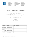
command ./GuideCamTool in the /bin directory of the GUCT path. Figure 1 illustrates the
two main panels which pop up:
1. the control panel (on the left) and
2. the Aladin window (on the right)
Figure 1: Guidecam tool components. Control window on the left, and Aladin
window on the right.
The GUCT control panel allows the user first of all to select an instrument: VIMOS, VISIR,
or HAWK-I. Once an instrument is selected, it is also possible to select among specific
instrument modes. Alternatively, the instrument and mode can be retrieved from P2PP
using the “Fetch OB info from P2PP” button at the top of the GUCT control panel, if P2PP
is running and an OB with at least an acquisition template has been defined within P2PP
and is selected.
In the following we describe the main GUCT features offered via the GUCT control panel.
These features are mostly non-instrument specific (indicated otherwise).
4.1 Telescope pointing
All instruments
The first step is to point to a target/target field on sky. This is done either by entering the
target coordinates (in J2000 and using the format hh:mm:ss.ss and dd:mm:ss.ss) in the
RA and Dec fields of the ‘Target field center’ section of the control panel, or by writing the
Document Classification: ESO Internal
Doc. Number:
Guidecam User Manual
ESO-258369
Doc. Version: 1.1
Released on:
Page:
7 of 22
target name in the ‘Object’ field (and pressing enter!), which will be resolved by Sesame
using Simbad, NED and VizieR. You may also fetch the coordinates from P2PP if you
already have an OB with OB target coordinates defined.
When pressing the ‘Point Telescope/Update View’ button, GUCT will download either the
respective DSS image (in case the selected instrument is VIMOS) or the 2MASS image
(in case of VISIR and HAWK-I). The image on sky will appear in the Aladin panel, together
with some instrument specific features: the instrument field of view (in yellow), the unvignetted and 10% vignetted telescope fields of view (in green and red, respectively), and
the guide probe rail (in cyan).
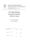
Figure 2: The VIMOS imaging FoV outlined in yellow, superimposed on the DSS
image shown in the Aladin sky view. In red is the radius corresponding to the
maximum search radius for suitable guides stars, which are indicated in cyan.
The example in Figure 2 is for VIMOS in imaging mode pointing to the Galactic star
cluster NGC 2627. The target is located, by default, at the center of the field and shown as
a yellow circle.
Besides, the instrument field of view can be rotated using the rotation slider of the GUCT
control panel (the resolution is 0.1 degrees). The slider can also be adjusted with the
up/down or left/right arrows. The default rotation is 90 deg for all VIMOS modes and 0 deg
for HAWK-I and VISIR.
4.2 Guide star (GS) selection
All instruments
Using the ‘Tool’ pull down menu and selecting the ‘VLT Guide stars’ tab, it is now possible
to define one or more telescope guide star(s). Candidate GSs are drawn from the UCAC4
catalog and shown in the Aladin panel as cyan circles, with an arrow indicating the proper
motion direction and its length being proportional to the proper motion value. The radius of
the circle is proportional to the stellar magnitude. Proper motion components can be
toggled on/off by clicking on the PMfilterGS plane on the right hand side of Aladin window.
By default, the displayed GSs are within the magnitude range 11 to 13.5 mag, but the
range can be changed by editing the ‘magnitude filter’ min/max values in the control
Document Classification: ESO Internal
Doc. Number:
Guidecam User Manual
ESO-258369
Doc. Version: 1.1
Released on:
Page:
8 of 22
window (see Figure 3), in case the standard mag range does not provide suitable GSs for
a certain target field. The minimum and maximum permitted values are 10 and 14. With
the faintest GSs, some degradation of the active optics correction might take place,
depending on seeing, airmass, Moon, possible extinction by thin cirrus, and position of the
GS in the field of view (vignetting beyond 11 arcminutes). To the extent this is possible,
stars brighter than 13.5mag should be chosen. Stars close to the center of the field
(without causing vignetting) are preferred. Too bright objects may result in poorer
correction as well.
How do you actually chose a GS? Simply select with a mouse click the desired GS, and
the projected shadow of the telescope Guide Probe (GP) onto the telescope focal plane
will show up, as illustrated in Figure 3. Note: the selection of a guide star is only possible
if the select button is on in the right hand side of the Aladin window (see Figure 4). Also
note that the selection is effective only when the mouse pointer turns into a hand symbol
(it might be necessary to zoom in a bit). The selected star will blink. Its coordinates,
magnitudes at different filters, proper motion etc. are reported in the bottom part of the
Aladin window. The GP can be positioned on a given guide star in 2 positions, called
positive and negative (POS and NEG). The latter is referenced to as alternate position. By
selecting the corresponding button ‘Alternate probe position’ in the GUCT control panel,
the probe will be positioned on the same star on its alternate position. This option may
allow to reduce or even remove the vignetting that may be present in the other position.
Vignetting of the instrument FoV occurs whenever the GP shadow intercepts the
instrument FoV (yellow rectangles).
Figure 3: Example of Guide Star selection. The guide probe (GP) shadow and the
GP rail are indicated in cyan. The magnitude range of the shown GSs can be
controlled via the ‘Magnitude filter’ in the control panel.
Once a suitable GS has been identified the selection of the GS is finalized by pressing the
‘Add’ button next to the logged RA/Dec coordinate of the GS in the GUTC control panel.
The GS coordinates and probe position will be added to the GS list. An additional
(alternative) GS can be selected. The list (with max. 2 guide stars) can also be re-ordered.
The coordinates of the first GS in the list will be transferred to P2PP and automatically
Document Classification: ESO Internal
Doc. Number:
Guidecam User Manual
ESO-258369
Doc. Version: 1.1
Released on:
Page:
9 of 22
filled in to the respective OB acquisition template parameters via the “Save finding chart”
action (see Sec 4.7). Both, the first and second GS’s coordinates are saved in the
metadata part of the finding chart.
Figure 4: Aladin select tool
4.3 Science target selection
All instruments except VISIR/spec and VIMOS/ifu
In the control panel use the ‘Tool’ pull down menu and select the science target tab. By
default, the science target is the center of the chosen instrument FOV (target field center)
and marked with a small yellow circle. In case your science target is somewhere else in
the field, it should be marked, with your preferred choice of pointer symbol, in either of the
two ways:
•
enter an offset pair (RA and Dec), which is relative to the target field center
(usually the telescope pointing center) and click on the update button. This will
mark the target, but not apply any telescope offsets (telescope offsets are
discussed in Sec. 4.5). Note that the offsets are in sky coordinates.
•
or click on a specific object or point in the Aladin window.
The science target’s coordinates will appear in the bottom of the UGCT control window
and later be saved in the Finding Chart metadata. The target can be indicated with a
circle, arrow, slit, or resizable box using the pointer pull down menu, and will appear in
yellow in the Aladin window.
4.4 Reference star(s) selection
All instruments
A reference star is typically a bright star used for e.g. blind offsets or for controlling the
pointing of the field in case the actual science target is invisible during the acquisition.
Clearly, not all observations have these specific requirements and hence the reference
star selection is optional for all instruments. To specify a reference star and mark it in a
finding chart, select the reference star tab from the ‘Tool’ pull-down menu in the control
panel. Then, click on the desired star (free selection), the coordinates will appear in the
control panel. The user must then input a label and click on ‘Add’. The label and the
Document Classification: ESO Internal
Doc. Number:
Guidecam User Manual
ESO-258369
Doc. Version: 1.1
Released on:
Page:
10 of 22
reference star, marked with a circle, will appear in red in the Aladin panel (see figure 5);
the reference star will also appear in the reference star list in the control panel, where the
user can add up to three reference stars, re-order or remove them.
Figure 5: Example of reference star selection
4.5 Offset list
All instruments except VISIR
Select the offsets tab in the ‘Tool’ pull down menu (control window) to enter offsets. This
will allow you to visualize step-by-step the offsets that you plan to define in the science
template(s) of the OB. It is particularly useful to check for large offsets if any of the shifted
target fields will be affected by vignetting from the guide probe arm.
Offsets must be provided in arcseconds and are entered manually (see Figure 6). They
can be either in the SKY or DETECTOR coordinate system, consistent with the offset
convention of the respective instrument. The entered offset will appear in the GUCT offset
list by clicking on the ‘Add’ button. By convention, offsets are always relative to the
previous offset.
To apply an offset and see the instrument FOV shifted in the Aladin window, you can
either double click on the row in the list or select it and click on ‘Apply’: the telescope
pointing will shift by the corresponding amount in the Aladin sky view window.
It is possible to re-order the offsets list by selecting a row and clicking on “Move Up” or
“Move Down”. To view the original position of the telescope you can click on ‘Clear’ (see
Figure 6). Sending the list of offsets to the respective instrument science template of the
OB is currently not possible. Therefore, it is recommended to take note of the offsets and
insert them manually into the science template of the actual OB (don’t forget to chose in
the OB the same offset coordinate system, SKY or DETECTOR, as you have selected in
GUCT).
Document Classification: ESO Internal
Doc. Number:
Guidecam User Manual
ESO-258369
Doc. Version: 1.1
Released on:
Page:
11 of 22
Figure 6: Example of offset list
4.6 Jitter Box
All instruments except VIMOS
Using the ‘Tool’ pull down menu, one can select the Jitter Box tab. This feature intends to
show the user the maximum spatial extent, i.e. the borders, of the box within which a
science image could fall, if a jitter box is specified in a science template of an OB. To
display the jitter box in the Aladin sky view window check the “Show jitter box” check box.
A big yellow square, surrounding the instrument FOV (HAWK-I FOV in case of the
example in Figure 7), is the final area covered by the observation (Figure 7).
Figure 7: Example of a jitter box (exterior yellow box) of 60arcsec around a HAWK-I
FoV (right hand side of the Figure). It shows that the 2 bright stars just outside the
Southern edge of the field will most likely fall onto the detectors during a jitter
offset
4.7 Finding chart (FC) generation
All instruments
At the end of the observation preparation with GUCT, i.e. after having completed all the
mandatory and desired optional steps described in the previous sections, a finding chart
should be created (for VIMOS imaging, pre-imaging and PILMOS (showing the selected
GS) the FC creation with GUCT is mandatory). In the finding chart metadata, GUCT saves
the information of the selected GS(s) (coordinates, probe position POS or NEG), the
Document Classification: ESO Internal
Doc. Number:
Guidecam User Manual
ESO-258369
Doc. Version: 1.1
Released on:
Page:
12 of 22
target field center, selected instrument rotation angle and further instrument-specific
parameters. The “create finding chart” action sends relevant parameters directly to P2PP.
Therefore, in order to benefit from the automatic updating of OB parameters, and ensuring
the consistency between the attached FC and actual OB content, it is highly
recommended to have P2PP running and the respective OB highlighted when saving the
finding chart in GUCT. Generating and saving a FC without interfacing to P2PP is
possible, but please note that if the FC is then attached to an OB later, the automatic fill in
of OB parameters or any check on instrument consistency will not work.
To create the FC press “Save finding chart” at the bottom of the GUCT control window. In
case you have forgotten to define some mandatory features (instrument and mode
dependent) GUCT will pop up an error message indicating the required action. Once all
necessary information have been provided, a new pop-up window will appear (Figure 8):
Figure 8: Pop-up window which prompts the user to insert mandatory information
before the FC is created.
Insert all the requested information; these will be saved in the FC metadata and also
appear in the Finding Chart upper left corner. Alternatively, you can have RunID, PI name,
OB name prefilled, if you do a “Fetch OB info from P2PP” from the GUCT control panel
before clicking “Save finding chart”. But be careful, in case the OB that is currently
highlighted in P2PP does not have the same, e.g. target coordinates as your target field in
GUCT or is for a different instrument, these parameters/settings will get overwritten in
GUCT, and your preparatory work might be lost. So, better type in RunID, PI name, OB
name by hand unless you have retrieved these info already at the beginning of your
GUCT preparatory work, in which case it will appear already filled in. When all information
are in place the buttons “Preview” and “Create” will become enabled. You can check how
the FC will look like by pressing the ‘Preview’ button. In general, the created FC will
contain the current content of the Aladin sky view window. An exception to this is VIMOS
pre-imaging, for which the FC will always be centered in the telescope center and display
the whole FOV of the telescope with the guide probe clearly shown; see example in
Figure 9. To send a FC to an OB check that the “Send to P2PP” box is checked.
Document Classification: ESO Internal
Doc. Number:
Guidecam User Manual
ESO-258369
Doc. Version: 1.1
Released on:
Page:
13 of 22
Figure 9: Example of a VIMOS pre-imaging finding chart generated with GUCT.
Some “good to know” reminders:
•
Check that you have the correct OB highlighted in P2PP when sending the FC
from GUCT to P2PP. A finding chart cannot be send to the wrong instrument but it
could be send to the wrong instrument mode.
•
FC names must be unique. It is not allowed to attach an additional FC to an OB if
a FC with identical name is already attached to the same OB.
•
Finding Charts are attached and added sequentially to one and the same OB as
often as they are created and send by GUCT to the same OB, although the
maximum current limit is 5 FCs per OB. Attention: if you have changed any
settings/parameters, e.g. the target field center, in your second, third, … FC that
you are going to attach to the OB, then the OB parameters will also be updated
when sending the second, third, … FC to P2PP.
•
GUCT will always save the FC before sending it to P2PP.
•
GUCT creates FCs in JPEG format and with a maximum size of 1MB.
5. Interface with P2PP
The GuideCam tool can be used in tandem with P2PP (version 3.4.2 or higher). This is
recommended, because it minimizes the user’s efforts and possible mistakes. Figure 10
illustrates how the GuideCam tool is interfaced with P2PP.
Document Classification: ESO Internal
Doc. Number:
Guidecam User Manual
ESO-258369
Doc. Version: 1.1
Released on:
Page:
14 of 22
Figure 10: Schematic of the unified GuideCam Tool - P2PP interface
The recommended sequence of actions is as follows:
•
In P2PP, chose the appropriate run folder and create an OB, with at least the
acquisition template defined. Assign an OB name.
•
In P2PP, insert the OB target RA and DEC coordinates, which are the target field
center coordinates of GUCT.
•
In P2PP, select the OB.
•
In the GUCT control panel, click on “Fetch from P2PP”: the tool will retrieve all
relevant information, including instrument, instrument mode, target coordinates, PI
name, OB name, Run ID…
•
For VIMOS img, pre-img, and pilmos, select the GS and the GP position.
•
In the GUCT, perform all necessary actions to create a finding chart (Sect. 4.1 to
4.6) and click on “Save finding chart”. The window shown in Figure 8 will pop up
with all the relevant information already filled in: Run ID and PI Name are read
only, the OB Name is editable and the Bandpass of the catalog image in use in the
present Aladin window must be entered manually. The “Send to P2PP” checkbox
is selected.
•
Click on “Create”: the finding chart will be attached to the OB in P2PP, and all the
relevant information will be sent back to the acquisition template. See the
Appendix for a list of the generic and instrument/mode dependent information that
are transferred.
The unified GuideCam Tool exports all relevant parameters entered into the GUCT control
panel to the metadata (EXIF section) of the FC. Thereby, these data become available to
the external verification module (EVM) in P2PP, allowing further automatic checks on the
correctness of the OB and the consistency with the FC.
Document Classification: ESO Internal
Doc. Number:
Guidecam User Manual
ESO-258369
Doc. Version: 1.1
Released on:
Page:
15 of 22
6. Instrument specific features
6.1 VIMOS
The current version of GUCT incorporates four VIMOS modes:
•
imaging (IMG),
•
pre-imaging (PRE),
•
integral field spectroscopy (IFU)
•
pre-imageless multi-object spectroscopy (PILMOS)
Please see AD2 for additional details. These modes can be selected using the ‘Mode’ pull
down menu. The default mode is PRE. Jitter offsets cannot be executed in any VIMOS
templates and therefore the Jitter box tab is not available in the ‘Tool’ drop down menu.
6.1.1 IMG and PRE
These modes are basically identical from the GUCT point of view. The only difference is
that in PRE mode the generated finding chart is always centered in the telescope pointing
center and displays the whole field of view ensuring that the guideprobe positioning is
clearly visible. The selection of at least one guide star is mandatory for IMG and
PRE-imaging VIMOS OBs. For PRE-imaging the default value of 90 degrees on sky
rotation angle must not be modified unless a waiver is requested (note: for certain
declinations also 0 degrees rotation angle is permitted). Since the VIMOS acquisition
template for IMG and PRE-imaging is identical, GUCT cannot distinguish between the 2
modes when “Fetch from P2PP” is executed and by default sets the PRE mode. The user
has to change it manually to IMG mode when one actually wants to prepare an
observation for VIMOS IMG. Similarly, the default field rotation angle is 90degree, which
should be changed to the desired angle in case of IMG mode.
6.1.2 IFU
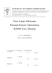
Figure 11 illustrates the GUCT realisation of the IFU mode. The target in this case is M32,
and the tool points the telescope FOV center such that M32 is in the center of the IFU field
of view. For VIMOS set at PA=0deg the center of the FoV of the IFU is located
approximately 667 arcsec West, and 1.6 arcsec South of the telescope field center (see
Figure 11, and please consult AD2 for more information). Again, in the GUCT control
panel the target field center coordinates correspond to the center of the IFU, this is also
consistent with the coordinates that should be specified in the VIMOS/IFU OB.
The guide star selection is optional, but in case it is specified it is recommended to chose
a GS close to the telescope FOV center. A potential problem during IFU OB acquisition is
that the target to be observed cannot be seen in an acquisition image once the IFU has
been deployed. In this case, the telescope FoV usually helps the operator and/or the night
astronomer to check whether or not the telescope is presetting to the desired position. For
this reason, it is required to create a ~5arcmin x 5arcmin FC based on a DSS view of the
field centered on the IFU target coordinates. The field of view of the chosen IFU mode is
automatically drawn by GUCT on the Aladin sky window. Furthermore, it is mandatory to
mark as a reference star, the closest visible star to the IFU center. The label given to the
reference star shall give the distance in arcsec to the IFU FoV center. The requirement of
using the DSS is mandatory, and motivated by the need to ensure that all the objects in
the finding chart can be identified in the Guidecam display used at the telescope.
Document Classification: ESO Internal
Doc. Number:
Guidecam User Manual
ESO-258369
Doc. Version: 1.1
Released on:
Page:
16 of 22
Figure 11: Example of the IFU mode. The IFU FoV is indicated by the small yellow
box located to the West of the telescope FoV center, almost on top of the green
circle.
6.1.3 PILMOS
Users who want to take advantage of the pre-imagingless MOS mode should use the
PILMOS application, which is now incorporated in the unified GuideCam tool. PILMOS
has been offered to VIMOS users since June 2012 and allows to create VMMPS
compliant catalogues and simulated pre-images from user supplied catalogs, which then
serve as input to the MOS preparation software VMMPS. For a full description of PILMOS
please see the PILMOS tutorial in the VIMOS User Manual. The following webpage:
http://www.eso.org/sci/observing/phase2/SMGuidelines/PILMOS.html provides further
recommendations and preconditions under which PILMOS can be used.
Note, users who wish to use PILMOS must download and install the GUCT package
appropriate for their operating system (supported systems: Mac OSX or Linux).
When you select the mode PILMOS in the GUCT control panel a new tab is available in
the ‘Tool’ pull down menu, labelled ‘PILMOS’. If you select it you will see the PILMOS
panel in the control window (Figure 12). However, before running PILMOS you must
select a suitable GS, by using the ’VLT Guide stars’ option under the ‘Tool’ menu. Once
the GS has been defined, and the associated finding chart saved, you can proceed with
PILMOS:
In ‘Catalog file’, upload a contributed catalog that will be passed to PILMOS. This catalog
should contain at least three columns: Object ID, RA and Dec, but can have additional
columns; see the PILMOS tutorial of the VIMOS user manual for further information. Then,
in ‘Output directory’ chose the name of the directory where PILMOS shall save the output
simulated pre-images and catalogs. Finally, press ‘Run PILMOS’.
Document Classification: ESO Internal
Doc. Number:
Guidecam User Manual
ESO-258369
Doc. Version: 1.1
Released on:
Page:
17 of 22
Figure 12: PILMOS panel in the control window
Running PILMOS will take a few seconds during which no feedback is given on the
screen, so please be patient. If everything goes smoothly, you should get four catalog
files, named:
pilmos_B.1_vm_1.cat
pilmos_A.2_vm_1.cat
pilmos_A.3_vm_1.cat
pilmos_B.4_vm_1.cat,
and four simulated pre-images:
pilmos_B.1_sim_1.fits
pilmos_A.2_sim_1.fits
pilmos_A.3_sim_1.fits
pilmos_B.4_sim_1.fits,
which can then be used to run VMMPS.
6.2 VISIR
GUCT supports the two operation modes of VISIR:
•
Imaging (IMG)
•
Slit spectroscopy (SPEC)
VISIR is located at the VLT-UT3 Cassegrain focus, meaning that vignetting is not affecting
the GS selection usable area, and therefore only the red circle (maximum search radius
for guide stars) is indicated in the Aladin sky view, but not the green circle. The selection
of a GS for VISIR observations is not mandatory, but very useful for the following reasons.
Because the sky is extremely bright in the mid-IR which severely limits the sensitivity, plus
the VISIR field of view is small, VISIR images can often appear empty in short to medium
length exposures. However, objects may become visible in longer ones. Combining
different exposures taken on different nights may be tricky if a proper astrometric
alignment is not carried out. Since the overall astrometric accuracy of an image is actually
limited by the accuracy of the GS coordinates, it is strongly recommended that all OBs of
the same field use the same GS, in particular for faint objects. In addition, objects within
(optically) dark molecular clouds may have very few suitable guide stars, such that the
telescope operator will most likely have to spend some time for searching for a good GS.
Considerable amount of telescope time will be saved if such cases are identified before an
OB is started, and an appropriate GS is already specified in the OB.
Document Classification: ESO Internal
Doc. Number:
Guidecam User Manual
ESO-258369
Doc. Version: 1.1
Released on:
Page:
18 of 22
6.2.1 IMG
In IMG mode, once the target has been selected and the field shows up in the Aladin
panel, one can select a guide star. As mentioned above, the selection is optional. GUCT
further allows to visualize the size of a jitter box (max. 10 arcsec) to check if an applied
random jitter might cause problems with other bright nearby stars.
6.2.2 SPEC
In the case of SPEC, GUCT will draw the slit selected from the list provided in the “Size”
pull down menu. The slit will appear in the Aladin window and is oriented in the NorthSouth direction when the position angle on sky is 0. The position angle can be changed
with the rotation slider. The selection of a GS is optional. Jitter is available for this mode,
although only along the direction of the slit. The position of the science target is by default
fixed at the slit center, hence the science target tab of the ‘Tool’ menu is disabled. If for
whatever reason you don’t want your science target at the slit center at the start of the
acquisition procedure, you should specify the appropriate RA/Dec coordinate in the GUCT
target field center box which corresponds to the slit center.
6.3 HAWK-I
The current version of GUCT supports three different HAWK-I modes:
•
Non-AOF (standard imaging without adaptive optics)
•
AOF (adaptive optics assisted imaging)
•
AOF-TTS-free (tip-tilt free, adaptive optics assisted imaging)
Two further modes, Non-AOF fast photometry and AOF fast photometry will be added
in future releases.
The present release of GUCT should be used only for the phase2 preparation of the nonAOF mode, as the AOF is still under commissioning and HAWK-I+GRAAL will be offered
only later.
6.3.1 Non-AOF
This is the straightforward imaging mode of HAWK-I without any adaptive optics support
(please see details in AD1). The selection of a GS is optional. GUCT efficiently supports
the observing preparation by allowing the user to check the field positions of any planned
offsets (use the Offsets tab in the ‘Tool’ drop down menu of the GUCT control window).
HAWK-I service mode users should ensure that bright stars saturating the detector, won’t
be present in any of the planned offset positions. Furthermore, specific to the GUCT
HAWK-I mode, an additional target field offset can be applied to the target field center and
displayed in the Aladin Sky view (see section 6.3.4).
6.3.2 AOF-TTS-free
This mode is similar to the Non-AOF, except that when pointing to a target, only
candidates outside 8.7 arcmin from the telescope center are shown, to avoid vignetting
when a laser guide star is going to be used.
6.3.3 AOF
This mode is not offered yet, although it is included in the GuideCam tool. It allows to
select a TTS besides the GS.
Document Classification: ESO Internal
Doc. Number:
Guidecam User Manual
ESO-258369
Doc. Version: 1.1
Released on:
Page:
19 of 22
6.3.4 Pointing offsets
To avoid that the target would fall into the gap between the 4 detectors of HAWK-I when
presetting the telescope to the target coordinates, the HAWK-I acquisition templates allow
to define a pointing offset (TEL.TARG.OFFSETALPHA, TEL.TARG.OFFSETDELTA). The
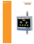
GUCT allows the user to apply and check these pointing offsets (Figure 13). After the
target field coordinates have been entered, the pointing offsets should be entered in the
fields “Offset RA” and “Offset Dec”. Upon clicking ‘Point telescope/Update View’, the
Aladin sky view will show the HAWK-I FoV at the end of the acquisition, i.e. with the
pointing offsets applied. Note that the offsets are in sky coordinates and in arcseconds
(same as in the HAWK-I acquisition template).
GUCT sends these target offset parameters to P2PP when the FC is created and
attached to the OB.
Figure 13: Example of HAWK-I pointing offsets. The telescope will perform an offset
of 100 arcsec to the East and 50 arcsec to the North, after its initial pointing to the
coordinates of NGC 2627.
7. Keyboard shortcuts
Here we provide the list of implemented shortcuts, to execute specific commands within
the Guidecam tool. The keyboard modifier is cmd for OS X and CTRL for Linux. These are
either displayed by underlining the first command letter, or by positioning the mouse on
the corresponding tab.
•
F: fetch from P2PP
•
P: point telescope
•
T: move to science target tab
•
G: move to Guide star selection tab
•
R: move to reference star selection tab
•
O: move to offset tab
•
J: move to jitter tab
•
S: save finding chart
Document Classification: ESO Internal
Doc. Number:
Guidecam User Manual
ESO-258369
Doc. Version: 1.1
Released on:
Page:
20 of 22
8. List of keywords passed to P2PP
The Guidecam tool interacts with P2PP and assigns or updates information in the
acquisition template of a given OB. Some information are instrument/mode dependent,
some others are generic.
The following information assigned or updated to a selected OB are generic:
OB-level parameters
Parameter
Value
OB name
Name as input by user for FC
generation
Target Right Ascension
Target Declination
generic acquisition template parameters
Parameter
Value
TEL.AG.GUIDESTAR
‘SETUPFILE’
TEL.GS1.ALPHA
right ascension of 1 guide star
TEL.GS1.DELTA
declination of 1 guide star
st
st
In the following, instrument/mode dependent information are provided.
8.1 VIMOS
VIMOS specific acquisition template parameters for IMG, PRE
Parameter
Value
TEL.GS1.PPOS
Guide probe position:[POS | NEG]
TEL.ROT.OFFANGLE
Rotator angle on sky
VIMOS specific acquisition template parameters for IFU
Parameter
TEL.ROT.OFFANGLE
Value
Rotator angle on sky
Document Classification: ESO Internal
Doc. Number:
Guidecam User Manual
Released on:
Page:
8.2 VISIR
VISIR specific acquisition template parameters for IMG
Parameter
TEL.ROT.OFFANGLE
Value
Rotator angle on sky
8.3 HAWK-I
HAWK-I specific acquisition template parameters for non-AOF and
AOF-TTS-free
Parameter
Value
TEL.TARG.OFFSETALPHA
Offset in RA in arcsec
TEL.TARG.OFFSETDELTA
Offset in Dec in arcsec
TEL.ROT.OFFANGLE
Rotator angle on sky
HAWK-I specific acquisition template parameters for AOF
Parameter
Value
TEL.GS2.ALPHA
guide probe backup RA coordinate
TEL.GS2.DELTA
guide probe backup DEC coordinate
TEL.TTS1.ALPHA
RA of the TT star 1
TEL.TTS1.DELTA
DEC of the TT star 1
TEL.TTS2.ALPHA
RA of the TT star 2
TEL.TTS2.DELTA
DEC of the TT star 2
TEL.ROT1.OFFANGLE
Position Angle on Sky (deg) w.r.t. TTS1
TEL.ROT2.OFFANGLE
Position Angle on Sky (deg) w.r.t. TTS2
TEL.TARG.OFFSETALPHA1
Alpha offset for target (") w.r.t. TTS1
TEL.TARG.OFFSETDELTA1
Delta offset for target (") w.r.t. TTS1
TEL.TARG.OFFSETALPHA2
Alpha offset for target (") w.r.t. TTS2
TEL.TARG.OFFSETDELTA2
Delta offset for target (") w.r.t. TTS2
TEL.TTS1.RMAG
R mag of the TT star 1
Document Classification: ESO Internal
ESO-258369
Doc. Version: 1.1
21 of 22
Doc. Number:
Guidecam User Manual
Released on:
Page:
TEL.TTS1.RCOLOR
R-I color of the TT star 1
TEL.TTS1.RADPOS
Radial position TTS1 arm (")
TEL.TTS2.RMAG
R mag of the TT star 2
TEL.TTS2.RCOLOR
R-I color of the TT star 2
TEL.TTS2.RADPOS
Radial position TTS2 arm (")
--- End of document ---
Document Classification: ESO Internal
ESO-258369
Doc. Version: 1.1
22 of 22