1
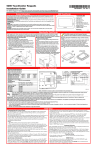
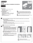
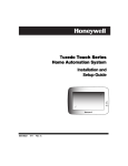
NOTE: Visit www.MyWebTech.Honeywell.com for the full "Installation and Setup Guide."
VAM (VISTA Automation Module) - Installation & Setup Guide
VAM Features:
Introduction
VISTA Automation Module (herein referred to as “VAM”) combines home automation and home
security. The VAM’s features allow integration with VISTA installations to support Z-Wave devices;
is intended for use with compatible VISTA® series controls.
The VISTA Automation Module also supports Remote Services for controlling Z-Wave devices and
Scenes remotely from an associated Total Connect™ account or port forwarding option.
VAM is controlled using a web browser on a Wi-Fi enabled smart device such as a Tablet PC, laptop,
Smartphone, etc.
Built in Web Server
Wi-Fi and LAN Connectivity
Z-Wave® Technology
Honeywell Total Connect Remote
Services Compatible
• Supports up to 32 IP Cameras (4
viewable at one time)
•
•
•
•
DISPLAY NOTE: For optimum viewing of the screens and menus, the tablet’s font size setting may need to be adjusted.
Make Wiring Connections
The VAM connects to the control’s keypad data (ECP) terminals
using the provided 4-wire keypad harness.
Verify that VAM and other connected devices do not exceed the
control’s Aux Power output capability. If it does, use a supplementary
power supply as shown.
IMPORTANT: When VAM is
powered from an auxiliary
power supply, always apply
power to the control panel
first and then VAM. Failure
to observe this sequence
results in improper
operation of VAM and may
result in an ECP Error
indication.
Wire Connections to the Control Panel
Supplementary Power Connections
Mount the VAM
VAM is for indoor use only and should be mounted near the
control or a keypad connected to the control for ease of wiring.
NOTE: If using Z-Wave devices, the best practice is to enroll a
device (see Adding Z-Wave Device Section) and position the VAM
in centralized location to confirm best Z-Wave reception.
VAM mounts to a wall surface by hanging on two screws. See the
diagram to the right.
• Leave the screw heads 1/8” above the wall surface.
• If necessary, drill a hole in the wall for the wire harness to pass
through.
• Connect the wire harness to the VAM before mounting.
Refer to control’s installation instructions for correct data
(ECP) terminal connections.
Mounting Diagram
Insert an SD/SDHC Memory Card
When inserting the gold contacts on the card must face you.
NOTES:
• Avoid touching the contacts on the card
• 4GB SD card supplied
• Supports up to 16GB SD/SDHC Card
See “Software Upgrades” section for details on automatic updates.
Front Panel LEDs
LED
Power Status
(Green)
FUNCTION
Indicates power status.
• Blinking when it is powered up and
booting.
• Solid green when it is fully functional.
Network Status Indicates Wi-Fi Status.
(Blue)
• In normal operation the LED blinks when
VAM is booting
• Solid blue when VAM is ready as AP
mode (acting as an Access Point) or
connects to the internet as station mode
(STA mode). STA mode is when the
VAM is connected to the Wi-Fi router
only, internet access may be available,
but the VAM disables all remote access.
Operation
In normal operation, the LED is normally off.
Status (Yellow) • It will blink slowly when there is no ECP
(including ECP error) or Z-wave
controller not responding.
• Fast blinking indicates Z-wave is in
enrollment or deletion status.
Reset Button
Press to reboot the device.
Wi-Fi &
• Wi-Fi Network Reset: Press and hold
Factory Default
down for more than 5 seconds to clear
Button
the VAM’s Wi-Fi network connection.
You then need to reconnect the VAM to
your Wi-Fi network.
• Factory Default Reset: Double press
this button, then, while the green, blue,
and yellow LEDs blink in sequence,
press and hold down this button for more
than 5 seconds to set the VAM to its
factory default settings.
Specifications
Width: 7.58’’ (192.5mm)
Height: 5.31’’(135.0mm)
Depth: 0.53’’(13.45mm)
Voltage: 12VDC
Current: 180mA
Humidity : 93% RH, non-condensing
Temperature:
• Operating : 14˚F to 131˚F / -10˚C to 55˚C
• Shipping / Storage: -40˚F to 158˚F / -40˚C to 70˚C
Program the Control Panel for use with VAM
At the control, assign an appropriate touch screen (AUI) type device
address (ECP address) for VAM, and set a partition (if applicable).
• Refer to the control’s programming instructions for detailed
procedures.
NOTE: Do not use VAM’s Console Mode to program the control.
• After enabling the VAM device address in the control, set the VAM to the selected address. See the “Program Device’s ECP Address”
section.
NOTE: The default address in the VAM is 1.
• Changing the VAM’s ECP address after initial installation will cause a reboot, during this process the VAM will be inaccessible.
On VISTA® Plus series or equivalent
Use data field *189 to enable an unused device address 1, 2, 5 or 6 for the VAM. Addresses 1 and 2 are enabled by default.
On VISTA® Turbo and Commercial VISTA Series (VISTA-128BP, 128BPT, VISTA-128FBP, 128FBPT, etc.)
Use #93 Menu mode to enable an unused device address.
• For older controls under Rev. 10, addresses 1-2, and 3-30 may be used.
• For VISTA Turbo series controls Rev. 10 and higher, addresses 1-30 may be used. These addresses are normally not defaulted for AUI
type devices.
If using Remote Services
Enable an appropriate RIS address in the control and verify the option is enable the in the control’s programming.
• On VISTA Plus Series panels below revision 10, the second digit of field *91 must be enabled with a 2. On panels with revision 10 or
higher, the RIS option is automatic and not necessary to enable.
• On VISTA Turbo Series controls, choose the device address to set to RIS and enter a device type of 12.
NOTES:
• These options MUST match how the AlarmNet Communicator is programmed.
• Z-Wave scene programming requires RIS enabled, to assign different triggers and actions.
Quick Arming Options
In PC or Mobile View, when user presses arm Away/Night/Stay they will be prompted to enter a user code. If “Quick Arming” is
enabled a user code is not required. Refer to the control’s installation instructions for enabling the Quick Arm feature.
2
Initial Setup
The initial set up of the VAM is performed in 3 steps.
1. Choose the Language
2. Connect to the Wi-Fi network
3. Collect user data and giving the VAM a name
Language Settings
Upon power up, the first option is to select a language (This also occurs after a factory defaulting the unit.)
NOTE: This can also be changed later by accessing pressing Setup > Language. The VAM can display one of 4 languages: English
(default), Español, Português, Français.
Once you have selected the language press Save at the bottom of the page, or Next.
Wi-Fi network Configuration
To set up the Wi-Fi network for the VAM, the following is needed:
Wi-Fi enabled smart device (Tablet PC, laptop, Smartphone, etc.)
VAM SSID and WPA2 password (located on the VAM’s label)
VAM default IP address: 192.168.2.1
Home router SSID and WPA2 password (typically located on the home router’s label); home router must use WPA2 encryption
and have a password (key) assigned.
• The initial configuration for connecting to the VAM and retrieving a local IP address requires internet access to the local area
network (LAN).
•
•
•
•
NOTES:
•
•
•
•
Before setting up the network, set your smart device for Wi-Fi operation only (turn off 3G/4G option).
If the wireless router is later replaced, these steps must be repeated to connect the VAM to the new router.
If SSID is lost, contact technical support at (800) 645-74924.
If AP only mode is desired, press Skip on the bottom of the page to skip the Wi-Fi Setup.
1. Connect a smart device to the VAM.
a.
b.
c.
d.
Power up the VAM.
Connect the smart device’s Wi-Fi to VAM using the device’s Wi-Fi settings menu (VAM is a
wireless access point).
Enter the VAM SSID: VAM_xxxx (SSID is case-sensitive)
NOTE: xxxx = the last 4 digits of the MAC address
Enter the Key (found on the VAM and labelled “WPA2 key”)
2. Connect the VAM to the home router.
a. Open a web browser on the smart device.
b. Enter the VAM’s default IP address: 192.168.2.1 into the browser on your smart device.
c. Enter the home routers SSID and security key (SSID and security key are case-sensitive).
d. press Connect. A 1 minute countdown begins and displays “The device is connecting to “Network
Name”, please keep this page open. Go to Wi-Fi setup and select the “Network Name” access
point and return to this page.” During this time, a new network IP address is assigned to the
VAM.
Note: If you have trouble connecting, please follow the onscreen instructions and retry the connection
process. If using DHCP option, confirm the router is connected to the internet. If using Static IP
option, verify an IP address is available.
e. When completed, the VAM connects to the assigned router and displays the “User Data Screen”.
3. User Data Screen
This page collects the user’s data. Enter the data or press Skip to continue to the VAMs home
page.
Name
Region
Zip Code
Device Name
Mobile Number
E-mail ID
NOTES:
•
•
•
•
This page can be accessed from the home page by pressing Setup > User Profile
The data for Region and Zip Code/Postal Code synchronizes to the Time/Date setup page if completed during the initial
setup.
The e-mail address synchronizes to the e-mail setup page, if completed during the initial setup.
The Zip Code option is needed for the sunset/sunrise for Z-Wave scenes.
3
End User License Agreement (EULA)
The end user license displays and gives you the option to skip or accept the EULA. Choose the option to display the home page.
NOTE: This option reappears during initial installation or after a factory default of the unit.
Program the VAM Device Address
Default VAM device address = 1.
1. Press Setup > System.
2. Press ECP Address. Using the Up/Dn arrows, choose the device address assigned for VAM in the control panel.
3. Press Apply.
4. The VAM automatically reboots after the device address is set.
Note: The Primary RIS option is only selected if the customer is NOT using Total Connect remote services. Enabling can cause
unpredictable results.
Set the Time & Date
Get Time/Date from the Control Panels
Press Setup > System > Time/Date Setup > Verify the time is set in the control panel > Get Time.
Note: Some older Commercial panels do not support the get time feature.
Set Up Email Notification
Users (and/or the installer) can receive email notifications when one or more selected system events or conditions occur.
NOTE: Email notification requires that the user has an active email address and note the disclaimer at the bottom of the page.
“Email notification is strictly for convenience use only. Avoid relying on this feature for life critical events. It is not UL
certified and may fail at any time without notice.”
1. Press Setup > E-Mail.
2. Press User SMTP to select the email provider. SMTP
Event
Description
establishes the email server’s domain (the “from”
Security
Disarm, Away Secured (End of Exit), Arm
address).
Stay
a. From the drop-down menu, select the email
Zones
Alarm, Trouble, Restore
provider (Gmail, Outlook, Yahoo), or Add New.
Thermostat
Temperature Above and Below
b. Enter the email ID (user name) and password.
Door Lock
Locked, Unlocked
c. The Email Server and SMTP port number fields
Garage Door Closed, Opened, Operation Disabled/Failed
are automatically populated unless “Add New”
Water Valve
Closed, Opened
was selected.
d. If Add New was selected, enter the appropriate SMTP and port number information (see your email provider for details).
e. Press Save.
3. Select the email addresses that will be notified when event types and conditions occur.
a. Press Event 1 to define the event types and conditions that will trigger notifications to the chosen email address(es).
b. There are 4 events. Each event will allow you to send to 4 separate emails. Choices for email notification options include
Security, Zone, Thermostat, Door Lock, Garage Door, and Water Valve.
c. Press Save and you will get a response that says “Notification Save Success.”
4. Repeat step 3 for Events 2-4, if desired.
Troubleshooting
If an error is returned through the listed SMTP email provider stating that the email has blocked a sign in attempt, return to the
SMTP server page and verify the email settings. The VAM displays “Warning: Email sending failed. Please check SMTP settings.”
If this is the case, check the security settings for the email chosen through the provider.
Adding Z-Wave Devices
EXISTING NETWORK NOTE: Z-Wave products from other manufacturers can be included (added) into the VAM
network. Z-Wave devices that are always powered can serve as repeaters regardless of manufacturer.
To add (include) Z-Wave devices, verify the device is properly installed, log onto home screen, then do the following:
1. Press Automation > Z-Wave Setup > Add Device.
2. Press the Function Key on the device; follow the on-screen messages until “Device added successfully.”
NOTE: Refer to the manufacturer’s instructions for proper installation procedures.
Do not use any garage door automation with any garage door opener that lacks the safety features required by U.S. federal
safety standards (this includes any garage door opener model manufactured before January 1, 1993). A garage door opener
that cannot detect an object and stop and reverse the door – does not meet current U.S. federal safety standards. Your
garage door opener also must signal before unattended door operation. For more information please consult your garage
door opener manual.
4
Defaulting the Z-Wave Controller
To remove all Z-Wave devices, do the following:
1. Press Automation > Z-Wave Setup to display the “Z-Wave
Device Management” screen.
2. Press Z-Wave Default to delete all devices from the controller.
3. Select Yes. The following message is displayed:
This Z-WAVE controller is about to be factory defaulted and will
lose all devices in the enrolled list.
All Z-WAVE devices must be re-enrolled after this reset.
Each device will have to be excluded before it can be reenrolled.
Yes or No
NOTE IF SYSTEM DEFAULT IS PERFORMED: If VAM
is reset to Factory Defaults the controller will assign a
new network ID. All Z-Wave devices must be re-included
into the system, even if they appear on the Device List.
Remove all Z-Wave devices first, then re-include all
desired devices (see Adding Z-Wave Devices section).
Changing Z-Wave Device Names and Icons
To change the icons, do the following:
1. Press Automation > Z-Wave Setup to display the “Z-Wave Device Management” screen.
2. Press Z-Wave device to be edited.
3. Choose the icon to represent the device.
NOTE: This applies to Binary and Multilevel switches only.
Light Bulb
Light Switch
Garage Door
Sprinkler
Pool
Water Faucet
Strobe
Window
Siren/Sounder
Fan
Using VAM as a Secondary Controller
VAM can be used as a secondary controller when connected to another Z-Wave network.
NOTE: If VAM is configured as secondary controller, it cannot be used with Total Connect Remote Services.
1. Remove any Z-Wave devices previously included in the VAM.
2. Press Automation > Z-Wave Setup to display the Z–Wave Management screen, press Z-Wave Default and press Yes.
3. Press the Z-Wave Primary icon to switch the VAM to a secondary controller. The Z-Wave Primary icon changes to Z-Wave
Secondary accordingly.
4. Start the inclusion process at the other network’s primary controller (see controller’s manual), then press the Add Device icon in the
VAM’s Z-Wave Management screen. To remove (exclude) VAM from the primary controller, start the exclusion process at the
primary controller, then press the Remove Device button in VAM.
NOTES:
• Some manufacturers have software that can configure the network. If this is the case, after all devices are enrolled in the network,
you must learn in the VAM as a secondary controller to “import” all the devices over to the VAM. Once this is complete, you can
switch roles to primary. This is done by accessing the “role shift” option on the primary controller and on the VAM by pressing
Setup > System > Z-Wave advanced Setup > Z-Wave Secondary Controller Shift to Primary.
When VAM is configured as secondary it cannot be used with Total Connect 2.0.
Integrating Total Connect
1. Pressing the Diagnostic Connect icon in the bottom left corner will test the AlarmNet server’s connection status. If the test has
failed, check your network connection
2. Verifies the Z-Wave status, if enabled it will communicate Z-Wave status to Total Connect 2.0.
Pressing the “TC” icon will populate a list of all your Z-Wave devices with an enable or disable option. This enables or
disables those chosen devices from appearing on the Total Connect 2.0 account.
5
Compatible Z-Wave Devices
Z-Wave devices may vary; follow the instructions in the online Installation Guide or User Guide provided for installation steps.
Door Locks
Yale® Real Living Push Button Lever/Deadbolt Lock
Appliances
HomeManageable Appliance Module
Intermatic® Wayne Dalton Small Home Settings
Small Appliance Module (HM-AM001)
GE® Wireless Lighting Control Plug In Appliance
Module
Yale® Real Living Touchscreen Lever Lock (YRL220)
Yale® Real Living Touchscreen Deadbolt lock (YRD220)
Schlage® Link Deadbolt Lock (BE369)
Schlage® Link Lever Lock (FE599)
Schlage Touchscreen Deadbolt (BE468/BE469/BE469NX)
Kwikset® Smartcode Lever lock (912)
Kwikset Smartcode Deadbolt Lock (910TRL/910CNT/914TRL)
Lights
Leviton®/ViziaRF+ Switches (VRPA2-1LW)
Leviton®/ViziaRF+ Dimmers (VRPD3-1LW)
Leviton® /ViziaRF+ Plug in Modules (ZRP15)
GE®
Wireless
Lighting
Control
Dimmers
(45602/ZW4101)
GE®(Wireless
Lighting
Control
Switches
(45602/ZW3101)
GE Wireless Lighting Control Plug in Lamp
Modules
Wayne Dalton HomeSettings Lamp Module HA03)
Kwikset Smartcode Touchscreen Lock (916TRL)
Thermostats
Honeywell® Z-Wave Thermostat (ZWStat)
Wayne Dalton® Zwave thermostat
Trane® Zwave Thermostat
(TZMT400AB32MAA/TZMT400BB32MAA)
Garage Door Module
Linear® Z-Wave Garage Door Opener Remote
Controller (GDZ00Z-4)
Radio Thermostat® Company of America (CT100/CT32)
Trane® Zwave Thermostat
(TZMT400AB32MAA/TZMT400BB32MAA)
Current Innovations® Touch Screen (CI-300E)
Water Valves
Fortrezz® Wireless Z-Wave Water Valve (WV-01)
NOTE: The listed companies above may manufacturer multiple Z-Wave devices. Installing ‘like’ modules not included on this list may
produce unpredictable results. These devices have not been confirmed to be compatible.
Adding Cameras
The VAM supports up to 32 cameras.
IMPORTANT: Connect cameras only when accessing VAM via the home router network and follow the camera’s instructions for
mounting.
1. To add a camera to VAM, it must be initially connected via an Ethernet cable, even if the camera is wireless. After a wireless camera
is added, the Ethernet cable can be removed.
a. Connect an Ethernet cable to the back of the camera (LAN); connect the opposite end to the Ethernet port on the router.
b. Apply power to the camera; wait for initial power-up.
c. Press Multi-Media > Camera Setup.
d. Press the Discovery button to locate the camera. The screen displays an “in progress” message.
NOTE: For best performance set video resolution to 320 x 240, at 8 frames per second, Normal quality.
• Maximum suggested camera resolution = 640 x 480.
• Maximum suggested frame rate = 15 fps.
e. If the camera information is not discovered automatically, press the Add button to enter camera information manually.
2. To edit camera information, select the camera name and press the Edit button. Enter required information and then press Save.
Manual Camera Setup
1. Connect an Ethernet cable to the back of the camera (LAN); connect the opposite end to the Ethernet port on the router. (NOTE: A
LAN connection is initially required and once configured the Camera WIFI
2. Apply power to the camera; wait for initial power-up.
3. press Multi-Media > Camera Setup.
4. Enter the camera details below:
Camera Name
Camera IP Address or URL
MJPEG Streaming URL
RTSP (Real Time Streaming Protocol) Port #
Resolution (Options are 160x120, 320x240, 640x480)
will change from a LAN to Wi-Fi.)
Camera Model
RTSP Streaming URL
Mobile Streaming URL
HTTP Port
Frame Rate (Ranges from 1-30 Frames Per Second)
NOTES:
• In general, VAM is designed to support cameras with the following features: UPnP for camera discovery on LAN, RTSP streaming,
MPEG4, H.264, and Onvif for streaming on the VAM, MJPEG for streaming to browsers.
6
NOTE: Every camera manufacturer makes their cameras slightly different, so it is not a guarantee that VAM will work with
every camera that supports the above network and codec features.
• Maximum number of enrolled cameras cannot exceed 32, with only 4 viewable at any one time.
NOTE: If using Total Connect 2.0 remote services, only Honeywell AlarmNet IP cameras (with a maximum of 6) have the capability
to be viewed from the customers remote service account. Settings are defaulted for Honeywell AlarmNet IP Cameras, changing the
model Number will not automatically adjust to the cameras correct settings. Refer to the cameras setup utility to gather this
information.
Software Upgrades
System Information
To view the current software version installed on your system, do the following: Press Setup > System Info.
Automatic Software Updates
To receive automatic remote updates an SD card with a minimum of 200mb available space is required. When an update is available,
the system will automatically update the system.
NOTES:
1. After a software upgrade, it is recommended that you delete your browser’s Temporary Internet Files (cache). Undesired operation
may occur if these files are not deleted.
2. Upon next login to the VAM, an End User License Agreement (EULA) will be prompted. Press Accept, then proceed to using the
VAM as normal.
•
Options
IMPORTANT: This menu is intended for the installer only and should not be changed by the user. See the “Full Installation and Setup
Guide” for more information.
Set Up Remote Access (Account Setup)
Remote access lets the user access the VAM’s menus directly via the Internet when away from home. The home router must first be
configured for port forwarding. Refer to the router’s instructions for details on port forwarding.
NOTE: When using VAM via remote access, the System HTTP API link will not display.
To set up a remote access log in, do the following:
1. Press Setup > Account.
2. Enter the desired user name and password. Passwords must be a minimum of 8 alphanumeric characters, and must include at least
one uppercase, one lowercase, and one number.
3. “Enable local access authentication” will prompt the user to enter a user name and password. This allows them to gain access to the
VAM, when connecting using the local IP address.
NOTE: If the user forgets the password (or one does not exist) they can always locally access the VAM within 20 minutes of
power up.
4. Press Save. The new user is displayed. (To clear a user’s login, Press the CLEAR icon.)
NOTES:
• Remote login is blocked after 3 failed attempts. To reset remote access, you must connect to VAM locally via the home router; then
re-enable remote access. Press Setup > Account, then press the appropriate user Enable icon and press Save.
• Port 443 is the fixed port assigned to the VAM and cannot be changed. It is a secure login procedure, the URL must begin with
HTTPS:// then the external IP address. If not, you may receive an error of “There is a problem with this devices security certificate.”
• For an external dynamically assigned IP address, using a DYNDNS can prevent troubles logging in due to the external IP address
changing. Refer to the DYNDNS provider for set up instructions.
7
FEDERAL COMMUNICATIONS COMMISSION (FCC) AND INDUSTRY CANADA (IC) STATEMENTS
The user shall not make any changes or modifications to the equipment unless authorized by the Installation Instructions or User's Manual. Unauthorized
changes or modifications could void the user's authority to operate the equipment.
CLASS B DIGITAL DEVICE STATEMENT
This equipment has been tested to FCC requirements and has been found acceptable for use. The FCC requires the following statement for your information:
This equipment generates and uses radio frequency energy and if not installed and used properly, that is, in strict accordance with the manufacturer's
instructions, may cause interference to radio and television reception. It has been type tested and found to comply with the limits for a Class B computing
device in accordance with the specifications in Part 15 of FCC Rules, which are designed to provide reasonable protection against such interference in a
residential installation. However, there is no guarantee that interference will not occur in a particular installation. If this equipment does cause interference to
radio or television reception, which can be determined by turning the equipment off and on, the user is encouraged to try to correct the interference by one or
more of the following measures:
• If using an indoor antenna, have a quality outdoor antenna installed.
• Reorient the receiving antenna until interference is reduced or eliminated.
• Move the radio or television receiver away from the receiver/control.
• Move the antenna leads away from any wire runs to the receiver/control.
• Plug the receiver/control into a different outlet so that it and the radio or television receiver are on different branch circuits.
• Consult the dealer or an experienced radio/TV technician for help.
Industry Canada Class B Statement
This Class B digital apparatus complies with Canadian ICES-003.
Cet Appareil numérique de la classe B est conforme à la norme NMB-003 du Canada.
FEDERAL COMMUNICATIONS COMMISSION (FCC) PART 15
This device complies with Part 15 of the FCC Rules and RSS-210 of Industry Canada. Operation is subject to the following two conditions: (1) This device may
not cause harmful interference, and (2) this device must accept any interference received, including interference that may cause undesired operation.
Cet appareil est conforme à la partie 15 des règles de la FCC & de RSS-210 des Industries Canada. Son fonctionnement est soumis aux conditions suivantes:
(1) Cet appareil ne doit pas causer d' interférences nuisibles. (2) Cet appareil doit accepter toute interférence reçue y compris les interférences causant une
réception indésirable.
RF EXPOSURE WARNING
The VISTA Automation Module (VAM) must be installed to provide a separation distance of at least 7.8 in. (20 cm) from all persons and must not be
co-located or operating in conjunction with any other antenna or transmitter except in accordance with FCC multi-transmitter product procedures.
Mise en Garde
Exposition aux Fréquences Radio: L'antenne (s) utilisée pour cet émetteur doit être installée à une distance de séparation d'au moins 7,8 pouces (20
cm) de toutes les personnes.
Z-Wave® devices are identified by the Z-Wave logo and
can be purchased from your local retailer.
Z-Wave® is a registered trademark Sigma Designs, Inc.
and/or its subsidiaries.
SUPPORT & WARRANTY
For the latest documentation and online support information, please go to:
https://mywebtech.honeywell.com
For the latest warranty information, please go to:
www.honeywell.com/security/hsc/resources/wa.
Ê800-15858V2*Š
800-15858V2 3/15 Rev. B
MyWebTech
Warranty
2 Corporate Center Drive, Suite 100
P.O. Box 9040, Melville, NY 11747
Copyright © 2014 Honeywell International Inc.