1
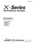
SWITCH MODE
INDUSTRIAL BATTERY CHARGER
USER’S MANUAL
Important Safety,
Installation,
Operation, and
Maintenance
Instructions
www.LesterElectrical.com
Summit Series
2 of 20
User’s Manual
CHARGER RATINGS LABEL
The ratings label is located on the back of the charger. The label provides the model (MODEL), part number
(PART NO), serial number (SERIAL NO), AC input ratings (INPUT), and DC output ratings (OUTPUT, CELLS,
and AH) of the charger. The amp-hour (AH) rating indicates the full range of battery capacities that are
recommended for use with this charger. Different battery profiles may be required to optimize the charging of
specific battery capacities within this range. The BATTERY field indicates the factory-configured battery profile.
An example charger ratings label is provided below.
Please fill in the blank label that is provided below with the information from the ratings label on your charger for
future reference.
Document any configuration or settings changes that are made by marking the ratings label on your charger or on
an additional label or tag attached to your charger.
SAVE THIS MANUAL: Keep it in a location where it is available to anyone who may
operate the charger.
Summit Series
3 of 20
User’s Manual
TABLE OF CONTENTS
CHARGER RATINGS LABEL ...................................................................................................3
TABLE OF CONTENTS .............................................................................................................4
IMPORTANT SAFETY INSTRUCTIONS ...................................................................................5
1. INTRODUCTION ...................................................................................................................7
2. RECEIVING AND INSTALLING THE CHARGER.................................................................7
3. BATTERY TYPE ...................................................................................................................9
4. OFF-BOARD (SHELF) VERSUS ON-BOARD (BUILT-IN) CHARGERS..............................9
4.1 Off-Board Chargers ..................................................................................................................................9
4.2 On-Board Chargers ..................................................................................................................................9
5. AC INPUT ............................................................................................................................ 10
6 DC OUTPUT ......................................................................................................................... 10
7 VEHICLE LOCKOUT CONTROL (OPTIONAL) ................................................................... 11
8 BATTERY TEMPERATURE SENSOR (OPTIONAL)........................................................... 11
9. PROPER CARE OF DEEP-CYCLE LEAD-ACID MOTIVE POWER BATTERIES ............. 12
9.1 Personal Safety Precautions ................................................................................................................ 12
10. CHARGER OPERATION .................................................................................................. 13
10.1 Off-Board Charger Operation ............................................................................................................. 13
10.2 On-Board Charger Operation ............................................................................................................. 14
11. LED INDICATORS ............................................................................................................ 15
12. FAULTS ............................................................................................................................ 16
13. TROUBLESHOOTING ...................................................................................................... 17
14. SPECIFICATIONS............................................................................................................. 18
Summit Series
4 of 20
User’s Manual
IMPORTANT SAFETY INSTRUCTIONS
1.
SAVE THESE INSTRUCTIONS – This manual contains important safety and operating instructions.
2.
Before using battery charger, read all instructions and cautionary markings on battery charger,
battery, and product using battery.
LOOK FOR THIS SYMBOL TO POINT OUT SAFETY PRECAUTIONS.
IT MEANS: BE ALERT—YOUR SAFETY IS INVOLVED. IF YOU DO
NOT FOLLOW THESE SAFETY INSTRUCTIONS, INJURY OR
PROPERTY DAMAGE CAN OCCUR.
3.
4.
DANGER: TO REDUCE THE RISK OF FIRE OR ELECTRIC SHOCK, CAREFULLY READ AND
FOLLOW THESE IMPORTANT SAFETY AND OPERATING INSTRUCTIONS BEFORE INSTALLING
OR OPERATING THE CHARGER.
INSTRUCTIONS IMPORTANTES CONCERNANT LA SECURITÉ.
5.
WARNING: TO REDUCE THE RISK OF FIRE, INSTALL THIS BATTERY CHARGER ON A
SURFACE OF NON-COMBUSTIBLE MATERIAL SUCH AS BRICK, CONCRETE, OR METAL.
6.
DANGER: RISK OF ELECTRIC SHOCK. DISCONNECT CHARGER FROM BATTERY AND AC
POWER BEFORE SERVICING. TURNING OFF THE CHARGER DOES NOT REDUCE THIS RISK.
7.
DANGER: RISK OF ELECTRIC SHOCK. DO NOT TOUCH UNINSULATED PORTION OF AC OR
DC CONNECTORS OR UNINSULATED BATTERY TERMINAL.
8.
DANGER: RISQUE DE CHOCKS ÉLECTRIQUES. NE PAS TOUCHER LES PARTIES NON
ISOLÉES DU CONNECTEUR DE SORTI OU LES BORNES NON ISOLÉES DE L’ACCUMULATEUR.
9.
CAUTION: CHARGE ONLY BATTERIES OF THE SAME TYPE, VOLTAGE, CELL NUMBER, AND
AMP-HOUR CAPACITIES AS SHOWN ON THE LABEL. OTHER TYPES OF BATTERIES MAY
BURST CAUSING PERSONAL INJURY AND DAMAGE. BEFORE CHARGING ANY OTHER TYPE OF
RECHARGEABLE BATTERY, CHANGE THE CHARGER SETTINGS AS RECOMMENDED BY THAT
BATTERY MANUFACTURER.
10.
ATTENTION: UTILISER POUR CHARGER UNIQUEMENT LES ACCUMULATEURS AU PLOMB À
ELECTROLYTE LIQUIDE. D’AUTRES TYPES D’ACCUMULATEURS POURRAIENT ÉCLATER ET
CAUSER DES.
11.
DANGER:
TO PREVENT ELECTRICAL SHOCK, DO NOT TOUCH EITHER AC OR DC
UNINSULATED PARTS. MAKE SURE ALL ELECTRICAL CONNECTORS ARE IN GOOD WORKING
CONDITION. DO NOT USE CONNECTORS THAT ARE CRACKED, CORRODED OR DO NOT MAKE
ADEQUATE ELECTRICAL CONTACT. USE OF A DAMAGED OR DEFECTIVE CONNECTOR MAY
RESULT IN A RISK OF OVERHEATING OR ELECTRIC SHOCK.
12.
13.
WARNING: HAZARD OF ELECTRIC SHOCK.
WARNING: LEAD-ACID BATTERIES GENERATE EXPLOSIVE GASES. TO PREVENT ARCING
OR BURNING NEAR BATTERIES, DO NOT DISCONNECT DC CHARGING CORD FROM BATTERIES
Summit Series
5 of 20
User’s Manual
WHEN THE CHARGER IS OPERATING.
AWAY FROM BATTERIES.
KEEP SPARKS, FLAME, AND SMOKING MATERIALS
14.
WARNING: ALWAYS SHIELD EYES WHEN WORKING NEAR BATTERIES. DO NOT PUT
WRENCHES OR OTHER METAL OBJECTS ACROSS BATTERY TERMINAL OR BATTERY TOP.
ARCING OR EXPLOSION OF THE BATTERY CAN RESULT.
15.
WARNING: BATTERIES PRODUCE HYDROGEN GAS, WHICH CAN EXPLODE IF IGNITED.
NEVER SMOKE, USE AN OPEN FLAME, OR CREATE SPARKS NEAR THE BATTERY. VENTILATE
THE AREA WHEN THE BATTERY IS CHARGING IN AN ENCLOSED PLACE.
16.
WARNING: LEAD-ACID BATTERIES CONTAIN SULFURIC ACID, WHICH MAY CAUSE BURNS.
DO NOT GET ACID IN EYES, ON SKIN, OR CLOTHING. IF CONTACT WITH THE EYES OCCURS,
FLUSH IMMEDIATELY WITH CLEAN WATER FOR 15 MINUTES AND OBTAIN MEDICAL
ATTENTION.
17.
WARNING: ONLY A QUALIFIED SERVICE TECHNICIAN SHOULD PROGRAM OR SERVICE
THIS EQUIPMENT.
18.
CAUTION: DO NOT OPERATE THE CHARGER IF IT HAS RECEIVED A SHARP BLOW, BEEN
DROPPED, OR OTHERWISE DAMAGED. HAVE A QUALIFIED SERVICE TECHNICIAN EXAMINE
AND REPAIR AS NEEDED.
19.
WARNING: DO NOT DISASSEMBLE THE CHARGER. HAVE THE CHARGER EXAMINED BY A
QUALIFIED SERVICE TECHNICIAN. INCORRECT RE-ASSEMBLY OF THE CHARGER MAY
RESULT IN AN EXPLOSION, ELECTRIC SHOCK, OR FIRE.
20.
CAUTION: MAKE SURE THE BATTERY SYSTEM HAS THE PROPERLY RATED VOLTAGE,
AMP-HOURS, AND TYPE (“WET”, “AGM”, “GEL”, ETC.) FOR THIS CHARGING SYSTEM.
SAVE THESE INSTRUCTIONS
Summit Series
6 of 20
User’s Manual
1. INTRODUCTION
This switch mode (high frequency) industrial battery charger features advanced charge and termination
algorithms designed to optimize both daily battery capacity and overall battery life. The charger is convection
cooled with no moving parts, sealed, and designed to provide maximum reliability. The universal AC input
enables the charger to be used with a wide range of AC voltages and frequencies, and the charger includes
high efficiency and power factor.
The charger was factory-configured with a battery profile intended for use with batteries of the same type,
voltage, and number of cells as is listed on the ratings label (see the Charger Ratings Label section for
additional details). The charger was also factory-configured for on-board or off-board use. Contact your
dealer if you require a different configuration.
2. RECEIVING AND INSTALLING THE CHARGER
WARNING: DO NOT INSTALL THE CHARGER ON OR NEAR FLAMMABLE MATERIALS. POSITION
THE CHARGER ON A FOUNDATION OF STONE, BRICK, CONCRETE OR GROUNDED METAL.
WARNING: CHARGERS CAN IGNITE FLAMMABLE MATERIALS AND VAPORS. DO NOT USE NEAR
FUELS, GRAIN DUST, SOLVENTS, THINNERS, OR OTHER FLAMMABLES.
WARNING: REPLACE WORN, DAMAGED, OR CUT ELECTRICAL CORDS AND PLUGS
IMMEDIATELY.
Unpack the charger and examine it for shipping damage. In the event that shipping damage is found, report it
as a claim with the freight company.
Do not operate the charger with a damaged AC or DC cable or connector. Do not operate the charger if it has
received a sharp blow, was dropped, or was otherwise damaged in any way. Contact your dealer.
Proper installation is important to achieve optimum performance and life from the charger and batteries.
Allow as much free air space around the charger as possible. Please refer to the Specifications section for
specific storage and operating environmental specifications.
The charger was factory-configured for mounting on-board a battery-powered vehicle/machine or off-board
use in a shelf or portable application. Contact your dealer if you desire to use the charger in a non-factoryconfigured manner.
The most favorable orientations of the charger are shown in Figure 2-1.
For on-board use, the most favorable way to mount the charger is with the charger base bolted to a metal
plate (0.1 inch minimum). This provides both a strong structural mounting and good thermal conductive
cooling (examples are shown in Figure 2-1, Views A and B). A poor thermal conductive mounting material
such as plastic or wood would be less favorable for cooling.
The charger dimensions and mounting slot locations are shown in Figure 2-2. For off-board use, optional
handles are available for ease in carrying.
Summit Series
7 of 20
User’s Manual
Figure 2-1: Charger Mounting Recommendations
Figure 2-2: Charger Dimensions and Mounting Slot Locations
Summit Series
8 of 20
User’s Manual
3. BATTERY TYPE
This charger was factory-configured to charge the type of battery indicated in the BATTERY field on the
th
th
charger ratings label (for example, “Wet”). The 13 and 14 characters in the charger part number, available
in the PART NO field on the charger ratings label, provide the battery profile code for the primary battery
profile. For example, charger part number 27790G05K5B1W1 has a primary battery profile code of “W1”
and charger part number 27790G05K5B1A1 has a primary battery profile code of “A1”. Figure 3-1 lists
standard battery profile codes and their corresponding battery profiles. If the battery profile code for your
charger is not listed in Figure 3-1, please contact your dealer for information. To change the active battery
profile for this charger, please contact your dealer. If the active battery profile is changed, mark the charger
ratings label or add an additional label or tag.
CAUTION: THIS CHARGER IS FOR USE ONLY WITH BATTERY SYSTEMS OF THE SAME TYPE AS
THE ACTIVE BATTERY PROFILE. BATTERIES IMPROPERLY MATCHED WITH THE CHARGER MAY
BURST CAUSING PERSONAL INJURY AND DAMAGE TO THE BATTERIES OR CHARGER.
Part Number Battery Profile Code
Battery Profile
W1
W4
A1
G1
Wet, standard
Wet, higher capacity
AGM, standard
Gel, standard
Figure 3-1: Standard Battery Profile Codes and Their Corresponding Battery Profiles
Battery manufacturers frequently use the same battery cases for different battery types. Wet/flooded
batteries have removable cell caps. Water electrolyzed by discharging and charging the battery is replaced
through these openings. Sealed batteries are generally distinguished by non-removable cell caps. The
physical appearance of the battery case is frequently the same as a wet battery, though the cell caps are
generally not removable. Refer to the battery manufacturer's information panel on the battery case to
determine the type battery you have. If the information panel is missing or not legible, do not use the battery.
4. OFF-BOARD (SHELF) VERSUS ON-BOARD (BUILT-IN) CHARGERS
4.1 Off-Board Chargers
Off-board chargers are designed to be used in shelf or portable applications. If the AC input plug is
connected to AC power, a new charge cycle automatically starts when the DC output is connected to a
battery pack of the proper voltage. Disconnecting and reconnecting AC power while the DC output remains
connected to a battery pack WILL NOT automatically start a new charge cycle. Disconnecting the DC output
from the battery pack IS REQUIRED to automatically start a new charge cycle.
4.2 On-Board Chargers
On-board chargers are designed to be mounted on electric vehicles/equipment. If the DC output is connected
to a battery pack of the proper voltage, a charge cycle automatically starts when the AC input plug is
connected to AC power (unless a safety period of time has not passed since the successful completion of the
previous charge cycle). Disconnecting the DC output from the battery pack is NOT REQUIRED to
automatically start a new charge cycle.
Summit Series
9 of 20
User’s Manual
5. AC INPUT
The charger has an AC input rating of 100-230 volts, 50-60 hertz, single-phase. The charger has an AC
operating range of 90-264 volts, 45-65 hertz. Below 100 volts, the charger may reduce output power.
The charger is equipped with an IEC inlet for the AC input power. This allows the AC power cord to be
selected with a proper plug to be compatible with the local wall outlets. An optional AC cord clamp is available
to retain the AC power cord.
The charger must be grounded to reduce the risk of electric shock and is equipped with an IEC inlet having an
equipment-grounding conductor and a grounding socket. The installed AC power cord must be plugged into
an outlet that is properly installed and grounded in accordance with all applicable electrical codes and
ordinances.
If this charger includes the UL Listed symbol on its ratings label, it is provided with a cord set for connection to
outlets operating at nominal 120 volts (or 240 volts as appropriate). If the input plug does not fit the power
outlet, contact Lester Electrical for the proper cord set terminating in an attachment plug of the proper
configuration for the power outlet.
CAUTION: TO REDUCE THE RISK OF ELECTRIC SHOCK OR FIRE, DISCONNECT AC POWER
FROM THE CHARGER BEFORE INSTALLING OR REMOVING UNIT.
DANGER: NEVER ALTER THE AC POWER CORD OR PLUG PROVIDED. IF IT WILL NOT FIT AN
OUTLET, OBTAIN THE CORRECT CHARGER IEC AC CORDSET FOR THE OUTLET, OR HAVE A
PROPER OUTLET INSTALLED BY A QUALIFIED ELECTRICIAN. IMPROPER CONNECTION CAN
RESULT IN A RISK OF ELECTRIC SHOCK.
If an extension cord is necessary, it must be a 3-conductor, No. 12 AWG minimum, heavy-duty cord with
ground. It must also be in good electrical condition and as short as possible, 50 ft (15m) maximum. Make
sure that the pins on the plug of the extension cord are the same number, size, and shape as the AC power
cord plug on the charger. The use of an improper extension cord could result in a risk of fire or electrical
shock.
Locate all cords so that they will not be stepped on, tripped over, or otherwise subjected to damage, stress, or
accidentally disconnected.
CAUTION: VERIFY THAT THE AC POWER CORD IS FULLY ENGAGED IN THE IEC INLET AND
CANNOT BE PULLED LOOSE BEFORE USING THE CHARGER.
DANGER: RISK OF ELECTRIC SHOCK! CONNECT THE AC SUPPLY CORD DIRECTLY TO A
GROUNDED, 3-WIRE OUTLET. DO NOT TOUCH UNINSULATED PORTION OF DC OUTPUT TERMINALS
OR BATTERY TERMINALS. REPLACE DEFECTIVE CORDS, WIRES, OR CONNECTORS IMMEDIATELY.
6 DC OUTPUT
WARNING: LEAD-ACID BATTERIES GENERATE EXPLOSIVE GAS. CHARGE ONLY IN WELL
VENTILATED AREAS. TO PREVENT ARCING OR BURNING NEAR BATTERIES, DO NOT DISCONNECT
THE DC CHARGING CONNECTOR(S) FROM THE BATTERIES WHEN THE CHARGER IS OPERATING.
IF THE CHARGE CYCLE MUST BE INTERRUPTED, UNPLUG THE AC POWER CORD BEFORE
DISCONNECTING THE DC OUTPUT CONNECTOR(S) FROM THE BATTERIES. KEEP SPARKS, FLAME,
AND SMOKING MATERIALS AWAY FROM BATTERIES. TO REDUCE THE RISK OF FIRE, DO NOT USE
THE CHARGER NEAR FLAMMABLE MATERIALS OR VAPORS.
Summit Series
10 of 20
User’s Manual
Only charge batteries of the same type, voltage, number of cells, and amp-hour capacities listed on the
charger ratings label.
The DC output cordset includes a commonly-used connector/plug. The polarity of the charger DC
connector/plug must be the same as the battery connector. The BLACK DC cable must be connected to the
battery negative (-), and the WHITE or RED DC cable must be connected to the battery positive (+). The
charger will not operate if the polarity is reversed.
7 VEHICLE LOCKOUT CONTROL (OPTIONAL)
The charger may be configured with an optional lockout/interlock control signal to prevent vehicle/equipment
operation while the charger is in use. If the charger was factory-configured for on-board use, the lockout
control signal will be active while AC power is applied to the charger. If the charger was factory-configured for
off-board use, the lockout control signal will be active while a valid battery is connected to the charger.
The lockout control wire will be pulled down to battery negative (-) when active. Two (2) lockout control options
exist. If you are uncertain of which one your charger includes, please contact your dealer.
Option #1
The lockout control wire is intended to be connected to the motor speed controller (MSC) lockout/interlock
input. An internal pull-up resistor to battery positive (+) is included in order to pull the MSC lockout input high
when the charger lockout control signal is not active.
Option #2
An external DC relay coil, with a minimum 2 kΩ resistance,can be connected in series from battery positive (+)
to the lockout control wire. When the lockout control signal is active, it will energize the relay. The relay
contacts can be used to lockout the vehicle using the key switch circuit, etc.
Alternatively, the lockout control wire can be connected to the motor speed controller (MSC) lockout/interlock
input. A 10 kΩ, 1 Watt pull-up resistor to battery positive (+) should also be connected to the MSC lockout
input in order to pull this input high when the charger lockout control signal is not active.
8 BATTERY TEMPERATURE SENSOR (OPTIONAL)
WARNING: IT IS IMPORTANT TO MOUNT THE TEMPERATURE SENSOR ON THE BATTERIES FOR
PROPER TEMPERATURE COMPENSATION.
The temperature sensor (if present) should be attached to a battery post near the center of the battery pack. If
the threaded stud is long enough above the battery jumper nut, attach the probe with another nut. Torque this
nut to proper specifications. If the stud is too short, the nut holding the jumper wire will need to be removed.
Open or remove the load and charging circuits to the batteries. Remove the nut and add the sensor, then
torque the nut to the proper specifications. Then close or connect the load and charging circuits back to the
batteries.
Securely fasten the temperature sensor cable to protect the sensor from being torn from the battery.
Secure the sensor cable to a fixed object to ensure the probe will not be pulled loose. Use a cable tie mount
on the battery or on the adjacent battery, if necessary.
Summit Series
11 of 20
User’s Manual
9. PROPER CARE OF DEEP-CYCLE LEAD-ACID MOTIVE POWER BATTERIES
Motive power battery packs are subjected to severe deep-cycle duty on a daily basis. Although these
batteries are designed to withstand such duty, the following precautions must be observed to obtain good
performance and maximum cycle life.
CAUTION: ALWAYS WEAR PROTECTIVE EYE SHIELDS AND CLOTHING WHEN WORKING WITH
BATTERIES. BATTERIES CONTAIN ACIDS WHICH CAN CAUSE BODILY HARM. DO NOT PUT
WRENCHES OR OTHER METAL OBJECTS ACROSS THE BATTERY TERMINAL OR BATTERY TOP.
ARCING OR EXPLOSION OF THE BATTERY CAN RESULT.
1. When installing new batteries, be sure the polarity of each battery and the overall battery pack is correct.
Otherwise, battery and/or charger damage can result.
2. New batteries should be given a full charge before their first use because it is difficult to know how long
the batteries have been stored.
3. New batteries and older batteries that have been in storage are not capable of their rated output until they
have been discharged and charged a number of times. Consult the manufacturer of your batteries for
more information.
4. DO NOT EXCESSIVELY DISCHARGE THE BATTERIES. Excessive discharge can cause polarity
reversal of individual cells resulting in complete failure shortly thereafter.
5. Maintain the proper electrolyte level of wet (flooded) batteries by adding water when necessary. Distilled
or deionized water is best for battery life. Never allow the electrolyte level to fall below the top of the
battery plates. Electrolyte levels lower during discharge and rise during charge. Therefore, to prevent the
overflow of electrolyte when charging, it is mandatory that water be added to cells AFTER they have been
fully charged – do not overfill. Old batteries require more frequent additions of water than new batteries.
6. Hard crystalline sulfates form when batteries in storage are not maintained in a charged active state.
Internal self discharge can bring about the start of this condition in as little as three days in warm
temperatures. Batteries not maintained and allowed to sit in storage will self discharge, sulfate and lose
capacity. Repeated charging without using the batteries between charges can recover some of the lost
power, range, and life, but some permanent loss should be expected.
7. Cold batteries require more time to fully charge. When the temperature falls below 65°F, the batteries
should be placed on charge as soon after use as possible.
8. The tops of batteries and battery hold downs must be kept clean and dry at all times to prevent excessive
self discharge and the flow of current between the battery posts and frame. Electrolyte spilled on
batteries never dries or evaporates.
9. All connections to batteries must be maintained clean and tight. Due to heating and discharge rates,
bolted connections loosen over time. Re-tighten the connections twice yearly to the torques specified by
the battery manufacturers.
10. Follow all operating instructions, cautions, and warnings as specified in this manual, on the charger, in the
battery manuals, and in the vehicle manuals.
9.1 Personal Safety Precautions
1. Have someone within the range of your voice and close enough to quickly come to your aid when you
work near a lead-acid battery.
2. Ensure that ample fresh water and soap are nearby in case battery acid contacts your skin, clothing, or
eyes.
3. Wear complete eye and clothing protection. Avoid touching your eyes while working near a battery.
4. If battery acid contacts your skin or clothing, wash immediately with soap and water. If acid enters your
eye, immediately flush your eye with running cold water for at least 10 minutes, and get medical attention
immediately.
5. NEVER smoke or allow a spark or flame to be in the vicinity of a battery.
6. Be extra cautious to reduce the risk of dropping a metal tool onto a battery. It could spark or short circuit
the battery or other electrical components that could cause an explosion.
7. Remove personal metal items such as rings, bracelets, necklaces, and watches when working with a
battery. A battery can produce a short-circuit current that is high enough to cause a severe burn.
8. NEVER charge a frozen battery.
Summit Series
12 of 20
User’s Manual
10. CHARGER OPERATION
WARNING: TO REDUCE THE RISK OF AN ELECTRIC SHOCK, CONNECT ONLY TO A SINGLEPHASE, PROPERLY GROUNDED (3-WIRE) OUTLET. REFER TO GROUNDING INSTRUCTIONS.
CAUTION: MAKE SURE THE BATTERY IS A RECHARGEABLE DEEP-CYCLE BATTERY WITH
THE PROPER RATED VOLTAGE FOR THIS CHARGER.
DANGER: TO PREVENT ELECTRICAL SHOCK, DO NOT TOUCH UNINSULATED PARTS OF THE
CHARGER DC OUTPUT CONNECTOR, BATTERY CONNECTOR, OR BATTERY TERMINALS. MAKE
SURE ALL ELECTRICAL CONNECTORS ARE IN GOOD WORKING CONDITION. DO NOT USE
CONNECTORS THAT ARE CRACKED, CORRODED, OR DO NOT MAKE ADEQUATE ELECTRICAL
CONTACT. USE OF A DAMAGED OR DEFECTIVE CONNECTOR MAY RESULT IN A RISK OF
OVERHEATING OR ELECTRIC SHOCK.
WARNING: CHARGER IS NOT TO BE USED WHILE THE BATTERY POWERED EQUIPMENT IS
OPERATING.
ATTENTION: NE PAS UTILISER LE CHARGER PENDANT QUE L’EQUIPMENT EST EN MARCHE.
WARNING: LEAD-ACID BATTERIES GENERATE GASES WHICH CAN BE EXPLOSIVE. TO
PREVENT ARCING OR BURNING NEAR BATTERIES, DO NOT DISCONNECT THE CHARGER DC
OUTPUT FROM THE BATTERIES WHEN THE CHARGER IS OPERATING. KEEP SPARKS, FLAME,
AND SMOKING MATERIALS AWAY FROM BATTERIES.
WARNING: ALWAYS SHIELD EYES WHEN WORKING NEAR BATTERIES. DO NOT PUT
WRENCHES OR OTHER METAL OBJECTS ACROSS BATTERY TERMINALS OR THE BATTERY TOP.
ARCING OR EXPLOSION OF THE BATTERY CAN RESULT!
WARNING: DO NOT DISCONNECT THE CHARGER DC OUTPUT CONNECTOR FROM THE
BATTERY CONNECTOR WHILE A CHARGE CYCLE IS IN PROGRESS. THE RESULTING ARCING
AND BURNING OF THE CONNECTORS COULD CAUSE THE BATTERIES TO EXPLODE.
CAUTION: TO AVOID DAMAGE TO THE CHARGER DC CABLE AND CONNECTOR AND BATTERY
CONNECTOR, DISCONNECT BY GRASPING THE CHARGER CONNECTOR HANDLE OR BODY AND
PULLING IT STRAIGHT OUT OF THE BATTERY CONNECTOR. DO NOT PULL ON THE CHARGER
CABLE. DO NOT TWIST, ROCK, OR PULL THE CONNECTOR SIDEWAYS.
The instructions printed on the charger are for daily reference.
10.1 Off-Board Charger Operation
If the charger was factory-configured for off-board use, follow these operating instructions:
1.
2.
With the charger DC output connector/plug disconnected from the battery connector/receptacle,
connect the charger AC power cord to an appropriate AC outlet (if not already connected).
Connect the charger DC output connector/plug to the battery connector/receptacle. The charger will
start automatically, which is indicated by the Charge Status (yellow) LED beginning to blink slowly.
Summit Series
13 of 20
User’s Manual
3.
4.
5.
6.
7.
8.
If the charger must be disconnected from the battery while a charge cycle is in progress, first
disconnect the AC power cord from the AC outlet. Do not disconnect the charger DC output
connector/plug from the battery while a charge cycle is in progress.
The charge cycle 80% point is indicated by the Charge Status (yellow) LED beginning to blink
quickly.
The Finish charge cycle phase is indicated by the solid illumination of the Charge Status (yellow)
LED. Not all charge profiles include a Finish phase.
An extended Balance/Equalize charge cycle phase is indicated by the Charge Complete (green)
LED beginning to blink quickly. Not all charge profiles include a Balance/Equalize phase.
The charger automatically terminates the charge cycle when a battery reaches full charge, which is
indicated by [1] the solid illumination of the Charge Complete (green) LED or [2] the Charge
Complete (green) LED beginning to blink slowly indicating a post-charge phase. The required charge
time is affected by numerous factors, including battery amp-hour capacity, depth of discharge,
battery temperature, and battery age/usage.
After a charge cycle has completed, disconnect the charger DC output connector/plug from the
battery connector/receptacle by firmly grasping both connectors and pulling them straight apart.
10.2 On-Board Charger Operation
If the charger was factory-configured for on-board use, follow these operating instructions:
1.
2.
3.
4.
5.
6.
7.
8.
9.
Ensure that the vehicle/equipment that the charger is mounted on is turned off.
With the charger AC power cord disconnected from the AC outlet, connect the charger DC output
connector/plug to the battery connector/receptacle (most likely already connected or hard wired).
Connect the charger AC power cord to an appropriate AC outlet. The charger will start automatically,
which is indicated by the Charge Status (yellow) LED beginning to blink slowly.
If the charger must be disconnected from the battery while a charge cycle is in progress, disconnect
the AC power cord from the AC outlet. Do not disconnect the charger DC output connector/plug from
the battery while a charge cycle is in progress.
The charge cycle 80% point is indicated by the Charge Status (yellow) LED beginning to blink
quickly.
The Finish charge cycle phase is indicated by the solid illumination of the Charge Status (yellow)
LED. Not all charge profiles include a Finish phase.
An extended Balance/Equalize charge cycle phase is indicated by the Charge Complete (green)
LED beginning to blink quickly. Not all charge profiles include a Balance/Equalize phase.
The charger automatically terminates the charge cycle when a battery reaches full charge, which is
indicated by [1] the solid illumination of the Charge Complete (green) LED or [2] the Charge
Complete (green) LED beginning to blink slowly indicating a post-charge phase. The required charge
time is affected by numerous factors, including battery amp-hour capacity, depth of discharge,
battery temperature, and battery age/usage.
After a charge cycle has completed, disconnect the charger AC power cord from the outlet before
operating the vehicle/equipment.
Summit Series
14 of 20
User’s Manual
11. LED INDICATORS
The charger includes three (3) LEDs to indicate charger status information (see Figure 11-1).
functionality of the LEDs is outlined below.
The
CHARGE STATUS (yellow)
Indicates charge cycle status. See Figure 11-2 for descriptions of the possible states.
CHARGE COMPLETE (green)
Indicates when a charge cycle completes successfully, when an extended Balance/Equalize charge cycle
phase is active, or when a post-charge phase is active. See Figure 11-2 for descriptions of the possible
states.
FAULT (red)
Indicates when a charger or battery fault has occurred. See the FAULTS section.
Figure 11-1: Charger LED Indicators
Charge Status
(Yellow) LED
Charge Complete
(Green) LED
Description
Slow Blink
Off
Bulk/Start charge cycle phase (constant power or
constant current).
Fast Blink
Off
Absorption/Plateau charge cycle phase (constant
voltage). Greater than 80% charged.
Solid On
Off
Finish charge cycle phase (constant current). Not all
charge profiles include a Finish phase.
Off
Fast Blink
Balance/Equalize phase. An extended charge cycle
is occurring because a trigger condition has been
met (cycle count, etc). Not all charge profiles include
a Balance/Equalize phase.
Off
Solid On
Charge cycle complete.
Off
Slow Blink
Charge cycle complete. Post Charge phase
(constant voltage float, etc). Not all charge profiles
include a Post Charge phase.
Figure 11-2: Charger LED States (Non-Fault)
Summit Series
15 of 20
User’s Manual
12. FAULTS
( 0 ) = Off
( 1 ) = On Solid
N/A = Not applicable, LED state does not matter
Charge Status
(Yellow) LED
Charge Complete
(Green) LED
Description
DC DISCONNECT – DC disconnect
detected via the third-pin, but DC (battery)
voltage is still present at the charger
output. (Third-pin DC disconnect sensing
is an optional feature available with
supported DC plug/receptacle systems to
minimize charger output inhibit time when
a DC disconnect occurs during charging.)
OVER TEMP – Maximum temperature
was met. Charge cycle will restart when
the temperature decreases.
Slow Blink
1
1
Slow Blink
0
1
Slow Blink
1
0
LOW DC – DC (battery) voltage is too low
to start charging (< 10V).
Slow Blink
0
0
NO AC – AC power was lost during
charging. Charge cycle will restart when
AC power returns.
Slow Blink
1
Slow Blink
HARDWARE FAULT – Contact Lester
Electrical.
Slow Blink
Slow Blink
0
HARDWARE FAULT – Contact Lester
Electrical.
Slow Blink
Slow Blink
1
HARDWARE FAULT – Contact Lester
Electrical.
Fast Blink
N/A
N/A
HARDWARE FAULT – Contact Lester
Electrical. Unit is still able to charge.
Battery
Charger
Fault
(Red) LED
1
0
0
1
0
Slow Blink
1
0
1
1
Slow Blink
0
1
Slow Blink
Slow Blink
PHASE – A fault condition (most
commonly maximum time) was met during
a particular charge cycle phase (start/bulk,
plateau/absorption, finish, etc).
MAX VOLTAGE – Maximum voltage was
met.
MIN VOLTAGE – Minimum voltage was
NOT met after a specified time from the
start of the charge cycle.
MAX AMP-HOURS – Maximum amphours for the overall charge cycle was
met.
MAX TIME – Maximum time for the overall
charge cycle was met.
Figure 12-1: Charger LED States (Faults)
Disconnecting the charger from the battery always clears a fault. If the charger was factory-configured for
on-board use, removing AC power from the charger also clears a fault. If a fault cannot be cleared after
taking appropriate corrective action, contact your dealer for troubleshooting and/or service.
Summit Series
16 of 20
User’s Manual
13. TROUBLESHOOTING
The charger was fully tested and calibrated before leaving the factory. It was delivered ready to charge. If
properly installed, the charger should require very little attention. If improper charger operation occurs, it will
require repair by a qualified service technician.
CAUTION: DO NOT OPERATE THE CHARGER IF IT IS DAMAGED OR APPEARS TO BE
MALFUNCTIONING. PERSONAL INJURY OR DAMAGE TO THE CHARGER OR BATTERIES MAY
RESULT. DO NOT DISASSEMBLE THE CHARGER. CONTACT YOUR DEALER. INCORRECT
REASSEMBLY MAY RESULT IN RISK OF ELECTRIC SHOCK OR FIRE.
See the FAULTS section for information regarding the Fault LED.
1. If the charger does not turn on, check for one of the following conditions.
a. The charger AC power cord is not plugged into a live and/or appropriate AC outlet.
b. The battery connections are incorrect – battery not connected, reverse polarity, or short circuit.
c. The battery voltage is too high.
d. The battery voltage is too low (below 10 volts).
2. If the charger turns off before a battery is fully charged, and a fault condition is not indicated by the Fault
LED, this indicates one of the following conditions.
a. The AC power was interrupted during the charge cycle.
b. The charger DC output connector was disconnected from the battery during the charge cycle.
c. The battery has been allowed to sulfate. Charge the battery at least once every three (3) days when
the equipment is lightly used. Once sulfation is allowed to take place, it may be partially reduced by
returning, temporarily, to daily charging.
3. A decrease in vehicle/equipment range where the battery loses power faster indicates one of the
following conditions.
a. The electrolyte level in a wet lead-acid battery was allowed to drop below the top of the battery plates.
If so, add distilled water to just cover the top of the plates immediately upon discovery, and then fill to
the proper level with distilled water at the completion of the very next charge cycle.
b. Use of the vehicle/equipment before the battery has been fully charged and the charger automatically
terminates the charge cycle. This shortens battery life and accelerates the onset of reduced daily
range.
c. The normal wear-out pattern for the battery.
4. A charge cycle running longer than anticipated before terminating indicates one of the following
conditions.
a. An overly-discharged battery.
b. The charger output may have been reduced due to low AC input voltage, high ambient temperature,
or obstructions to cooling airflow.
c. The amp-hour capacity of the battery is greater than the charger can fully charge in the anticipated
amount of time.
Summit Series
17 of 20
User’s Manual
14. SPECIFICATIONS
AC Input
Voltage range, rated
Voltage range, operating
Frequency, rated
Frequency, operating
Phase
Current, maximum
Efficiency
Power factor
Protection
DC Output
Voltage, nominal
Voltage, maximum
Voltage, min start-up
Power
Current, rated
Battery types
Protection
LEDs
Lockout Control
Battery Temp Sensor
Mechanical
Dimensions (LxWxH)
Weight (approx)
Cooling
AC connector
DC cable/connector
Lockout cable/connector
Mounting
Handle
Environmental
Enclosure rating
Operating temperature
Storage temperature
Reliability
100-230 Vac
90-264 Vac
(< 100 Vac: reduced power)
50-60 Hz
45-65 Hz
Single-phase
8A
92% peak;
> 90% average, full charge cycle;
AC plug to DC connector
> 0.98, 120 Vac;
> 0.95, all rated AC input voltages
Current limit, surge, transient, under voltage
27790: 48 Vdc
28110: 36 Vdc
27940: 24 Vdc
27790: 72 Vdc
28110: 54 Vdc
27940: 36 Vdc
10 Vdc
700 W
27790: 13 A
28110: 14.5 A
27940: 25 A
Wet/flooded, AGM, gel deep-cycle lead-acid; lithium iron phosphate
(LFP); custom
Current limit, short circuit, reverse polarity, under voltage, over voltage,
wrong batt voltage
Charge Complete (green),
Charge Status (yellow),
Fault (red)
Pulls down to battery neg (-) when active. See Section 7 for additional
details.
Optional
10.719 x 7.313 x 4.750 in
(272 x 186 x 121 mm)
9.0 lbs (4.1 kg)
Natural convection (no fan)
IEC inlet with optional cord clamp
Variety available
Variety available
Shelf, wall, bulkhead, threaded steel rod, hook
Optional
IP66, NEMA 4
-25 °C to 60 °C (-13 °F to 140 °F)
(> 35 °C: reduced power)
-40 °C to 85 °C (-40 °F to 185 °F)
>150,000 hours MTBF at full output at 25 °C
(Telcordia SR-332, MIL-STD-267)
Safety/Regulatory
UL listed/recognized; cUL/CSA certified; CE certified; EN safety, emissions, immunity; FCC Part 15 Class A;
CEC Appliance Efficiency Regulations, Title 20
Summit Series
18 of 20
User’s Manual
NOTES
Summit Series
19 of 20
User’s Manual
Represented By:
39251B
Summit Series
20 of 20
User’s Manual