1
TELLWARE
BUILD-IT User Manual
Version 1.3
8th May 1998
1
TABLE OF CONTENTS
TABLE OF CONTENTS...........................................................................................................................2
SYSTEM DELIVERY................................................................................................................................3
SYSTEM DESCRIPTION .........................................................................................................................4
SYSTEM ASSEMBLY..............................................................................................................................5
BEAMER AND VIDEO ADJUSTMENT ...................................................................................................7
CALIBRATION.........................................................................................................................................8
SYSTEM START-UP, USAGE AND SHUT DOWN ................................................................................9
INPUT OF 3D-CAD OBJECTS: VRML DATA ..................................................................................... 14
APPENDIX 1: DIRECTORIES AND FILES .......................................................................................... 15
APPENDIX 2: ETRC FILE; GENERAL CONFIGURATION................................................................. 16
APPENDIX 3: SNAPINFO.DAT FILE; SNAPPING AMONG OBJECTS............................................. 19
APPENDIX 4: ADDRESSES ................................................................................................................ 20
REFERENCES ...................................................................................................................................... 21
INDEX.................................................................................................................................................... 22
2
SYSTEM DELIVERY
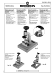
Figure 1: The BUILD-IT system is delivered with the parts shown here and listed in Table 1.
Figure 2: Detailed view of camera, lamp, beamers with remote control and adjustment screw (left). All
these parts have appropriate places for installation in the rack (right). Computer and keyboard are put
into the lower part of the rack.
Table 1: List of system parts.
System part:
1 computer
1 - 2 Beamers
1 Rack
1 Video camera
Software
1 Table
1 Mirror with suspension
2 Lamp holders
2 Bulbs
1 Portable screen
1 Brick
1 User manual
Name of product & technical details:
Compaq PWS 5100
Dual Processor board
1x 300 MHz Pentium II MMX processor
Minimum 64 MB RAM
Diamond Fire GL 3000 graphic card
PICPORT® STEREO Frame grabber from Leutron Vision GmbH
ASK A4 high resolution LCD projector, 800 x 600 pix, with serial
cable, remote control unit and positioning screw.
(Second projector is optional)
visualisation box, made by Tellware GmbH, (width x depth x height:
55 x 50 x 160 cm with suspended mirror
IR-sensitive camera, cable and objective
Single user software licence BUILD-IT
USM Schärer desk 2x2 meters, pearl-grey (optional)
Made by Tellware GmbH
Standard
Standard, 50 Watt
Projection screen PSTP007 2 x 2 meters, plus tripod (optional)
Passive interaction handler, made by Tellware GmbH
In English, colour print
3
SYSTEM DESCRIPTION
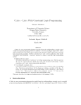
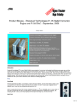
Figure 3: Planning takes place in the above view (left) and a dynamically bound perspective is offered
in the side view (right).
The design room of Figure 3 enables users, grouped around a table, to interact in a space of virtual
and real world objects. The vertical working area in the background (side view) gives a perspective
view of the plant. In the horizontal working area there are several views (above and height views,
menus) where objects can be selected and manipulated.
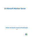
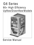
Selection
1
Fixing
3
2
Positioning and Rotation
Figure 4: The basic steps for user manipulations with the interaction handler (brick).
The basic principle of BUILD-IT is shown in Figure 4. Users select an object by putting the brick at the
object positions. The object can be positioned, rotated and fixed by simple brick manipulation. To
allow two handed operation, the system supports multi-brick interaction. A second effect of multi-brick
interaction, is that several users can take part in a simultaneous design process.
The application is designed to support providers of assembly lines and plants in the early design processes. However, it can easily be prepared to support a range of other applications, such as interior
architecture, city and urban planning. Graphical display is based on the class library MET++
(Ackermann, 1996). The system can read and render arbitrary virtual 3D objects. These objects are
sent from a CAD system to BUILD-IT using Virtual Reality Modelling Language (VRML). The system
has been engineered to send and receive numerous forms of meta-data.
4
SYSTEM ASSEMBLY
Figure 5: Put the computer and keyboard in the bottom of the rack. Arrange rack, table, chairs and
screen as shown here.
Figure 6: Position and cable one beamer at the top level of the rack. This is called the side view
beamer. Adjust the vertical screw of the side view beamer
Figure 7: Lead the mirror suspension and mirror into the rack.
5
Figure 8: Slide the second beamer into the rack from the front side of the rack (left) and cable it. This
is called the above view beamer. Fix and cable the video and lamps. Adjust the lateral positioner
(right) of the above view beamer. Turn on the system switch in the bottom of the rack.
Figure 9: Move the mirror suspension backwards or forewords (left) so that that the light field is
centred on the mirror (right).
Figure 10: It may be necessary to rotate the excentered, horizontal rod, situated up front in the rack.
6
Figure 11: Rotate mirror so that the image is only projected onto the table. Two wrong (left, centre)
positions one correct one (right) are show here.
BEAMER AND VIDEO ADJUSTMENT
The beamers should be correctly set, but they may need adjustment if they have been used for other
purposes. Direct remote control toward i) the projector or ii) the image, of the projector you want to
adjust. A single remote control can be used with both beamers.
Frequency adjustment:
Use text as benchmark image.
Remote control : Menu
Track ball
: 'Einstellung', 'Frequenz'
Lower white
: Press
Track ball
: All letters should be clearly visible and there should at most be one
band which is not accurate. This might be OK with the value 1692.
Left white
: Press for OK and one step up in menu hierarchy
Track ball
: ('Einstellung'), 'Feinabgleich'
Lower white
: Press
Track ball
: Do fine adjustment
Left white
: Press
Remote control : Press menu (OK)
Position adjustment:
For the ABOVE_VIEW beamer:
Remote control
: Menu
Track ball
: 'Einstellung', Position
Lower white
: Press
Track ball
: As far up as possible (approx. 467)
Adjusted left
(approx. 335)
Remote control
: Press menu (OK)
For the SIDE_VIEW beamer:
Remote control : Menu
Track ball
: 'Einstellung', Position
Lower white
: Press
Track ball
: As far down as possible (0)
Adjusted left
(approx. 323)
Remote control
: Press menu (OK)
The video camera should not need any adjustments.
7
CALIBRATION
Calibration is needed:
i) after system assembly, or
ii) when real and virtual objects do not correspond fully.
Double-click install.bat. You see the image processing window in your application. The camera
detects bricks as bright areas. You normally need to adjust the camera fixation to the rack and to
adjust it to give a sharp picture. If the camera still does not see full view you might need to adjust
buildit.Video.NumRow and buildit.Video.NumCol in the ETRC file (Appendix 2).
To stop this operation, click the X in the upper right window corner.
Figure 12: Place two bricks in image corners.
Now double-click calibrate.bat.
Figure 13: Calibration by putting brick at a reference section displayed in the corners of the above
view.
You can now work with the system. For all later system usage, it is sufficient to start up as described
in the proceeding chapter. To stop the application, click the X in the upper right window corner.
8
SYSTEM START-UP, USAGE AND SHUT DOWN
To start the system, double-click buildit.exe.
Figure 14: Selection of virtual object in virtual object store (menu). The menu has a left and right part,
as shown in this figure.
Figure 15: Selection, positioning and rotation of a machine in the virtual plant by moving the
interaction handler to the preferred position in the plant layout of the above view.
9
Figure 16: Fixing the machine by manually covering the surface of the interaction handler and then
removing it.
Figure 17: Removing an object by moving it back into one of the menus.
Figure 18: Scrolling in the above view in top-bottom sense (left) and left-right sense (right).
Figure 19: Scrolling in the height view.
10
Figure 20: Direct modification of object altitude in height view (left), and visual feedback in side view
(right).
Modification of the perspective in the height and side views is achieved by camera manipulation in the
above view. There is at least one camera available in the above view, but more can be activated from
the menu. Numerous cameras, each representing a distinct perspective, can exist at a time. The last
one selected determines the current perspective.
Camera
Scaling
Save and Print
Figure 21: Camera, scaling, save and print are permanently offered functions. They are described in
more detail in the following figures.
Figure 22: Camera allows for side view perspective modification.
11
Figure 23: Scaling applied on an object in the above view. First, select scaling function in the menu,
then go to the object to be scaled. Drawing away from the object, makes it bigger along the axis (x or
y) of movement, smaller when approaching the object.
Figure 24: Save and Print of the views. Printing only takes place if buildit.EnablePrinting(Bool) of the
ETRC file (Appendix 2) has been set.
Figure 25: Multi-brick interaction allows user to position two (or more) objects at a time.
12
Figure 26: Many persons can interact with multiple bricks at a time.
To stop the application, click the X in the upper right window corner.
13
INPUT OF 3D-CAD OBJECTS: VRML DATA
The BUILD-IT system understands 3D-CAD objects on the VRML format. VRML data describe the
complete geometry and visual characteristics of an object. Data exchange between a 3D-CAD system
and BUILD-IT is handled by the CAD-connection.
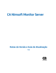
BUILD-IT
3D-CAD
geometric data
VRML
converter
.wrl
CAD-connection:
VRML data
VRML data +
coordinates list
Figure 27: Data flow from the 3D-CAD to the BUILD-IT system.
The connection between a 3D-CAD system and BUILD-IT is called CAD-connection and shown in
Figure 27. CAD users are presented with a list of all available objects and can select the geometric
data required for their specific planning session. The selected geometric data is converted to VRML
format and offered by the CAD system as ".wrl" files. Using the CAD-connection, the selected
geometric data is then sent as ".wrl" files to BUILD-IT.
A VRML based connection offers the important advantage of data compression, allowing for reduced
information flow and less object complexity. This feature is just as vital to object handling in the Web
as with the BUILD-IT system. Without data reduction, only high performance CAD systems would be
able to deliver multiple 3D object within acceptable time.
For the following CAD representations, conversion to VRML-DATA is supported:
1. CATIA native
(Version 3.x-4.1.7)
2. Unigraphics
(Version 11.1 - 13.0)
3. Auto CAD
(Version 13.0)
4. STEP PART 203
5. IGES 4.0
(depends on the CAD system)
6. MINICAD Macintosh
7. LOGOCAD
14
APPENDIX 1: DIRECTORIES AND FILES
Files in buildit main directory:
buildit.exe (The executable starting the BUILD-IT system)
ETRC (Resource file containing customer specific settings)
buildit.key (License information)
README (General information)
lvcamera.dat, lvlcxppx.dat,Lvreg.dat,leutron.ini, Cmnres32.dll,
Dsy_ms32.dll,lvlog32.dll,Lvrps32.dll,Prvph32.dll (Data needed for Image analysis)
View.dat (Keeps a list of the objects (directory and files) for the above view)
Menu_left.dat (Keeps a list of the objects (directory and files) for the left part of the menu)
Menu_right.dat (Keeps a list of the objects (directory and files) for the right part of the menu)
GestureServerData.dat (Protocol of current user interaction)
Directories in buildit main directory:
i) database
Files in database direcotry:
AffineMapping.dat (Data needed for calibration)
AffinePairs.dat (Data needed for calibration)
CalibrationPar.dat (Results of calibration)
camera.dat (Camera specific data)
ii) objects (User defined directory containing objects)
Files that can be located in arbitrary directories specified by customer
all object files (*.wrl) (Source directory specified in ETRC)
all converted object files (*.3d) (Location specified in Menu_left.dat, Menu_right.dat, or View.dat)
SnapInfo.dat (Location specified in ETRC)
15
APPENDIX 2: ETRC FILE; GENERAL CONFIGURATION
Table 2: ETRC file; parameter name, values, significance and files concerned.
Parameter name and parameter value
Significance
#buildit.SimulateRead(Bool): TRUE
Read brick positions from
file
buildit.SimulateWrite(Bool): TRUE
Write brick positions to file
buildit.ShowVideoInput(Bool): FALSE
Show video input in above
view (for camera adjustment
during system installation)
buildit.Calibrate(Bool):
FALSE
Do calibration
buildit.ObjectDirectory:
objects\\optics
Directory containing object
data, original .wrl files are
automatically converted to
*.3d files
buildit.ObjectScaling:
0.001
buildit.ObjectRotation:
90 90 0
Scaling factor from CAD
object data (*.wrl) to buildit
data (*.3d)
Rotation factor from CAD
object data (*.wrl) to buildit
data (*.3d)
Default position, where new
objects from CAD (*.wrl)
appear in the right menu
Display snapping box
Enable printing
Video image, number of
rows
Video image, number of
columns
Twin screens supported
Waiting time between each
check for new CAD data
Automatic updating of
View.dat, Menu_left.dat,
Menu_right.dat
File name of snap
information
Video x standard deviation
Video y standard deviation
Video angular standard
deviation
Display run time diagnosis
window
Run in debug modus
MET variable, do not
change
MET variable, do not
change
MET variable, do not
change
MET variable, do not
change
MET variable, do not
change
MET variable, do not
buildit.DefaultObjPosition:
200
buildit.ShowSnapPoints(Bool): FALSE
buildit.EnablePrinting(Bool): FALSE
buildit.Video.NumRow:
505
buildit.Video.NumCol:
600
buildit.TwinScreenGraphics(Bool): TRUE
buildit.MenuUpdateWaitTime 10000
buildit.AutoFileUpdate(Bool): FALSE
buildit.SnapInfoFile:
objects\\SnapInfo.dat
video.StdDevX:
video.StdDevY:
video.StdDevAngle:
.12
.1
0.3
*.TPR.LOG(Bool):
*.System.Debug(Bool):
*.System.MemStat:
FALSE
FALSE
1
*.System.MemStat.size(Num): -1
*.System.MemStat.cnt(Num): -1
*.System.IgnoreLevel(Num): 1000
*.System.AbortLevel(Num): 2000
*.ConvertThread.UseConvertThread(bool): FALSE
Files concerned
GestureServerData.dat
GestureServerData.dat
AffineMapping.dat
AffinePairs.dat
CalibrationPar.dat
*.wrl
*.3d
Menu_left.dat
Menu_right.dat
View.dat
View.dat
Menu_left.dat
Menu_right.dat
objects\\SnapInfo.dat
16
*.WindowSystem.DoubleBuffer(Bool):
ON
*.WindowSystem.MaxDepth(Num):
32
*.WindowSystem.GreyScale(Bool):
OFF
*.WindowSystem.HighlightColor(RGBColor):
2 0 255 0 0 0
*.WindowSystem.WindowHighlightColor(RGBColor):
2 0 168 168 168 0
*.WindowSystem.WindowBackgroundColor(RGBCol
or): 2 0 140 140 140 0
*.WindowSystem.DisableColor(RGBColor):
20
200 200 200 0
*.WindowSystem.Motif(Bool): 1
*.WindowSystem.Gamma:
1600
*.WindowSystem.UpdateTimeout(Num):
*.ScrollBar.Width:
*.Look.Border:
40
16
3
*.IAC.Debug(Bool):
TRUE
*.Font.Size(Num):
12
*.Font.Sys(Font):
Helvetica
*.Font.Appl(Font):
Helvetica
*.Font.Fixed(Font):
Courier
*.TextView.CaretColor(RGBColor): 2 0 255 0 0 0
*.TextView.DragAndDrop(Bool): YES
*.TextView.BatchTimeout(Num): 50
*.RTF.PromptForReadingVObjects(Bool): NO
*.ShellText.UseStyles(Bool):
*.CodeText.UseStyles(Bool):
YES
YES
*.CodeText.AllowGraphics(Bool): YES
*.CodeText.DeclarationSizeIncrement(Num):
2
*.CodeText.CommentColor(RGBColor): 2 0 0 0
255
*.CodeText.ClassColor(RGBColor): 6 0 0 0 0 255
*.CodeText.FunctionColor(RGBColor):
0
*.CodeText.TabPos(Num):
8
2 0 0 200
change
MET variable, do not
change
MET variable, do not
change
MET variable, do not
change
MET variable, do not
change
MET variable, do not
change
MET variable, do not
change
MET variable, do not
change
MET variable, do not
change
MET variable, do not
change
MET variable, do not
change
MET variable, do not
change
MET variable, do not
change
MET variable, do not
change
MET variable, do not
change
MET variable, do not
change
MET variable, do not
change
MET variable, do not
change
MET variable, do not
change
MET variable, do not
change
MET variable, do not
change
MET variable, do not
change
MET variable, do not
change
MET variable, do not
change
MET variable, do not
change
MET variable, do not
change
MET variable, do not
change
MET variable, do not
change
MET variable, do not
change
MET variable, do not
change
17
*.CodeText.AutoIndent(Bool):
YES
*.CodeText.WordWrap(Bool):
FALSE
*.CodeText.AutoReformatInterval:
*.CodeText.PicturePath:
4000
.:%e/doc:images
*.Slider.ThumbInk(Ink):
*.Slider.Ink(Ink):
*.ProgEnv.UseMapFiles(Bool):
YES
MET variable, do not
change
MET variable, do not
change
MET variable, do not
change
MET variable, do not
change
MET variable, do not
change
MET variable, do not
change
MET variable, do not
change
MET variable, do not
change
*.ProgEnv.SrcPath:
.:%e/src:%e/src/PROGENV:%e/src/PRINTERS:%e/
src/SUNWINDOW:%e/src/XWINDOW:%e/src/UNIX:
%e/src/STREAMS:%e/src/CONTAINER:%e/src/CO
NVERTERS:%e/src/LOOKS
*.Application.DebugButtonInAlert(Bool): YES
MET variable, do not
change
*.Document.MakeBackup(Bool): YES
MET variable, do not
change
*.Document.Size(Point):
1600 595
Size of BUILD-IT window
(both working areas)
*.Document.UndoLevel(Num):
10
MET variable, do not
change
*.Browser.FastIcons(Bool):
FALSE
MET variable, do not
change
*.Browser.Panes(Num):
3
MET variable, do not
change
*.AudioSystem.SamplingRate: 44100
MET variable, do not
change
write.followShowsNew:
YES
MET variable, do not
change
MIDISystem.Install(Bool):
NO
MET variable, do not
change
*3D.UseCaching
TRUE
MET variable, do not
change
18
APPENDIX 3: SNAPINFO.DAT FILE; SNAPPING AMONG OBJECTS
Table 3: SnapInfo.dat file; parameter name, values and significance.
Parameter name and parameter values
Significance
display:
Display the following information by program start-up
y
FileName:
Name of a machine/object
objects\mikron\karussell.3d
nPoint:
12
Only two of them are shown.
SnappingPoints
Each snap point, with snap position (x, y, z) in object
(x,y,z,_AZ,_AX,_AY,_sx,_sy,_sz)
co-ordinate system, snapping orientation in degrees in
[m,m,m,deg,deg,deg,m,m,m]:
object co-ordinate system (0..360) (_AZ ...), size of
snapping box in meters (size_x, size_y, size_z),
where box is centred around snap position (x, y, z)
0.76 0.44 0.50 30 0 0 0.4 0.4 0.3
0.44 0.76 0.50 60 0 0 0.4 0.4 0.3
...
FileName:
Same as above, another object
objects\mikron\buildit_triax.3d
nPoint:
1
SnappingPoints
(x,y,z,_AZ,_AX,_AY,_sx,_sy,_sz)
[m,m,m,deg,deg,deg,m,m,m]:
-0.20 0.1 0.00 0 0 0 0.4 0.4 0.3
FileName:
Same as above, another object
objects\mikron\buildit_schere.3d
nPoint:
1
SnappingPoints
(x,y,z,_AZ,_AX,_AY,_sx,_sy,_sz)
[m,m,m,deg,deg,deg,m,m,m]:
0.20 0.10 -0.20 180 0 0 0.4 0.4 0.3
Snapping:
Information about snapping, based on the above files
StaticObject: objects\mikron\karussell.3d
(1 2 3 4 5 6 7 8 9 10 11 12)
MovingObject: objects\mikron\buildit_triax.3d (1)
Add
StaticObject: objects\mikron\karussell.3d
(13 14 15 16 17 18 19 20 21 22 23 24)
MovingObject: objects\mikron\buildit_schere.3d (1)
Add
19
APPENDIX 4: ADDRESSES
TellWare GmbH
Am Oeschbrig 23
CH-8053 Zurich
Switzerland
Managing directors:
Martin Bichsel
Phone : +41-79-234 2462
Fax
: +41-1-632 1181
Email : [email protected]
Also available at ETH Zurich, Switzerland:
Phone : +41-1-6322429
Email : [email protected]
20
REFERENCES
Ackermann, P. (1996) Developing Object-Oriented Multimedia Software Based on the MET++ Application Framework. Heidelberg: dpunkt Verlag für digitale Technologie.
21
INDEX
Conceptual terms
direct object manipulation
design tool
Natural interaction
Natural User Interface (NUI)
tangible objects
graspable objects
computer mediated design
virtual 3D objects
Virtual Reality Modelling Language (VRML)
Computer Aided Design (CAD)
system designers
Working with BUILD-IT
BUILD-IT system
working area
view
above view
height view
side view
object menu
method menu
virtual machine store
interaction handler
projected image
virtual object
virtual plant
plant layout
object altitude
camera
current perspective
predefined contact lines
rotation
fixing
re-selection
removing
modification of object size and height
automatic snapping
scrolling
modification of the perspective
saving of the working area contents
printing of the views
CAD terms
3D-CAD system
CAD data
geometry
complete geometry
object
data structure
connection
CAD – BUILD-IT Connection
standard VRML interface
list with all available objects
planning session
data compression
reduced information flow
22
object complexity
in the web
high performance CAD systems
polyhedron
tangential
parts of millimetres precision
feedback
volume and surface information
suffix ".wrl"
initialisation
23