1
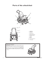
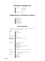
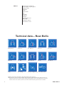
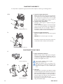
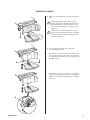
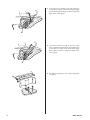
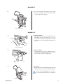
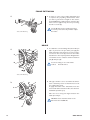
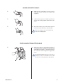
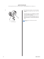
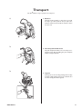
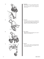
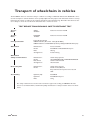
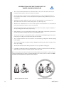
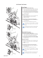
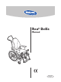
Rea® Bellis
Manual
English
Rea® Bellis
Rea® Bellis is a wheelchair with many adjustment options
and accessories. To ensure that you benefit as much as
possible from Rea® Bellis, and in order to do its options
justice, the chair must be tested and adjusted by competent personnel. We hope that you have also received
instructions for using your Rea Bellis in everyday life.
This manual includes a description of the parts of the
chair, simple adjustment options, how to use the Rea®
Bellis safely and how to transport it. The manual must be
read thoroughly before the chair is used.
Also included in this manual is a description of how all
accessories are fitted and slightly more advanced settings.
As the Rea® Bellis has many different components and
accessories, the appearance of the accessories you have
for your chair may differ from those shown.
NB!
!
Read the back cover of this user’s manual, which features
a number of points affecting your personal safety. Read it
carefully!
Invacare is only responsible for product changes carried
out by personnel who we authorise. We reserve the right
to make any changes to equipment and specifications without prior notice.
Delivery check
Check that all components match the delivery note. Any
transport damage must be reported immediately to the
transport company. Remember to keep the packaging until
the transport company has checked the goods and a settlement has been reached.
2
REA® BELLIS
Contents
Parts of the wheelchair
Standard equipment
Upholstery and frame colours
Accessories
Technical data – Rea Bellis
Assembly
Adjustments
Seat
Legrests/footrests
Footplates/calf pads
Central footplate
Backrest
Armrests
Seat unit
Manual chair with gas piston
Electrically operated chair
Rear wheels
Wheelchair heights
Frame extension
Brake
Carer-operated brake
Push handles/push bar
Anti-tip device
Transport
Transport of wheelchairs in vehicles
Observations
Restraint methods
Safety instructions/propelling techniques
Product description
Application
Guarantee
REA® BELLIS
4
5
5
5
6
7
9–20
9
10
10
11
13
13
14
14
15
16
17
18
18
19
19
20
21–24
23
24
25
26
28
28
29
3
Parts of the wheelchair
10
4
8
6
11
5
7
2
1
3
9
1.
2.
3.
4.
5.
6.
7.
8.
9.
10.
11.
Backrest
Push bar
Armrest
Rear wheel
Rear wheel plate
Anti-tip device
Brake
Castor
Seat
Legrest/Footrest
Foot plate
Lifting the wheelchair
Only lift by the frame of the chair (as shown in the
diagram).This applies at all times, irrespective of whether
when the user is or is not seated in the chair. Never lift
the chair by the removable armrests or by the footrests.
Ensure that the backrest and push bar are properly
secured.
4
REA® BELLIS
Standard equipment
Seat width:
39*– 41– 43* cm
44*– 46– 48* cm
49*– 51– 53* cm
Seat depth:
40–52 cm
* with flip-up armrests (Nice)
Upholstery and frame colours
Upholstery:
Green plush, "Strix"
Bordeaux plush
Grey dartex
Frame colours:
Dark blue RAL5013
Bordeaux CRED 2
Accessories
The Rea® Bellis has a wide range of accessories and options. Some of the accessories may not be available in certain countries.
REA® BELLIS
Backrest
Standard
Adjustable backrest
Seat
Standard
Seat cushions
Mistral
Seat and
backrest angle
adjustment
Carer-operated
Electrical operated by carer/user
Legrests
Legrests (angle-adjustable)
Amputee legrests
Footrests
Fixed footplate
Angle-adjustable and depth-adjustable
Foot plate extender
Heel strap
Castors
120–200 mm, pneumatic or solid, wide or narrow
Rear wheels
16", 20", 22", 24", pneumatic or puncture-proof
Vortex operating unit
Brakes
Carer-operated
User brake
One-arm brake
Foot brake
5
Others
Several types of hand rim
Several types of spoke guard
Reflectors Kit
Table Tray
Pump
Cane holder
Bag
Headrest
Neckrest
Push bar
Push handles brace
Pelvic Belt
Abduction cushion
Incontinence cover
Technical data – Rea® Bellis
41, 46, 51 cm
40 –52 cm
36 – 48,5 cm
52+7 cm
23–33 cm
29–51 cm
-1°–+15°
SW + 20,5 cm
110 cm
92–104 cm
32 kg
max 125 kg*
transport weight 20 kg
Tie down point**
* Maximum user weight is 100 kg if the chair is fitted with 100–120 mm castors.
**Our wheelchairs comply over and above ISO normal standards plus ISO 10542, which have additional features providing increased levels of occupant security and safety whilst travelling in a motor vehicle.Wheelchair users should
however transfer to the vehicle seat and use the vehicle installed restraint system whenever it is feasible.
6
REA® BELLIS
Assembly
1.
1. Backrest
The backrest is fitted by angling it upwards out of
the seat and then inserting it into the attachment
as shown in the diagram.
!
2.
Ensure that it “clicks” into the attachment
securely.
2. Armrests
Fit the armrests by pushing the two tubes into the
holes on the armrest holder. The armrest is then
pushed down into the attachment (A).
A
3a.
3. Legrests/footrests
The wheelchair can be equipped with either
legrests or footrests.
3a Legrests
Attach the legrests by pushing the tube at the upper
part of the legrests down into the tubes on the
wheelchair. You must angle the legrests outwards
when inserting them.
Lock the legrests by turning them inwards. The
legrests are automatically locked so there is no
risk of them coming off the wheelchair.
REA® BELLIS
7
3b.
3b Footrests
Attach the footrests by pushing the tube at the
upper part of the footrests down into the tubes
on the wheelchair. You must angle the footrests
outwards when inserting them.
Lock the footrests by turning them inwards. The
footrests are automatically locked so there is no
risk of them coming off the wheelchair.
4.
4. Rear wheel
The rear wheel is fitted by pressing button (B)
in the middle of the hub and keeping it pressed
in whilst inserting the axle into the rear wheel
attachment (C). It is important that the wheel is
fitted into place correctly and that the lock catch
(D) really has locked the wheel securely.
D
!
B
It is very important that you check that
the locking pin has actually locked the
wheel into position when the centre
button has been released. Take hold of the
wheels and try to detach them. This should
NOT be possible.
C
8
REA® BELLIS
Adjustments
SEAT
1.
1. Seat plate
The Rea Bellis has an anatomically designed seat
plate to provide proper stability and very good
seating comfort.
2.
2. Seat depth
Loosen the two screws at the legrest attachment
with a 5-mm Allen key and adjust the seat depth to
the desired position. Then retighten the screws.
Tools: 5 mm Allen Key
A
3.
Tools: 4 mm Allen Key
REA® BELLIS
3. Seat width
The width of the seat is adjusted by moving the side
supports. Pull the upholstery carefully to one side.
Loosen the two screws (A) with a 4-mm Allen key
and move the side supports to the desired position. There are three positions: position 1 creates
a narrower chair and position 3 creates a wider
chair.
9
FOOTRESTS/LEGRESTS
It is important to adjust the legrests, footrests and calf pads to obtain a good seating position.
1–2.
1. Legrests height adjustment
Adjust the height of the legrests by loosening the
screw (A) one turn with an Allen key. Pull the legrest until you have obtained the correct height
and the screw is caught by one of the recesses on
the legrest tube. Then retighten screw.
2. Legrests angle adjustment
The angle of the legrest is adjusted using the
handwheel (B).
Loosen the handwheel approx. one turn. The angle
can be set in intervals from 80° to 0°. Retighten the
handwheel when the correct angle is obtained.
The distance between the lowest part of the footrest and the surface must be at least 40 mm.
B
A
Tools: 5 mm Allen Key
3.
3. Footrests height adjustment
Adjust the height in the same way as the legrests
above.
NOTE! Don't touch the upper screw (C).
C
The distance between the lowest part of the footrest and the surface must be at least 40 mm.
A
Tools: 5 mm Allen Key
FOOTPLATES/CALF PADS
1.
1. Angle-adjustable footplates
Adjust the angle and the depth by loosening the
screw (A) at the footplate attachment with a 5
mm Allen key. Adjust the footplate to the correct
position and retighten the screw.
A
!
Tools: 5 mm Allen Key
2.
C
D
B
Tools: 5 mm Allen Key
10
!
Do not place anything on the footplate
when the screw is loose.
Other pin positions can be used if there is a
risk that the user could injure themselves, just
adjust the footplate to a more suitable position,
2. Calf pads
The calf pads can be fitted in four different depth
positions. Swing the pad forwards. Unscrew screw
(B) using an Allen key. Remove the large nut (C) on
the reverse side and place it in the other attachment hole. Move the calf pad to the new position
and secure it into place with the screw.
The height of the calf pads can easily be adjusted
using the handwheel (D).
REA® BELLIS
CENTRAL LEGREST
1. Adjust to the appropriate leg angle using knob
(A).
!
!
A
When adjusting the angle of the central
legrest, loosen the adjustment knob with one
hand and hold the foot plate with the other
hand to avoid trapping your or anyone else’s
fingers etc.
When the seat is tilted forwards on a chair
with a long legrest length and low seat height,
there is a risk of the legrest hitting the floor
and causing damage.
2. You can adjust the height of the legrest in
the following two ways:
Alternative 1: Loosen the Allen screw (B) on the
front of the telescopic tube, place the legrest in
the desired position and secure it into place using
the Allen screw.
B
Alternative 2: Loosen the Allen screw (C) by
the legrest attachment as shown in the diagram.
Adjust to the desired height and then retighten
the screw.
C
REA® BELLIS
11
3. Loosen the rear screw (D) on the side of the tube
and adjust the legrest to the desired angle. Retighten the screw. Repeat this procedure to adjust the
angle of the other legrest.
D
4. Loosen the frontal screw (E) on the side of the
tube to adjust the depth of the legrest.Tighten the
screw when you have found the desired depth.
Repeat this procedure to adjust the depth of the
other legrest.
E
5. The angle of the legrests can be adjusted upwards
if required.
12
REA® BELLIS
BACKREST
1.
1. You can easily adjust the backrest by loosening
the four screws with a 5-mm Allen key. Set at the
required height and re-tighten.
Tools: 5 mm Allen Key
ARMRESTS
1.
1. Armrest height
The height of the armrest can be adjusted by carefully pulling the armrest upholstery to one side
and then unscrewing screw (A) with a 5-mm Allen
key. Adjust to the desired height and retighten the
screw.
A
Tools: 5 mm Allen Key
2.
2. Armrest depth
The depth of the armrests is adjusted by loosening handwheel (B), adjusting the armrests to the
desired position and then retightening.
B
3.
3. Armrests
The armrests can be folded upwards. Push lever (C)
upwards and move the armrest straight upwards.
!
Take the risk of trapping fingers, etc. between
the armrests and backrest into consideration.
C
C
REA® BELLIS
13
Seat unit
The entire seat unit can be tilted backwards to provide a more relaxed position (resting), or forwards for a more
active position at mealtimes or when moving into or out of the chair, for example. The angle of the backrest unit
can be adjusted independently of the seat unit.
MANUAL CHAIR WITH GAS PISTON
1.
1. Tilt adjustment
The angle of the seat unit can be adjusted from –1º
to 15º. Move lever (A) on the right-hand side of the
chair upwards and tilt to the desired position.
A
2. Backrest angle adjustment
The angle of the backrest can be adjusted from 0º
to 30º. Move lever (B) on the left-hand side of the
chair upwards and angle to the desired position.
2.
B
3.
3. Mechanical backrest angle adjustment
If your wheelchair has mechanical backrest angle
adjustment, the backrest can only be adjusted in
fixed stages, 0º, 10º, 20º and 30º. Loosen screw (C)
at the backrest attachment and retighten the screw
in the desired position.
C
Tools: 6 mm Allen Key
13 mm fixed spanner
14
REA® BELLIS
ELECTRICALLY OPERATED CHAIR
1.
A
1. Tilt adjustment
The angle of the seat unit can be adjusted from –1º
to 15º. Tilt the seat unit by pressing hand control
(A). Clear symbols on the hand control show you
where to press.
!
2.
B
2. Backrest angle adjustment
The angle of the backrest can be adjusted from
0º to 30º. You adjust the angle of the backrest
by pressing hand control (B). Clear symbols
on the hand control show you where to press.
!
!
3.
The risk of trapping fingers, etc., is greater
in electric adjustments than in user-operated
adjustments. Bear in mind, for example, that
a child may get hold of the control box,
press the controls and get trapped, or trap
the user.
The risk of trapping fingers, etc., is greater in
electric adjustments than in user-operated
adjustments. Bear in mind, for example, that a
child may get hold of the control box, press the
controls and get trapped, or trap the user.
The electric engine to the backrest adjustment
mustn't be used when the backrest isn't locked
in it's attachment.
3. Charging the battery
If your wheelchair has electrically operated angle
adjustment, the battery must be charged from time
to time. If the angle adjustment function has been
used during the day it is convenient to use the
battery charger during the night.
The battery is charged by plugging the battery
charger, supplied with the chair, into a wall socket
and then connecting the charging cable into the
socket on the side of the control unit.
It takes approximately 12 hours to fully recharge
a 50 % discharged battery.
Work on the handset should only be carried out
by personnel who have been instructed in how it
works.
REA® BELLIS
15
REAR WHEELS
1.
1. Rear wheels
You can change the seating height by moving the
rear wheel attachment to the desired height. If
you change the height of the rear wheel, the castors must also be adjusted. The frame side must
be horizontal. Loosen the axle housing (A) using
an adjustable spanner. Check that you tighten the
axle housing properly when you have selected the
desired position.
A
The diagram illustrates the different positions for
the rear wheel. These depend on the size of the
wheel.
Tools: 24 mm fixed spanner
2.
2. Castors
The castors are moved by loosening nut (B),
moving screw (C) to the desired position and
retightening the screw.
B
C
You can obtain the correct seating height using this
table.
The propelling characteristics of the wheelchair
can be adjusted by moving the rear wheel attachment (A) in the depth.The same method is used
when changing castor size.
Tools: 13 mm fixed spanner
16
REA® BELLIS
WHEELCHAIR HEIGHTS
If you move the rear wheel forwards, your wheelchair becomes easier to propel, but also easier to tip.
Seatheights
REA Bellis
1
5296210
44,5
16"
2
1
120
44,5
16"
2
200
2
150/140
44,5
16"
2
3
180
44,5
16"
2
4
200
47
16"
1
1
180
47
16"
1
2
200
36
20"
4
3
38,5
20"
3
1
120
38,5
20"
3
3
150/140
120
41
20"
2
1
150/140
3
120
41
20"
2
2
180
4
150/140
1
1
200
43,5
20"
1
120
43,5
20"
1
2
150/140
43,5
20"
1
3
180
43,5
20"
1
4
200
41
22"
3
1
150/140
3
120
41
22"
3
2
180
4
150/140
2
1
200
43,5
22"
1
120
43,5
22"
2
2
150/140
43,5
22"
2
3
180
43,5
22"
2
4
200
46
22"
1
1
180
46
22"
1
2
200
45
24"
2
1
150
46
24"
2
2
180
46
24"
2
3
200
48,5
24"
1
1
200
02-02-25
REA® BELLIS
17
FRAME EXTENSION
1.
B
A
1. In order to create a more stable wheelchair and
to improve the propelling characteristics when
you have a great deal of weight on the castors,
the Rea® Bellis has a built-in frame extension.The
frame can be lengthened by 10 cm by loosening
the three screws (A).
!
Tools: 5 mm Allen key
Screw (B) must not be totally unscrewed.
Loosen by a few turns only and then adjust
the brake.
BRAKE
1. To obtain the correct braking effect, the brake pin
(B) is to press into the tyre when you apply the
brake. The brake may therefore need to be adjusted. Loosen the screw (A) and move the brake
attachment to the required position. Retighten the
screw.There is to be a distance of 15 mm between
pin (B) and tyre (C).
1.
C
B
!
Incorrect setting or use of the brake
reduces the brake effect.
A
Tools: 5 mm Allen key
2. This type of brake is to be used when the wheelchair is stationary and is not intended to be usde
for reducing the speed.
To apply the brake of the wheelchair, move the
lever forwards.To release the brake, move the lever
backwards (towards you).
2.
C
Take care not to trap your fingers between the
brake pin and tyre.
B
!
NB! Brake lever extenders must not be
fitted onto the Rea® Bellis.
A
18
REA® BELLIS
CARER-OPERATED BRAKE
1.
1. Brake when the wheelchair is moving: squeeze
both brake handles upwards and the brake will
be applied.
2.
2. Lock the brakes: squeeze the handle upwards and
move the lock catch (A) upwards.Then release the
handle.
A
3. Release the brakes: squeeze the handle upwards
and the lock catch will release automatically.
3.
!
Incorrect setting or use of the brakes will
reduce the braking effect.
PUSH HANDLES BRACE/PUSH BAR
1.
1. Adjust the height of the push handles/push bar by
loosening the levers (A) and then moving the push
handles/push bar upwards or downwards until you
have reached the desired height.Then retighten the
levers.
!
The pushbar/pushhandles brace must not be
pulled up so that it protrudes more than
19 cm over the top edge of the attachment.
A
REA® BELLIS
19
ANTI-TIP DEVICE
The anti-tip devices also act as step tubes. They are height-adjustable and can easily be set.
1.
1. Lift washer (A) and adjust to the desired height.
Check that the anti-tip device locks in the new
position.
A
B
Tools: 4 mm Allen key
10 mm fixed spanner
20
The anti-tip devices can be adjusted in the depth.
Loosen screw (B), move the anti-tip devices to the
desired position and retighten.
The chair is not at risk of tipping when the antitip devices are placed at the rear part of the rear
wheel and only 2 cm – 3 cm above the surface (the
floor).
!
Never forget to fold down the anti-tip
devices.
REA® BELLIS
Transport
The Rea® Bellis is easy to prepare for transport.
1.
1. Backrest
Hold the backrest firmly so that it does not fall
and injure you. Then pull out the pin (A) at the
backrest attachment and fold the backrest down
into the seat.
A
2.
2. Push bar/push handles brace
The push bar/push handles are loosened by loosening the levers (B) and pulling the push bar/push
handles straight upwards.
B
3.
3. Legrests
The legrests are loosened by pushing the lever (C)
forwards whilst turning the legrests outwards. You
can then simply lift off the legrests.
C
REA® BELLIS
21
4.
4. Footrests
The footrests are loosened by pushing the handle
(C) forwards or sidewards whilst turning the
footrests outwards. You can then simply lift off
the footrests.
C
5.
5. Armrests
In order to loosen the armrests, you must first fold
them upwards by pushing lever (A) upwards and
moving the armrests straight upwards. It is then
simple to remove them from the wheelchair.
A
6.
6. Rear wheels
Remove the rear wheels by pushing button (B) and
pulling the wheel straight out.
B
7.
22
C
7. Castors
Castors (+ castor fork) are removed by pressing
button (C) whilst pulling the wheel (with the castor
fork) straight downwards.
REA® BELLIS
Transport of wheelchairs in vehicles
The Rea® Bellis has been tested for safety in collisions according to ISO 7176-19:1999. The Rea® Bellis can be
used for transport in vehicles that have been specially adapted for this purpose. The wheelchair must be securely
fastened in the vehicle according to the methods described on the following page. Remember that the best solution is always to move the user from the wheelchair into a normal car seat.
TEST REPORT FROM DYNAMIC SAFETY RESTRAINT TEST
Test no:
Date:
09KM
07/03/00
Customer: Invacare Rea AB
Test no:
Date:
P300998A
19/02/03
Customer: Invacare Rea AB
Pulse specification
Test To Be Conducted
ISO/DIS 7176/19 (December 1999) (Rea® Bellis)
ISO/DiS 7176-19 and ISO 10542 (February 2003) (Rea® Bellis Transport)
Wheelchair
Manufacturer:
Model:
Mass:
Configuration:
Invacare Rea AB
Rea® Bellis and Rea® Bellis Transport
38,6 kg
Forward facing
Manufacturer:
Model:
Attachment:
Configuration
Unwin Safety Systems
4 Pt. WWR/ATF/K/R and WWR/HD/ATF/K/R
Unwin LowProfile Rail
4 Pt. Restraint
User safety belt
Manufacturer:
Model:
Unwin Safety Systems
Double Inertia, ATF, 3 Pt
Assy with short third point for Inertia and
Stalk
Test dummy
Hybrid II (LC)
Hybrid III
Mass:
Rea® Bellis
Rea® Bellis Transport
76 kg
Wheelchair
Safety restraint device
The safety restraint devices used in this test must be approved according to ISO10542. We have
chosen to work with Unwin, a well-known quality manufacturer of safety restraint devices for wheelchairs.
REA® BELLIS
23
OBSERVATIONS BEFORE TRANSPORT OF
WHEELCHAIRS IN VEHICLES
!
•
We recommend that wheelchair users should transfer to the seat of the vehicle and use the
installed restraint system of the vehicle whenever feasible.
•
The wheelchairs are tested in a basic configuration. The use in other configurations has not
been tested. See the manual, section "Test report from dynamic safety restraint test", for test
configuration.
•
Auxiliary wheelchair equipment is either secured to the wheelchair or removed from the
wheelchair and secured in the vehicle during transit. (i.e. table trays,,etc.).
•
Alterations or substitutions are not to be made to points of the wheelchair or to structural and
frame parts without the written consent of Invacare®.
•
A wheelchair-anchored pelvic belt must be fitted across the wheelchair occupant in addition to
the lap and diagonal and restraint (3-point belt).
•
Belt restraints are not to be held away from the body by wheelchair components or parts such
as armrests, postural restraints, wheels, etc. (See illustration below.)
•
The wheelchair must be securely fastened in the vehicle with an ISO 10542-2 approved 4-point
belt system, according to the methods described in the manual.
•
The occupied wheelchair must be tied down in an forward-facing configuration, with the parking
brake applied.
•
The test dummy weight is 75 kg, according to ISO 7176-19, although the chairs are approved for
users up to 125 kg.
•
The wheelchair backrest should be positioned as close as possible to 90 degrees.
•
If possible, a headrest should be used during transit, in order to reduce the risk of neck unjury.
Ensure that the headrest is mounted under the back of the head.
Please observe that even if these products and recommendations are provided in order to increase
security and safety, injury to vehicle occupants still might occur in the event of a collision or other
accidents and no guarantee is given in this respect.
Correct placement of belt
24
Incorrect placement of belt
REA® BELLIS
RESTRAINT METHODS
Rea® Bellis
B
C
A. Frontal restraints with straps
1. Connect the frontal straps around the main frame
of the wheelchair. If the straps have snap hooks,
connect them to the transport attachements.
2. Release brakes and tension front straps by pulling
the wheelchair backwards from the rear. Re-apply
wheelchair brakes.
B. Rear restraints
1. Attach the snap hooks on the rear straps to the
transport attachments on the rear frame.
3. Tighten the straps.
C. Fastening of pelvic belt and safety belt
1. Check that the pelvic belt on the wheelchair is
correctly fastened.
2. Fasten the 3-point safety belt over the user.
!
If pelvic belt on the wheelchair is missing
the user must be placed in the seat of the
vehicle.
!
The safety belt should not be kept from the
user’s body by the parts of the wheelchair.
A
B
Rea® Bellis Transport
C
A. Frontal restraints with straps
1. Connect the frontal straps around the main frame
of the wheelchair. If the straps have snap hooks,
connect them to the transport attachements.
2. Release brakes and tension front straps by pulling
the wheelchair backwards from the rear. Re-apply
wheelchair brakes.
B. Rear restraints
1. Attach the snap hooks on the rear straps to the
transport attachments on the rear wheel attachment.
3. Tighten the straps.
C. Fastening of pelvic belt and safety belt
1. Check that the pelvic belt on the wheelchair is
correctly fastened.
2. Fasten the 3-point safety belt over the user.
!
If pelvic belt on the wheelchair is missing
the user must be placed in the seat of the
vehicle.
!
The safety belt should not be kept from the
user’s body by the parts of the wheelchair.
A
REA® BELLIS
25
Safety instructions/propelling techniques
We recommend that you have the chair tested by the qualified person who has prescribed the wheelchair,
after he or she has made the adjustments that you request, taking your build and needs into account.We hope
that you have also received help in learning how best to use the wheelchair. Start by practising carefully until
you are familiar with the wheelchair’s possibilities and limitations.
Move to/from the wheelchair
Propel the wheelchair as near as possible to the seat that you want to
move to. Apply the brake. Remove the armrests or move them upwards
out of the way, and detach the legrests or swing them outwards. Do
not support yourself on the footplates as this may cause the chair to
tip forwards.
Stretching and leaning
Propel the wheelchair as near as possible.When stretching and bending,
do always have full contact between the backrest and the back otherwise
the wheelchair may tip over. Stretching behind the back is not recommended.
Propelling up a slope
Many experienced users can propel themselves up a slope. In order not
to lose control of the steering and to avoid tipping backwards, you should
always lean forwards whilst propelling up a slope. Propel the wheelchair
forwards using short, quick strokes applied to the hand rims, in order
to maintain speed and steering control.
Generally, help is needed on steep slopes.
If you have to stop on a slope, it is particularly important to ensure that
you do not make any sudden or unexpected forward movements when
you start moving the wheelchair forwards again. As the wheelchair is
already leaning backwards, such a movement may cause the wheelchair
to tip backwards.The maximum gradient of slopes that can be attempted
is varied between 3° and 13,5° depending on the user weight and the
adjustments of the wheelchairs.
Propelling down a slope
We recommend that you obtain the help of one or more assistants
when going down steep and wet slopes.
First check the slope to see if there are any particular hazards, potholes, slippery sections, etc. Never use the user-operated brake to slow
down.When you apply the brake on a downward slope, the wheels lock
and the wheelchair can suddenly pull to one side, tip sideways or stop
immediately, which may cause you to be thrown out of the chair.Always
control the speed with the hand rims. Remember that the hand rims
may become hot due to friction, and this may cause injury to your hands.
Try to propel down the slope in a straight line as much as possible.
26
REA® BELLIS
Onto a kerb
This method is for when the assistant is always behind the wheelchair and
it creates the greatest safety for the user.
The following advice is for the assistant:
Illustration 1) Adjust the anti-tip devices upwards. Ensure that the user’s feet
rest securely on the footrests and cannot slide off.Then tilt the wheelchair
backwards and push it forwards against the kerb.
Illustration 2) Lower the frontal part of the wheelchair onto the pavement
and place yourself as close to the chair as possible, before you lift up the
whole wheelchair.
Illustration 3) Lean forward and lift/roll the wheelchair over the pavement
edge.
Illustration 4) Lower the wheelchair onto the pavement so that the weight
is divided on all four wheels. Ensure that the wheelchair does not roll
backwards.
Off a kerb
Follow the procedure above, but in reverse order (step 4, 3, 2 and then 1)
to move off a kerb.
Kerbs – alternative method
This method is generally used by experienced assistants who are stronger
than average. It can also be used when the kerb or step is low and only
constitutes a minimal obstacle.
The assistant steps backwards onto the pavement and pulls the wheelchair
up onto the pavement. It is important for the assistant to use his or her
body correctly to prevent injury.Tip the wheelchair backwards and roll the
chair over the kerb onto the pavement. Take particular care if the kerb is
wet or slippery.
Escalators
Do not use escalators when you are in the wheelchair. Find out whether
there is a lift nearby.
Stairs
We advise you to avoid using stairs when you are in your wheelchair, where
possible. Choose an alternative route instead.
We recommend that you receive help from two assistants to get up and
down stairs. One assistant walks in front of the chair holding the frame of the
wheelchair, whilst the other assistant walks behind the chair, holding the push
handles. Check that the push handles/push bar are securely fixed in place
before you start. Fold the anti-tip devices upwards. Balance the wheelchair
on the rear wheels until the balance point is found. The wheelchair is then
rolled down the stairs, step by step, by letting the rear wheels roll over
the edge of each step. Assistants must not lift by gripping the removable
armrests or legrests. They must remember to lift the chair at the correct
points, to use their legs and to keep their backs as straight as possible.
REA® BELLIS
27
Product description
REA® BELLIS
The Rea® Bellis is a comfort wheelchair with seat and backrest angle adjustment functions. The lower part of the frame, the seat frame, the backrest
attachment and the push bar/push handles are made of high quality steel.
Chassis sections, seating sections, footrest attachments, armrest attachments
and back tubing are made of aluminium.
Footplates and side supports are made of reinforced plastic.The seat plate and
backrest plate are made of vacuum formed ABS-plastic. All metal and plastic
parts can be recycled.
Upholstery fabric is available in dartex and plush. These fabrics are washable.
The 6-cm thick seat pads and backrest pads are made of polyether.
The Rea® Bellis is available in three seat widths. Each seat width can be adjusted making it two centimetres narrower or two centimetres wider. The quick
release (QR) rear wheels are available in 20", 22" and 24" versions. You can
also choose 16" transportation wheels. The rear wheels can be placed in 16
positions in the rear wheel plate. The tyres are pneumatic or semi-solid. The
castors are available in the sizes 120 mm – 200 mm. The castor fork is quick
release and is height adjustable. The frame is length-adjustable.
The footrests are removable and the footplates are angle and depth-adjustable. It is also possible to fit footplate extenders to the footrests.
The armrests can be folded upwards and easily removed from the
wheelchair. The armrest pads are soft and upholstered in dartex.
The backrest is collapsible and the wheelchair can easily be transported in the
boot of a medium-sized car.
Only accessories approved and supplied by Invacare® are to be fitted onto
this product. The Rea® Bellis must be serviced regularly by an authorised
wheelchair technician or by Invacare’s® service personnel.
Application
The Rea® Bellis is a comfort wheelchair for people who require good seating
comfort and a great deal of support. The angle of the seat and that of the
backrest can be adjusted, thereby reducing the pressure on the user’s body.
The Rea® Bellis is very easy to propel. Propelling characteristics can easily be
adjusted in the rear wheel plate. The shaped push bar also makes the Rea®
Bellis easy to propel for an assistant, if applicable.
28
•
The Rea® Bellis can be used indoors and outdoors on dry, relatively
smooth surfaces. It should not be used in heavy rain, on snow-covered
and slippery surfaces, wet grass or on slopes.
•
The service life of the Rea® Bellis depends on the handling of the wheelchair and the degree of wear and tear it is subjected to.
•
Maximum user weight: 125 kg.
REA® BELLIS
Guarantee
We provide a 3-year guarantee from the delivery date. The guarantee is valid
from the day of delivery to the paying customer. Wear of parts is not included in the guarantee, for example upholstery, tyres, tubes, hand rims, castors
etc. Damages, caused by physical violence, carelessness or abnormal usage are
excluded. Damages, caused by heavier users than stated on the model plate,
are excluded.
Maintenance
It is easy to keep your Rea® Bellis wheelchair clean and in good condition.
Cleaning
• Wipe metal sections and the upholstery regularly with a damp cloth. A mild
detergent may be used. If necessary, the upholstery can be washed at 40ºC.
Ordinary washing powder/liquid can be used.
Touch-up paint
• If your wheelchair becomes scratched and the paintwork needs to be
improved, touch-up paint is available for most of our frame colours.
Wheels and tyres
• Wheel axles are to be wiped clean and lubricated with a drop of oil.
• Pneumatic tyres have valves similar to those on a car tyre, and the tyres
can
be pumped up using the same type of pump used for cars. The recom
mended air pressure is stated on the tyre. The recommended air pressure
for rear wheels is:
Standard tyres:
3.5 bar 50 psi
Low profile tyres
7.0 bar 90 psi
Recommended air pressure for castors is:
(200 mm)
8"
4,0 bar
(150 mm)
6"
2,5 bar
Technical servicing
• Only original parts or those approved and fulfilling Invacare’s specifications
may be used.
• All technical servicing is to be carried out by an authorised wheelchair
technician or by Invacare’s service department. The wheelchair should
be checked by authorised wheelchair technicians or Invacare's service
department once a year. The address and telephone number are on the
back cover of the manual.
• Check all parts of the wheelchair once a week. If you discover damage,
please contact Invacare immediately. The address and telephone number
are on the back cover of this manual.
Service life
We estimate that Rea® Bellis has a service life span of five years. It is difficult
to state the exact length of the service life of our products, and the length
stated is an estimated average life span based on normal use. The life span may
be considerably longer if the wheelchair is used to a limited extent, and if it is
used with care, maintained and handled properly. The life span may be shorter
if the wheelchair is subjected to extreme use.
Accidents/Near-accidents
Please inform your Invacare sales company (phone number is on the back
cover) of any accidents/near-accidents that were caused by this wheelchair
and that have led to/could have led to personal injury. The relevant authority
in your country must also be notified.
Testing
REA® BELLIS
Rea® Bellis has been tested and approved by The Swedish Handicap Institute
and is CE -marked according to the Medical Device Directive.
29
!
This symbol means warning
•
•
•
•
•
Check the following points before the wheelchair
is used:
– all parts are securely fastened to the frame.
– all handles and knobs are properly tightened.
Never lift the chair by the removable armrests,
or by the footrests. Ensure that the backrest and
push bar are securely fastened to the chair.
Remember that with every alteration to the
chair’s balance the inclination to tip, forwards or
backwards, also changes.
When fitting accessories etc. always take care not
to trap your fingers.
There is always an increased risk of trapping parts
of your body when tilting the wheelchair’s back
and seat.
•
•
•
•
•
•
The width of the seat should never be adjusted
so much so that the inside of the armrests press
against the side of the pelvis.
Always apply the brake before getting in or out of
the chair.
Never stand on the footplates when getting in
or out of the chair, because of the risk of tipping
over.
Check carefully that all knobs, screws and nuts are
properly tightened.
Note that the wheelchair is more likely to tip and
easier to tip backwards when the seat and backrest
are angled backwards.
Tightening the handles to the pushbar/pushhandles
brace heigt adjustment and the screws to the backrest attachment.
Manufacturer:
Invacare Rea AB
Växjövägen 303 S-343 71 DIÖ
SWEDEN
Sales companies:
Denmark:
Invacare n.v.
Autobaan 14
B-8210 Loppern, Brügge
Tel. +32 - 50 83 10 10
Fax. +32 - 50 83 10 11
Invacare A/S
Sdr. Ringvej 39
DK-2605 Brøndby
Tel. +45 - 36 90 00 00
Fax. +45 - 36 90 00 01
Holland:
Italy:
Invacare B.V.
Celsiusstraat 46 /
P.O. Box 123
NL-6716 BZ Ede
Tel. +31 - 318 695757
Fax. +31 - 318 695758
Spain:
Invacare S.A
C/Areny, s/n
Polígon Industrial de
Celerá
S- 17460 Celrá (Girona)
Tel. +34 - 972 493200
Fax. +34 - 972 493220
France
Invacare Poirier S.A.S
Les Roches
F.37230 Fondettes
Tel. +33 - 02 47 62 64 66
Fax. +33 - 02 47 62 64 10
Germany:
Austria, Switzerland and
Eastern Europe
Invacare GmbH
Dehmer Strasse 66
D-32549 Bad Oeynhausen
Tel. +49 - 57 31 754 0
Fax. +49 - 57 31 754 150
Norway:
Portugal:
Invacare Mecc San s.r.l.
Via dei Pini, 62
IT- 36016 Thiene VI
Tel. +39 - 445 380059
Fax. +39 - 445 380034
Invacare AS
Grensevingen 9
N-0603 OSLO 6
Tel. +47 - 22 57 95 00
Fax. +47 - 22 57 95 01
Invacare Lda
Rua Senhora de Campanhâ 105
PT-4369-001 Porto
Tel. +35 - 12 510 59 46
Fax. +35 - 12 510 57 39
Sweden and
Finland:
United Kingdom and
Ireland:
Invacare AB
Fagerstagatan 9 / Box 66
S-163 91 Spånga
Tel. +46 - 8 761 70 90
Fax. +46 - 8 761 81 08
Invacare (UK) Ltd.
South Road, Bridgend Industrial Estate
Bridgend
County Borough of Bridgend CF31 3PY
United Kingdom
Tel.: +44 1656 664 321
Fax.: +44 1656 667 532
Art.nr. 1428224 030613
Belgium: