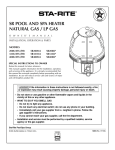
1
O
W
N
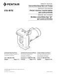
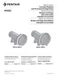
SPA PUMP
E
R’ S
M
A
N
U
A
L
794 0394
INSTALLATION, OPERATION & PARTS
115/230V/60Hz/1Ph TPEA & TPRA Series MODELS
1 HP
1-1/2 HP
1-1/2 HP
2 HP
2 HP
2-1/2 HP
TPEAE-165L
TPEAF-166L
TPEAG-167L
TPEAAG-168L
TPRAE3-165
TPRAF-174L
TPRAYF-174S
TPEAG-167LS TPEAYG-175L
TPEAYG-175LS
TPEAAYG-168L
This manual should be given to the owner of the pump.
Customer Support (800) 831.7133
S330 Rev B 5/15/14
PUMP WARNINGS AND SAFETY INSTRUCTIONS
For Pool and Spa Pumps (Non SVRS Pumps)
FAILURE TO FOLLOW ALL INSTRUCTIONS AND WARNINGS CAN RESULT IN SERIOUS BODILY
INJURY OR DEATH. THIS PUMP SHOULD BE INSTALLED AND SERVICED ONLY BY A QUALIFIED POOL
SERVICE PROFESSIONAL. INSTALLERS, POOL OPERATORS AND OWNERS MUST READ THESE
WARNINGS AND ALL INSTRUCTIONS IN THE OWNER'S MANUAL BEFORE USING THIS PUMP. THESE
WARNINGS AND THE OWNER'S MANUAL MUST BE LEFT WITH THE POOL OWNER.
Warnings and safety instructions for Pentair Aquatic Systems pumps and other related products are available
at: http://www.pentairpool.com/pool-owner/safety-warnings/ Call (800) 831-7133 for additional free copies
of these instructions. Please refer to www.pentairpool.com for more information related to Pentair Aquatic
systems pumps.
SUCTION ENTRAPMENT HAZARD: STAY OFF THE MAIN DRAIN AND AWAY FROM ALL SUCTION
OUTLETS!
F
THIS PUMP PRODUCES HIGH LEVELS OF SUCTION AND CREATES A STRONG VACUUM AT THE
MAIN DRAIN AT THE BOTTOM OF YOUR POOL AND SPA. THIS SUCTION IS SO STRONG THAT IT CAN
TRAP ADULTS OR CHILDREN UNDER WATER IF THEY COME IN CLOSE PROXIMITY TO A POOL OR
SPA DRAIN OR A LOOSE OR BROKEN DRAIN COVER OR GRATE.
THE USE OF UNAPPROVED COVERS OR ALLOWING USE OF THE POOL OR SPA WHEN COVERS ARE MISSING,
CRACKED OR BROKEN CAN RESULT IN BODY OR LIMB ENTRAPMENT, HAIR ENTANGLEMENT, BODY ENTRAPMENT, EVISCERATION AND/OR DEATH.
The suction at a pool or spa drain or outlet can cause:
Limb Entrapment: When a limb is sucked or inserted into an opening resulting in a mechanical bind or swelling. This
hazard is present when a drain cover is missing, broken, loose, cracked or not properly secured.
Hair Entanglement: When the hair tangles or knots in the drain cover, trapping the swimmer underwater. This hazard is
present when the flow rating of the cover is too small for the pump or pumps.
Body Entrapment: When a portion of the body is held against the drain cover trapping the swimmer underwater. This
hazard is present when the drain cover is missing, broken or the cover flow rating is not high enough for the pump or
pumps.
Evisceration/Disembowelment: When a person sits on an open pool (particularly a child wading pool) or spa outlet and
suction is applied directly to the intestines, causing severe intestinal damage. This hazard is present when the drain cover
is missing, loose, cracked, or not properly secured.
Mechanical Entrapment: When jewelry, swimsuit, hair decorations, finger, toe or knuckle is caught in an opening of an
outlet or drain cover. This hazard is present when the drain cover is missing, broken, loose, cracked, or not properly
secured.
NOTE: ALL SUCTION PLUMBING MUST BE INSTALLED IN ACCORDANCE WITH THE LATEST NATIONAL AND LOCAL
CODES FOR SWIMMING POOLS, SPAS AND HOT TUBS, INCLUDING NSPI STANDARDS AND CPSC GUIDELINES.
READ AND KEEP THESE INSTRUCTIONS FOR FUTURE REFERENCE
i
PUMP (Non SVRS) WARNINGS AND SAFETY INSTRUCTIONS
TO MINIMIZE THE RISK OF INJURY DUE TO SUCTION ENTRAPMENT HAZARD:
• Pools and spas should utilize a minimum of two drains per pump.
• A properly installed and secured ANSI/ASME A112.19.8 approved anti-entrapment suction
cover must be used for each drain.
• Each suction cover must be installed at least three (3') feet apart, as measured from the
nearest point to nearest point.
• Regularly inspect all covers for cracks, damage and advanced weathering.
• If a cover becomes loose, cracked, damaged, broken or is missing, close the pool or spa
immediately, shut off the pump, post a notice and keep the pool or spa closed until an
appropriate certified cover is properly installed.
• Replace drain covers as necessary. Drain covers deteriorate over time due to exposure to
sunlight, pool chemicals and weather.
• Avoid getting hair, limbs or body in close proximity to any suction cover, pool drain or outlet.
• Use a safety vacuum release system ("SVRS"), suction limiting system or automatic pump
shut-off system.
• Disable suction outlets or reconfigure into return inlets.
A clearly labeled emergency shut-off switch for the pool pump and spa jet pump must be in an easily
accessible, obvious place near the pool or spa. Make sure bathers know where it is and how to use it in case
of emergency.
The Virginia Graeme Baker (VGB) Pool and Spa Safety Act creates new requirements for owners and operators of commercial swimming
pools and spas.
Commercial pools or spas constructed on or after December 19, 2008, shall utilize:
(A) A multiple main drain system without isolation capability with suction outlet covers that meet ASME/ANSI A112.19.8a Suction Fittings
for Use in Swimming Pools, Wading Pools, Spas, and Hot Tubs and either:
(i) A safety vacuum release system (SVRS) meeting ASME/ANSI A112.19.17 Manufactured Safety Vacuum Release systems (SVRS)
for Residential and Commercial Swimming Pool, Spa, Hot Tub, and Wading Pool Suction Systems and/or ASTM F2387 Standard
Specification for Manufactured Safety Vacuum Release Systems (SVRS) for Swimming pools, Spas and Hot Tubs or
(ii) A properly designed and tested suction-limiting vent system or
(iii) An automatic pump shut-off system.
Commercial pools and spas constructed prior to December 19, 2008, with a single submerged suction outlet shall use a suction outlet cover that
meets ASME/ANSI A112.19.8a and either:
(A) A SVRS meeting ASME/ANSI A112.19.17 and/or ASTM F2387, or
(B) A properly designed and tested suction-limiting vent system, or
(C) An automatic pump shut-off system, or
(D) Disabled submerged outlets, or
(E) Suction outlets shall be reconfigured into return inlets.
HAZARDOUS PRESSURE: STAND CLEAR OF PUMP AND FILTER DURING START-UP
Pool and spa circulation systems operate under high pressure. When any part of the circulating system (i.e.
lock ring, pump, filter, valves, etc.) is serviced, air can enter the system and become pressurized.
Pressurized air can cause the pump housing cover filter lid and valves to violently separate which can result in
severe personal injury or death. Filter tank lid and strainer cover must be properly secured to prevent violent
separation. Stand clear of all circulation system equipment when turning on or starting up pump.
CAUTION!: Electrical controls such as on/off switches, timers, and control systems, etc. should be properly
installed to allow the operation (start-up, shut-down, or servicing) of any pump or filter without requiring the user
to place any portion of his/her body over or near the pump strainer lid or filter lid. Such installation should allow
the user to stand clear of the filter and pump during system start-up, shut down or servicing of the system.
Before servicing pool and spa equipment, make note of the filter pressure. Be sure that all controls are set to
ensure the system cannot inadvertently start during service. Turn off all power to the pump. IMPORTANT:
Place filter manual air relief valve in the open position and wait for all pressure in the system to be
relieved.
Before starting the system, fully open the manual air relief valve and place all system valves in the "open"
position to allow water to flow freely from the pool and spa back to the pool or spa. Stand clear of all pool and
spa equipment and start the pump. IMPORTANT: Do not close filter manual air relief valve until all
pressure has been discharged from the valve and a steady stream of water appears. Observe filter
pressure gauge and be sure it is not higher than the pre-service condition.
ii
READ AND
FOLLOW SAFETY
INSTRUCTIONS!
STA-RITE SPA PUMP
To avoid unneeded service calls, prevent possible
injuries, and get the most out of your pump, READ THIS
MANUAL CAREFULLY!
The Sta-Rite ‘TPEA’ Series pump:
This is the safety alert symbol. When you see this
symbol on your system or in this manual, look for
one of the following signal words and be alert to the
potential for personal injury.
• Is designed for use with spas.
• Is an excellent performer; durable, reliable.
warns about hazards that will cause death,
serious personal injury, or major property damage if
ignored.
Table of Contents
Safety Instructions ......................................................2
Installation ................................................................3-4
warns about hazards that can cause death,
serious personal injury, or major property damage if
ignored.
Electrical...................................................................4-6
Operation.....................................................................6
warns about hazards that will or can cause
minor personal injury or property damage if ignored.
NOTICE indicates special instructions not related to
hazards.
Carefully read and follow all safety instructions in this
manual and on equipment. Keep safety labels in good
condition; replace if missing or damaged.
Storage/Winterizing ..................................................6-7
Pump Service ...........................................................7-8
Troubleshooting Guide.................................................9
Repair Parts List ........................................................10
Incorrectly installed or tested equipment
may fail, causing
severe injury or property damage.
Read and follow instructions in owner's manual when
installing and operating equipment. Have a trained pool
professional perform all pressure tests.
IMPORTANT SAFETY
INSTRUCTIONS
Always follow basic safety precautions with this
equipment, including the following.
1. Do not connect system to a high pressure or city water
system.
2. Use equipment only in a pool or spa installation.
To reduce the risk of injury, do not
permit children to use this product unless they are
closely supervised at all times.
3. Trapped air in system can cause permanent equipement
danage. BE SURE all
air is out of system before operating or testing equipment.
This pump is for use with permanently
installed pools and may also be used with hot tubs
and spas if so marked. Do not use with storable
pools. A permanently installed pool is constructed in
or on the ground or in a building such that it cannot
be readily disassembled for storage. A storable pool
is constructed so that it may be readily disassembled
for storage and reassembled to its original integrity.
Before pressure testing, make the following safety checks:
• Check all clamps, bolts, lids, and system accessories before
testing.
• Release all air in system before testing.
• Tighten Sta-Rite trap lids to 30 ft. lbs. (4.1 kg-m) torque for
testing.
• Water pressure for test must be less than 25 PSI (7.5
kg/cm2).
o
• Water Temperature for test must be less than 100 F.
o
(38 C).
SAVE THESE
INSTRUCTIONS
• Limit test to 24 hours. After test, visually check system to be
sure it is ready for operation. Remove trap lid and retighten
hand tight only.
NOTICE: These parameters apply to Sta-Rite equipment only.
For non-Sta-Rite equipment, consult manufacturer.
2
NOTICE: When connecting threaded pipe directly to
pump, use thread seal tape to seal connections. Do not
use pipe dope; pipe dope causes cracking in some
plastics and may damage components in piping system.
When connecting threaded pipe to pump with union
half, use thread seal tape between pipe and union
adapter. Union collar to pump should be assembled dry
and hand-tight. Make sure O-ring is seated in groove.
NOTICE: Pump suction and discharge connections
have molded in thread stops. DO NOT try to screw pipe
in beyond these stops.
INSTALLATION
Only qualified, licensed personnel should install pump
and wiring.
Pump mount must:
Be solid - Level - Rigid - Vibration free. (To reduce
vibration and pipe stress, bolt pump to mount.)
Install pump with suction port below water level (flooded
suction) only. Pump does not lift water.
Allow use of short, direct suction pipe (To reduce friction
losses).
Allow for gate valves in suction and discharge piping.
Have adequate floor drainage to prevent flooding.
Be protected from excess moisture.
Taping Instructions:
Use only new or clean PVC pipe fittings.
Wrap male pipe threads with one to two layers of thread
seal tape. Cover entire threaded portion of pipe.
Do not overtighten or tighten past thread stop in pump
port!
If leaks occur, remove pipe, clean off old tape, rewrap
with one to two additional layers of tape and remake the
connection.
NOTICE: Support all piping connected with pump!
Discharge
Port
Suction
Port
Piping:
Drain
Plug
Pump may be bolted to level
foundation or mounting bracket.
Use at least 1-1/2" (38mm) pipe (use 2"(51mm) pipe if
possible). Increase size if a long run is needed. When
using 1-1/2" pipe, connect to pump with 1-1/2" to 2" (38
to 51mm) reducing adapter.
To avoid strains on the pump, support both suction and
discharge pipes independently. Place these supports
near the pump.
To avoid a strain left by a gap at the last connection,
start all piping at the pump and run pipe away from the
pump.
To avoid airlocking, slope suction pipe slightly upward
toward the pump.
NOTICE: To prevent flooding when removing pump for
service, all flooded suction systems must have gate
valves in suction and discharge pipes.
791 0394
Figure 1
Port threads:
Internal - 2" NPT for direct connection to pipe. External 3" Buttress. Fits Sta-Rite 38405 - 4094 Union Collar for
quick disconnect pipe connection.
Order: Union Kit #77703-0105 (1-1/2" and 2" Union
Halves).
Allow adequate access for servicing pump and piping.
3
ELECTRICAL
Fittings:
Fittings restrict flow; for best efficiency use fewest
possible fittings.
Avoid fittings which could cause an air trap in suction
piping.
Pool and spa drains must conform to International
Association of Plumbing and Mechanical Officials
(IAPMO) standards.
Use only non-entrapping suction fittings and dual
suction outlets.
Ground motor before
connecting to electrical
power supply. Failure to
ground motor can cause
severe or fatal electrical
shock hazard.
Do not ground to a gas
supply line.
Hazardous voltage.
Can shock, burn,
or cause death.
To avoid dangerous or
fatal electrical shock,
turn OFF power to motor
before working on electrical
connections.
Ground pump before
connecting to
power supply.
Ground Fault Circuit
Interrupter (GFCI)
tripping indicates an electrical
problem. If GFCI trips and will
not reset, have a qualified electrician inspect and repair
electrical system.
18-61/64 (481) Max
17-5/16 (440) Min
10-11/16 (271)
2-1/16 (52)
1/2-14 SPT
10-7/8
(276)
8-9/16
(218)
Steel Base Models
(LS Suffix)
5-13/16
(148)
12-1/4
(311)
2(51)
5-9/16
(143)
7-17/32 (191)
11-5/32 (283)
Plastic Base Models
(L Suffix)
Figure 2 – Outline Dimensions in Inches (mm)
4
1314 1094
6-1/2 (165)
2-3/4
(70)
Use Ground Fault Circuit Interrupter (GFCI) as master
on-off switch; it will sense a short circuit to ground and
disconnect power before it becomes dangerous to pool
users. Test according to maker’s instructions.
In case of power outage, check GFCI for tripping (which
will prevent normal water circulation). Reset if
necessary.
Exactly match supply voltage to motor nameplate
voltage. Incorrect voltage can cause fire or
seriously damage motor and voids warranty. If in doubt
consult a licensed electrician. See Figure 4.
Voltage
Voltage at motor must be not more than 10% above or
below motor nameplate rated voltage or motor may
overheat, causing overload tripping and reduced
component life. If voltage is less than 90% or more than
110% of rated voltage when motor is running at full
load, consult power company.
Risk of dangerous or fatal electrical shock.
Be sure that power to the motor circuit is off before
working on wiring, wiring connections, or motor. Reinstall the motor end cover and all other wiring covers
before turning on the power.
1. Turn off power.
2. Remove the motor end cover.
Grounding/Bonding
Install, ground, bond and wire motor according to local
or National Electrical Code requirements.
Permanently ground motor. Use green ground terminal
provided under motor canopy or access plate (See Fig.
3); use size and type wire required by code. Connect
motor ground terminal to electrical service ground.
To Wire a Single Speed, Single Voltage Motor
There are two terminals labeled L1 and L2. Attach the
power leads to these terminals. Either wire may attach to
either terminal.
To Wire a Dual-Voltage Motor
BONDING
LUG
Dual voltage motors have a plug to change from 230
volts (factory setting) to 115 volts.
1. If you have 230 volts motor supply voltage, confirm
that the plug is set for 230 volts. The arrow on the
plug will point to the 230 volt position. Note that plug
only connects with one prong in this position.
2. If you have 115 volt supply, pull the plug straight up
and place it on the two brass prongs as shown.
NOTE: Arrow is highlighted for clarity.
GREEN
GROUND
SCREW
510 0993
Figure 3 – Typical ground screw and bonding lug
locations.
Bond motor to pool structure. Use a solid copper
conductor, size No. 8 AWG (8.4 sq.mm) or larger. Run
wire from external bonding lug (see Fig. 3) to reinforcing
rod or mesh.
Connect a No. 8 AWG (8.4 sq.mm) solid copper
bonding wire to the pressure wire connector provided
on the motor housing and to all metal parts of the
swimming pool, spa, or hot tub and to all electrical
equipment, metal piping or conduit within 5 feet (1.5 m)
of the inside walls of swimming pool, spa, or hot tub.
Wiring
Figure 4A -Voltage Change
Plug Set for 230 Volts
Pump must be permanently connected to circuit (see
Figure 4A and 4B); be sure no other lights or appliances
are on the same circuit. Match wire sizes to Table I
(Pg. 6).
NOTICE: To prevent dirt, rain, bugs, etc., from entering
motor when not wiring with conduit, be sure to seal wire
opening on end of motor.
5
Figure 4B Voltage Change
Plug Set for 115 Volts
OPERATION
To Wire a Two-Speed Motor
Wire the pump as shown in the diagram.
NOTICE: NEVER run pump dry. Running pump dry may
damage seals, causing leakage and flooding. Fill pump
with water before starting motor.
Ground (Green)
Low Speed
L2=COM
L1=HI
A=LOW
L2
Do not block pump
suction. To do so with
body may cause severe or
fatal injury. Small children
using pool must ALWAYS
have close adult supervision.
230
Volt
Lines
A
Back of
motor
with
Terminal
Board
Common
Power Supply for
Optional Timer.
L1
High Speed
Remote
SPDT
Switch
If using timer, Connect
Timer Motor to Low Speed Only
Circuit
Protector
Priming Pump
4558 0304
Hazardous suction.
Can trap hair or body
parts, causing severe
injury or death.
Minimum switch and timer amp rating must equal Branch Fuse
Rating given in "Recommended Fusing and Wiring Data" table.
Figure 4C - 2-Speed Motor Wiring Diagram
Do not block suction.
Do not operate system
with broken or missing
drain covers.
Release all air from filter and
piping system: see filter
owner’s manual.
In a flooded suction system
(water source higher than
pump), pump will prime itself
when suction and discharge
valves are opened.
Storage/Winterizing:
NOTICE: Allowing pump to freeze will damage pump
and void warranty!
NOTICE: Do not use anti-freeze solutions (except
propylene glycol) in your pool/spa system. Propylene
glycol is non-toxic and will not damage plastic system
components; other anti-freezes are highly toxic and may
damage plastic components in the system.
TABLE I - RECOMMENDED FUSING AND WIRING DATA
NOTICE: Series TPEA and TPRA pumps use 60 Cycle current only.
Serv. to Motor - Dist. in Ft. (M)
Motor
HP
Branch Fuse
Rating Amps*
TPEA Models:
1
1-1/2
2
2-1/2
20/15
25/15
15
15
Max Load
Amps
12.6/6.3
16.0/8.0
10.4
11.2
TPEAY Models (2-speed):
2
15
2-1/2
15
10.1/3.7
11.9/3.5
TPRA Models:
1
1-1/2
2
3.6/1.8
19.2/9.6
12.0
15
25/15
15
Voltage/
Hz/Phase
0-100'
(0-30)
101-200'
(30-60)
201-300'
(60-90)
115/230/60/1 12(3)/14(2) 10(5/14(2) 8(7)/14(2)
115/230/60/1 12(3)/14(2) 8(7)/14(2) 6(13)/14(2)
230/60/1
14(2)
14(2)
14(2)
230/60/1
14(2)
12(3)
12(3)
230/60/1
230/60/1
14(2)
14(2)
14(2)
12(3)
14(2)
12(3)
208-230/460/60/3 14(2)
14(2)
14(2)
115/230/60/1 10(5)/14(2) 8(7)/14(2) 6(13)/12(3)
230/60/1
14(2)
14(2)
12(3)
TPRA Models (2-Speed):
1-1/2
15
9.2/2.5
230/60/1
14(2)
14(2)
12(3)
5TPRAY Model (2-speed):
1-1/2
15
8.3/3.0
230/50/1
14(2)
14(2)
12(3)
6
}
AWG
Wire
Size
(mm2)
PUMP SERVICE
Drain all water from pump and piping when expecting
freezing temperatures or when storing pump for a long
time (see instructions below).
Keep motor dry and covered during storage.
To avoid condensation/corrosion problems, do not
cover pump with plastic.
For outdoor/unprotected installations:
1. Enclose entire system in a weatherproof enclosure.
2. To avoid condensation/corrosion damage, allow
ventilation; do not wrap system in plastic.
3. Use a 40% propylene glycol/60% water solution to
protect pump to -50°F (-46°C).
Pump should only be serviced
by qualified personnel.
Be sure to prime pump
(Pg. 6) before starting.
1. STOP PUMP before
proceeding.
2. CLOSE GATE VALVES in
suction and discharge pipes.
Hazardous voltage.
Can shock, burn,
or cause death.
Draining Pump
1. Pump down water level
below all inlets to the pool.
Hazardous voltage.
Can shock, burn,
or cause death.
Disconnect power
before working
on pump or motor.
Disconnect power
before working
on pump or motor.
To avoid dangerous or
fatal electrical shock
hazard, turn OFF power to
motor before draining pump.
2. Cap inlet piping after
draining to keep water out
of the pipes.
3. To prevent pump from
freezing, drain the pump
body through the drain
fitting provided.
4. Be sure motor is kept dry
and covered.
3. RELEASE ALL PRESSURE
from pump and piping system.
To avoid dangerous or
fatal electrical shock
hazard, turn OFF power to
motor before working on
pump or motor.
If shaft seal is worn or damaged, repair as follows:
Pump Dissasembly/Removing Old Seal
Disconnect power to pump motor.
Be sure gate valves on suction and return piping
are closed before starting work.
Release all pressure by opening all vents before
starting work.
1. Drain pump through drain fitting on bottom of pump
body.
2. Remove 6 nuts, lockwashers and flat washers
holding seal plate to pump body. Pull seal plate and
motor away from pump body. (You may have to
CAREFULLY use a screwdriver to separate body
from seal plate.)
Startup For Winterized Equipment
1. Remove any temporary weather protection placed
around system for shutdown.
2. Follow filter manufacturer’s instructions for
reactivation of the filter.
3. Inspect all electrical wiring for damage or
deterioration over the shutdown period. Have a
qualified serviceman repair wiring as needed.
4. Inspect and tighten all watertight connections.
5. Open all valves in suction and return piping.
6. Remove any winterizing plugs in piping system.
3. Remove seven screws and washers holding diffuser
to seal plate. Remove diffuser.
4. Remove motor canopy. Being careful not to touch
capacitor terminals, loosen capacitor clamp and
move capacitor to one side.
5. Hold shaft with 7/16" open-end wrench on motor
shaft flats.
6. Unscrew impeller from shaft (turn counterclockwise
when facing it).
NOTICE: On 2 and 2-1/2 HP models, remove
impeller screw (left hand thread - turn clockwise)
and gasket before removing impeller. Inspect
gasket for damage, cracks, etc. Replace if
damaged.
7. Drain all antifreeze from system.
8. Close all drain valves and replace all drain plugs in
piping system.
9. Prime pump according to instructions on Page 6.
7
3. If seat still will not locate properly, place a
cardboard washer over the polished face and use a
piece of 3/4" (19mm) standard pipe for pressing
purposes.
NOTICE: Be sure not to scratch or mar polished
surface or seal will leak.
7. Remove four screws holding seal plate to motor.
8. Place seal plate face down on flat surface and tap
out ceramic seat (Fig. 5).
4. Replace slinger on end of motor shaft so that
impeller sleeve will push it into position. If slinger
shows signs of wear or damage, replace it.
5. Remount seal plate on motor. Tighten bolts to 60-80
inch-lbs. (69-92 kg/cm) torque.
6. Apply a small amount of liquid detergent to inside
diameter of rotating half of seal.
7. Slide rotating seal member, polished carbon face
out, over impeller sleeve until rubber drive ring hits
back of impeller.
NOTICE: Be sure not to nick or scratch polished
seal face; seal will leak if face is damaged.
Figure 5
9. Remove slinger from motor shaft and inspect for
damage or abrasion.
8. Screw impeller onto shaft (clockwise); this will
automatically locate seal in seal plate.
NOTICE: On 2 HP, 2-1/2 HP and 3-Phase models;
install impeller gasket and lock screw (left-hand
thread - turn counterclockwise). Torque lock screw
to 50-55 inch-lbs. (57.6-63 kg/cm).
10. Clean seal cavity in seal plate and clean motor
shaft.
Pump Reassembly/Installing New Seal
9. Mount diffuser on seal plate; tighten screws to 1014 inch-lbs. (11.2-16.1 kg/cm) torque.
1. Ceramic seat must be clean and free of dirt, grease,
dust, etc. Wet outer edge with small amount of
liquid detergent; press ceramic seat into seal plate
cavity firmly and squarely with finger pressure
(Fig. 6).
10. Assemble motor and seal plate to pump body with
nuts, flat washers and lock washers. Torque nuts to
120-130 in-lbs. (138-150 kg/cm).
2. If ceramic seat will not locate properly, remove it,
place face up on bench and reclean cavity. Ceramic
seat should now locate.
11. Prime pump according to instructions on Page 6.
Figure 6
8
TROUBLESHOOTING
GUIDE
Electrical:
1. Pump may be running too
slowly; check voltage at
motor terminals and at
meter while pump is
running. If low, see wiring
instructions or consult
power company. Check for
loose connections.
2. Pump may be too hot.
A. Check line voltage; if
Hazardous voltage.
less than 90% or more
Can shock, burn,
than 110% of rated
or cause death.
voltage consult a
Disconnect power
licensed electrician.
before working
B.
Increase
ventilation.
on pump or motor.
C. Reduce ambient
temperature.
D. Tighten any loose connections.
Read and understand safety and operating
instructions in this manual before doing any work
on pump!
Only qualified personnel should electrically test
pump motor!
FAILURE TO PUMP; REDUCED CAPACITY OR
DISCHARGE PRESSURE
Suction leaks/lost prime:
1. Make sure there are no leaks in suction piping.
2. Make sure suction pipe inlet is well below the water
level to prevent pump from sucking air.
3. Make sure pump is not trying to lift water.
4. Make sure suction pipe is at least 2" (51mm) in
diameter.
MECHANICAL TROUBLES AND NOISE
1. If suction and discharge piping are not adequately
supported, pump assembly will be strained. See
“Installation”, Page 3.
2. Do not mount pump on a wooden platform!
Securely mount on concrete platform for quietest
performance.
Clogged pipe/impeller, worn impeller:
1. Make sure impeller is not clogged (follow steps 1
through 7 under “Removing Old Seal”, Page 7; check
impeller for clogging; follow steps 7 through 11 under
“Installing New Seal”, Page 8, for reassembly).
2. Impeller and diffuser may be worn. If so, order
replacement parts from Repair Parts List, Page 10.
9
1
2
For quick disconnect pipe
connections, purchase separately
Part No. 77703-0105 (2" Slip and
1-1/2" Slip Union Kit) .
Kit Includes:
2 #38405-4094 Union Collars
2 #35505-1244 O-Ring
1 #38405-4095 2" Slip Adapter
1 #38405-4096 1-1/2" Slip Adapter
3
4
5
22
6
7
8
21
20
19
10
11
12
REPAIR PARTS LIST
1 through 2-1/2 HP Spa Pumps
Key
No.
Part
Description
1
2
3
4
5
6
7
8
9A
9B
10
11
12
13
14
15A
15B
16A
16B
17
18
19
20
21
22
•
•
•
•
•
Motor
Screw #10-32x1/2"
Bonding Lug
Slinger
Seal Plate
Seal Plate Cord Ring
Shaft Seal
Impeller
Impeller Lock Screw Gasket*
Impeller Lock Screw*
Diffuser**
Diffuser “O” Ring
Pump Body (Only)
Drain Plug
Hi-Lo Screw 5/16-14x5/8"
Base - Corrosion Resistant
Base - Steel***
Motor Pad - for Corrosion Resistant Base
Motor Pad - for Steel Base***
Screw #8-32x7/8" Rd. Hd.
Lock Washer #8 Ext. Tooth
Flat Washer 3/8"
Lock Washer 3/8"
Nut 3/8-16 Hex
Cap Screws 3/8-16x1" Hex.
Nameplate
Tag, “Warning/Caution/Instruction”
Decal, “Tested for use with spas…”
Voltage Sticker 115/230 Volts (1-1/2 HP only)
Voltage Sticker 230 Volts
(2, 2-1/2 HP and 3 Ph. only)
•
*
**
***
18
Qty.
1
1
1
1
1
1
1
1
1
1
1
1
1
1
2
1
1
1
1
7
7
6
6
6
4
1
1
1
1
1
Part
Number
See Chart
U30-692SS
U17-568
17351-0009
C3-184P
U9-373
17351-0101A
See Chart
33455-1047
37337-6080
C1-270P
U9-374
17303-0001
U178-920P
U30-919SS
C4-77P
17303-0113
C35-45
C35-5
U30-542SS
U43-21SS
U43-62SS
U43-12SS
071403
U30-74SS
U33-174
C63-12
U27-635
U27-153
U27-68
Not illustrated.
Models TPEAG-167L, TPEAAG-168L, and TPRAG-167L only.
Model TPEAE-165L and TPRAE3-165 use Part No. C1-270PC.
Models with LS suffix only.
10
13
17
16A
14
15A
Parts are common to all models except as noted:
Key Nos.1, Motor, and 8, Impeller, are listed below.
Motor No.
Model No.
Impeller
HP
(Key No. 1)
(Key No. 8)
115/230/60/1
TPEAE-165L
TPEAF-166L
TPRAF-174L
1
1-1/2
1-1/2
62003-2025
AE100FLL
A100FLL
C105-236PB
C105-236PC
C105-236PF
230/60/1
TPEAG-167LS
TPRAG-175L
TPEAAG-168LS
2
2
2-1/2
AE100GLL
A100GLL
AE100G5LL
C105-236PDA
C105-236PGA
C105-236PEA
230/60/1
(2 Speed)
TPRAYF-174S
1-1/2
TPEAYG-175L
2
TPEAYG-175LS
2
TPEAYG-167LS
2
TPEAAYG-168L
2-1/2
TPEAAYG-168LS 2-1/2
A100FLL-Y
AE100GLL-Y
AE100GLL-Y
AE100GLL-Y
AE100G5LL-Y
AE100G5LL-Y
C105-236PF
C105-236PGAB
C105-236PGAB
C105-236PDA
C105-236PHA
C105-236PHA
230/50/1
(2 Speed)
5TPRAYF-156
1-1/2
J218-887A
C105-236PE
208-230/460/60
3-Phase
TPRAE3-165
1
J218-562A
C105-236PBA
Notes
11
Notes
12
.OTES
For customer support or technical information about
this product, contact the installer or call:
Phone: (800) 831-7133 Fax: (800) 284-4151
Visit www.pentairwater.com and staritepool.com
© 2014 Pentair Water Pool and Spa, Inc. All rights reserved.
1620 Hawkins Ave., Sanford, NC 27330 • (919) 566-8000
10951 West Los Angeles Ave., Moorpark, CA 93021 • (805) 553-5000
All Pentair trademarks and logos are owned by Pentair or one of its global affiliates. Pentair Aquatic Systems™ and Sta-Rite® are
trademarks and/or registered trademarks of Pentair Water Pool and Spa, Inc. and/or its affiliated companies in the United States and/or
other countries. Unless expressly noted, names and brands of third parties that may be used in this document are not used to indicate an
affiliation or endorsement between the owners of these names and brands and Pentair Water Pool and Spa, Inc. Those names and
brands may be the trademarks or registered trademarks of those third parties. Because we are continuously improving our products and
services, Pentair reserves the right to change specifications without prior notice. Pentair is an equal opportunity employer.
S330 Rev B 5/15/14