1
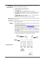
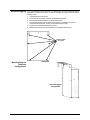
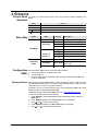
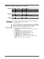
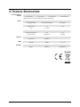
User Manual TABLE OF CONTENTS 1. Before You Begin ...........................................................................................................3 What Is Included ......................................................................................................................... 3 Unpacking Instructions ................................................................................................................ 3 Claims ................................................................................................................................................. 3 Text Conventions ........................................................................................................................ 3 Symbols ...................................................................................................................................... 3 Disclaimer ................................................................................................................................... 3 Product at a Glance..................................................................................................................... 4 Safety Notes ............................................................................................................................... 4 2. Introduction ....................................................................................................................5 Overview ..................................................................................................................................... 5 Dimensions ................................................................................................................................. 6 3. Setup ...............................................................................................................................7 AC Power .................................................................................................................................... 7 Fuse Replacement ............................................................................................................................... 7 Dimmer/Switch Operation ............................................................................................................ 7 Dimmer or Switch Mode .............................................................................................................. 8 Mounting ..................................................................................................................................... 8 Orientation ........................................................................................................................................... 8 Rigging ................................................................................................................................................ 8 Alternate Rigging ................................................................................................................................. 9 4. Operation ......................................................................................................................10 Control Panel Operation ............................................................................................................ 10 Menu Map ................................................................................................................................. 10 Configuration (DMX).................................................................................................................. 10 Starting Address ................................................................................................................................ 10 DMX Channel Modes, Assignments, and Values ....................................................................... 11 4-Channel .......................................................................................................................................... 11 2-Channel .......................................................................................................................................... 11 1-Channel .......................................................................................................................................... 11 Configuration (Standalone) ........................................................................................................ 11 Automatic Mode ................................................................................................................................. 11 5. Technical Information ..................................................................................................12 Product Maintenance ................................................................................................................ 12 6. Technical Specifications ..............................................................................................13 Returns ..................................................................................................................................... 14 Contact Us ................................................................................................................................ 14 Page 2 of 14 DMX-4 User Manual (Rev. 2) 1. BEFORE YOU BEGIN What Is Included • • • • DMX-4 Power Cord Warranty Card Quick Reference Guide Unpacking Instructions Carefully unpack the product immediately and check the container to make sure all the parts are in the package and are in good condition. Claims If the box or the contents (the product and included accessories) appear damaged from shipping, or show signs of mishandling, notify the carrier immediately, not CHAUVET®. Failure to report damage to the carrier immediately may invalidate your claim. In addition, keep the box and contents for inspection. For other issues, such as missing components or parts, damage not related to shipping, or concealed damage, file a claim with CHAUVET® within 7 days of delivery. Text Conventions Symbols Convention [10] 1–512 50/60 Settings Menu > Settings <ENTER> ON Symbol Meaning A DIP switch to be configured A range of values A set of values of which only one can be chosen A menu option not to be modified A sequence of menu options to be followed A key to be pressed on the product’s control panel A value to be entered or selected Meaning Critical installation, configuration, or operation information. Not following these instructions may make the product not work, cause damage to the product, or cause harm to the operator. Important installation or configuration information. The product may not function correctly if this information is not used. Useful information. Disclaimer DMX-4 User Manual (Rev. 2) The information and specifications contained in this User Manual are subject to change without notice. CHAUVET® assumes no responsibility or liability for any errors or omissions, and reserves the right to revise or recreate this manual at any time. Download the latest version from www.chauvetlighting.com. © Copyright 2012 CHAUVET®. All rights reserved. Printed in P.R.C. Electronically published by CHAUVET® in the United States of America. Author Date Editor Date A. Leon 11/12/12 S. Diaz 11/12/12 Page 3 of 14 Product at a Glance Use on Dimmer Outdoor Use Sound-Activated DMX Master/Slave Safety Notes Auto Programs Auto-ranging Power Supply Replaceable Fuse User-Serviceable Duty Cycle These notes include important information about the mounting, usage, and maintenance of this product; read before using the product. • • • • • • • • • • • • • • • • • • Page 4 of 14 Always connect the product to a grounded circuit to avoid the risk of electrocution. Always disconnect the product from the power source before cleaning or replacing the fuse. Make sure the power cord is not crimped or damaged. Never disconnect the product from power by pulling or tugging on the cord. If mounting the product overhead, always secure to a fastening device using a safety cable. Make sure there are no flammable materials close to the product when operating. Always make sure that the voltage of the outlet to which you are connecting the product is within the range stated on the decal or rear panel of the product. The product is for indoor use only! (IP20) To prevent risk of fire or shock, do not expose the product to rain or moisture. Always install the product in a location with adequate ventilation, at least 20 in (50 cm) from adjacent surfaces. Be sure that no ventilation slots on the product’s housing are blocked. Never connect the product to a dimmer. Make sure to replace the fuse with another of the same type and rating. Never carry the product from the power cord. Always use the hanging/mounting bracket. The maximum ambient temperature (Ta) is 104° F (40° C). Do not operate the product at higher temperatures. In the event of a serious operating problem, stop using the product immediately. Never try to repair the product. Repairs carried out by unskilled people can lead to damage or malfunction. Contact the nearest authorized technical assistance center. This product is not intended for permanent installation. Keep this User Manual for future use. If you sell the product to another user, be sure to give this document to the next owner. DMX-4 User Manual (Rev. 2) 2. INTRODUCTION Overview Channel Outputs (1–4) LED Channel Indicators LED Display Control Buttons Power In Power Switch Fuse holders (1–4) DMX-4 User Manual (Rev. 2) DMX In DMX Out Page 5 of 14 Dimensions 7.7 in 194 mm 8.3 in 210 mm 2.8 in 70 mm Page 6 of 14 DMX-4 User Manual (Rev. 2) 3. SETUP AC Power The DMX-4 has an auto-ranging power supply and it can work with an input voltage range of 100–240 VAC, 50/60 Hz. To determine the product’s power requirements (circuit breaker, power outlet, and wiring), use the current value listed on the label affixed to the product’s back panel, or refer to the product’s specifications chart. The listed current rating indicates the product’s average current draw under normal conditions. Always connect the product to a protected circuit (circuit breaker or fuse). Make sure the product has an appropriate electrical ground to avoid the risk of electrocution or fire. Never connect the product to a rheostat (variable resistor) or dimmer circuit, even if the rheostat or dimmer channel serves only as a 0–100% switch. Fuse Replacement Disconnect the product from power before replacing the fuse. 1. 2. 3. 4. 5. Disconnect the product from power. With a #2 Phillips-head screwdriver, unscrew the fuse holder cap from the housing. Remove the blown fuse. Replace with a fuse of the same type and rating. Screw the fuse holder cap back in place and reconnect power. Always replace a blown fuse with another of the same type and rating. Dimmer/Switch Operation Dimmer/switch packs are primarily intended for lamp-based PAR cans. Connecting a fixture equipped with an electronic (switching) power supply to a dimmer/switch pack may damage the fixture or make it work erratically. The improved DMX-4’s design now allows you to switch on and off loads equipped with electronic power supplies, such as LED-based luminaries or laser fixtures. However, the DMX-4 must be in Switch mode before connecting loads of this type to it. Please see the instructions on how to set the DMX-4 in Switch mode below. Always make sure that the DMX-4 is in Switch mode before connecting a load equipped with an electronic power supply to it. Doing otherwise could damage the load. The DMX-4 is optimized to also operate with LED-based products. DMX-4 User Manual (Rev. 2) Page 7 of 14 Dimmer or Switch Mode The DMX-4 has two different methods for controlling the output of the four channels. To set this via the control panel, do the following. 1. 2. 3. 4. 5. 6. 7. Unplug any units from the four output channels. Connect the DMX-4 to a suitable power outlet. Turn the product on. Press <MODE> repeatedly until A001–A512 appears on the display. Press <MENU> repeatedly until S1__, S2__, S3__, or S4__ appears on the display. This setting can be set differently for each of the four channels. Navigate to the desired channel. Use <> or <> to select either __oN (Switch mode) or __oF (Dimmer mode) for the channel selected in the previous step. Repeat steps 5 and 6 to set each of the other channels, if necessary. Mounting Before mounting the product, read and follow the safety recommendations indicated in the Safety Notes. Orientation The DMX-4 may be mounted in any position; however, make sure adequate ventilation is provided around the product. Rigging • Before deciding on a location, always make sure there is easy access to the product for maintenance and programming. • Make sure that the structure or surface onto which you are mounting the product can support the product’s weight (see the Technical Specifications). • When mounting the product overhead, always use a safety cable. Mount the product securely to a rigging point, such as an elevated platform or a truss. • When rigging the product onto a truss, you should use a mounting clamp of appropriate weight capacity. The bracket has 13-mm holes, which are appropriate for this purpose. • The mounting bracket allows for surface mounting. When mounting the product on the floor, make sure that the product and cables are away from people and vehicles. • The back plate may be reversed for an alternate rigging configuration. Mounting Clamp Safety Cable Mounting Bracket Mounting Diagram Page 8 of 14 DMX-4 User Manual (Rev. 2) Alternate Rigging If you are using this product with truss or a lighting stand, there is an alternate rigging configuration available. This option is ideal for hanging the product without using a mounting clamp. 1. Unplug the product from power. 2. On the back of the product, locate the six Phillips-head screws. 3. Use a Phillips-head screwdriver to remove these screws. 4. 5. 6. The mounting bracket will now come off. Be careful not to damage the internal components of the dimmer, as they are exposed during this step! Flip the mounting bracket (back panel) around. Reattach the panel by securely reinstalling the six Phillips-head screws. Remove these six screws Mounting Diagram (Alternate Configuration) Back Panel Alternate Rigging Configuration DMX-4 User Manual (Rev. 2) Page 9 of 14 4. OPERATION Control Panel Operation To access the control panel functions, use the four buttons located underneath the display. Button Function <MODE> Selects an operation mode or backs out of the current menu option <MENU> Selects a menu option <> (UP) Scrolls up the list of options or selects a higher value <> (DOWN) Mode Menu Map Scrolls down the list of options or selects a lower value Menu Display Starting Address A001–A512 Personality DMX Mode Configuration (DMX) Starting Address Set 1. 2. 3. 1-Channel mode CH:02 2-Channel mode CH:04 4-Channel mode S1__ Channel 1 function Channel 2 function Switch: oN Dimmer: oF S3__ Channel 3 function S4__ Channel 4 function Program P:01–P:16 Run Speed SP:01–SP:99 Dimmer d000–d100 Automatic programs Automatic program speeds Slow to fast 0–100% the product in DMX mode to control with a DMX controller. Connect the product to a suitable power outlet. Turn the product on. Connect a DMX cable from the DMX output of the DMX controller to the DMX input socket on the product. When selecting a starting DMX address, always consider the number of DMX channels the selected DMX mode uses. If you choose a starting address that is too high, you could restrict the access to some of the product’s channels. The DMX-4 uses up to 4 DMX channels in the 4-Channel personality DMX mode, which defines the highest configurable address to 509. If unfamiliar with DMX, download the DMX Primer from www.chauvetlighting.com. To select the starting address, do the following: 1. 2. 3. 4. 5. Page 10 of 14 Selects the DMX starting address CH:01 S2__ Switch/Dimmer Standalone Mode Description Press <MODE> to switch between DMX mode and Standalone mode. Switch it to DMX mode. Press <MENU> repeatedly until CH:01–CH:04 shows on the display. Use <> or <> to select the personality. Press <MENU> repeatedly until A001–A512 shows on the display. Use <> or <> to select the starting address. DMX-4 User Manual (Rev. 2) DMX Channel Modes, Assignments, and Values 4-Channel Channel 1 2 3 4 2-Channel Channel 1 2 1-Channel Channel 1 Configuration (Standalone) Function Dimmer Dimmer Dimmer Dimmer Function Dimmer Dimmer Function Dimmer Value 000 000 000 000 255 255 255 255 Value Setting 0–100% 0–100% 0–100% 0–100% Setting 000 255 Channels 1 + 2, 0–100% 000 255 Channels 3 + 4, 0–100% Value Setting 000 255 All four channels, 0–100% Set the product in the standalone Automatic mode to control without a DMX controller. 1. Connect the product to a suitable power outlet. 2. Turn the product on. Never connect a product that is operating in Standalone mode to a DMX string connected to a DMX controller. Products in Standalone mode may transmit DMX signals that could interfere with the DMX signals from the controller. Automatic Mode DMX-4 User Manual (Rev. 2) To enable the Automatic mode, follow the instructions below: 1. Press <MODE> to switch between DMX mode and Standalone mode. Switch it to Standalone mode. 2. Press <MENU> repeatedly until P:01–P:16 shows on the display. 3. Use <> or <> to select the desired Automatic program. 4. Press <MENU> repeatedly until SP:01–SP:99 shows on the display. 5. Use <> or <> to select the desired running speed. 6. Press <MENU> repeatedly until d000–d100 shows on the display. 7. Use <> or <> to select the desired dimmer level for the program currently running. NOTE: There is no dimmer function if you select d000. Page 11 of 14 5. TECHNICAL INFORMATION Product Maintenance To maintain optimum performance and minimize wear, clean the product at least twice a month. However, usage and environmental conditions contribute to increased cleaning frequency. To clean the product, follow the instructions below: • Page 12 of 14 Unplug the product from power. • Wait until the product is at room temperature. • Use a vacuum (or dry compressed air) and a soft brush to remove dust collected on the external surfaces and vents. • Clean all external and transparent surfaces with a mild soap solution, ammonia-free glass cleaner or isopropyl alcohol. • Apply the solution directly to a soft, lint-free cotton cloth. • Softly wipe any dirt or grime to the outside edges of the external and transparent surfaces. • Gently polish the external and transparent surfaces until they are free of haze and lint. DMX-4 User Manual (Rev. 2) 6. TECHNICAL SPECIFICATIONS Dimensions and Weight Length Width Height Weight 8.3 in (210 mm) 7.7 in (194 mm) 2.8 in (70 mm) 5.0 lbs (2.2 kg) Note: Dimensions in inches rounded to the nearest decimal digit. Power Thermal DMX Ordering DMX-4 User Manual (Rev. 2) Power Supply Type Range Voltage Selection Switching (internal) 100–240 VAC, 50/60 Hz Auto-ranging Parameter Maximum per Channel Maximum Total Output Current 5A 15 A Fuse F 7 A, 250 V Power I/O US/Worldwide Power input connector IEC UK/Europe IEC Power Cord plug Edison (US) Local plug Maximum External Temp. Cooling System 104° F (40° C) Convection I/O Connectors Connector Type Channel Range 3-pin XLR Sockets 1, 2, or 4 Product Name Item Code UPC Number DMX-4 09080140 781462206277 Page 13 of 14 To return a product or request support: • • • In the U.S., contact CHAUVET® World Headquarters (see below). In the UK or Ireland, contact CHAUVET® Europe Ltd. (see below). In any other country, DO NOT contact CHAUVET®. Contact your distributor. See www.chauvetlighting.com for distributors outside the U.S., United Kingdom, or Ireland. If you live outside the U.S., United Kingdom, or Ireland, contact your distributor of record and follow their instructions on how to return CHAUVET® products to them. Visit our website for contact details. Returns Call the corresponding CHAUVET® Technical Support office and request a Return Merchandise Authorization (RMA) number before shipping the product. Be prepared to provide the model number, serial number, and a brief description of the cause for the return. You must send the merchandise prepaid, in its original box, and with its original packing and accessories. CHAUVET® will not issue call tags. Clearly label the package with the RMA number. CHAUVET® will refuse any product returned without an RMA number. Write the RMA number on a properly affixed label. DO NOT write the RMA number directly on the box. Before sending the product, clearly write the following information on a piece of paper and place it inside the box: • Your name • Your address • Your phone number • The RMA number • A brief description of the problem Be sure to pack the product properly. Any shipping damage resulting from inadequate packaging will be your responsibility. FedEx packing or double-boxing are recommended. CHAUVET® reserves the right to use its own discretion to repair or replace returned product(s). Contact Us World Headquarters CHAUVET® General Information Address: 5200 NW 108th Avenue Sunrise, FL 33351 Voice: (954) 577-4455 Fax: (954) 929-5560 Toll free: (800) 762-1084 Technical Support Voice: (954) 577-4455 (Press 4) Fax: (954) 756-8015 Email: [email protected] World Wide Web www.chauvetlighting.com Page 14 of 14 United Kingdom & Ireland CHAUVET® Europe Ltd. General Information Address: Unit 1C Brookhill Road Industrial Estate Pinxton, Nottingham, UK NG16 6NT Voice: +44 (0)1773 511115 Fax: +44 (0)1773 511110 Technical Support Email: [email protected] World Wide Web www.chauvetlighting.co.uk DMX-4 User Manual (Rev. 2)