1
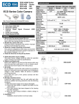
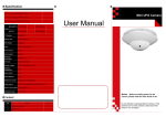
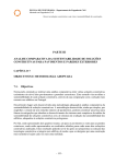
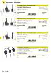
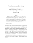
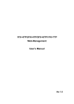
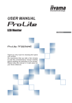
10/07/2006 COVERT PIR CAMERAS INSTRUCTION MANUAL 19 CONTENTS Page Page 1. Description ............................... 1 4. Specifications ........................... 4 2. Installation ................................ 2 5. PIR Detector board installation 3. Wiring instructions ................... 3 and descriptions........................ 5 1. Description Thank you very much for purchasing our product. This B/W (COLOR) HIDDEN CCD Camera uses high sensitive 1/3” (1/4”) interline transfer CCD Image Sensor (CCD = Charge Coupled Device), and all state circuitry which provides extremely long life and high reliability. This Camera offers excellent image quality with low lag and high burn resistance, and is not subject to distortions from magnetic fields. Highly resistance to shock and vibration, and easy to install this Camera is a very good choice for your B/W (COLOR) CCTV system. P.1 2. Installation STEP 1: Secure the bracket to the wall with screws. ( included as shown in Figure 1 ) STEP 2: Attach the Camera Case to the bracket as shown in Figure 2. P.2 STEP 3: Adjust the vertical and horizontal angles by loosening screws (A&B) as in Figure 3 and by turning the bracket vertically and horizontally. A B 3. Wiring instructions STEP 1:Connect the coaxial cable between the camera and the monitor using a 75Ohm coaxial cable. STEP 2: Insert the AC plug into the AC power socket and the DC plug to the DC Jack. Note: AC Adapter Sold separately. P.3 4. Specifications Model Image Pick-up Device Picture Elements (HxV) Horizontal Resolution Minimum Illumination Scanning System Auto Electronic Shutter S / N Ratio Gamma Characteristic Sync System Video Output B/W – PC810/PC810D Colour – PC811/PC811D SONY 1/3” Super HAD CCD sensor SONY 1/4” Super HAD CCD sensor EIA/NTSC: 510x492 CCIR/PAL: 500x582 480 TV lines 420 TV lines 0.3 LUX / F2.0 0.5 LUX / F2.0 Interlace 2 : 1 EIA/NTSC: 1/60s~1/100,000s, CCIR/PAL: 1/50s~1/110,000s. More than 48 dB GAMMA = 0.45 Internal, Negative sync. 1 Vp-p / 75 Ohms. BNC or F connector. 2 Vp-p / 50 Ohms. RCA connector. Audio(Optional) (for model “Audio” & “including PIR working sensor” only) DC 12V ±10% Power Supply Power 1.32W 1.44W Consumption (PIR Sensor not included) Lens Furnished Operating Temp. Built-in PIR Sensor Corn Lens f 3.7mm / F2.0 -10 to 50℃ ( 14 to 122℉) For model including PIR working sensor only. Note: Design and specifications are subject to change without prior notice. P.4 5. PIR Detector board installation and descriptions (for PCC810 & PC811 models only) 6 Output Terminals N.C. N.O. - + 5 Pulse Count PULSE JP2 1 2 4 Light Control Recording Control J2 J1 3 Time Adjustment VR2 VR1 J4 Options A. Top + Center w/black cap: Upon Walk-testing: Light blinking (Disadvantages: Easy to identify as a security system.) J1 (3PINS: Top, Center, Bottom) 2.Sensitivity Adjustment: Low “VR1” 3.Dwell Time Adjustment: Min. 2 Sensitivity Adjustment Description 1.LED Selector: High 1 Led Selector Max. “VR2” Adjustable from 2 to 40 sec. B. Center + Low w/black cap: No light blinking while detecting. (Advantages: less obvious) A. To raise sensitivity: Turn clockwise to detect longer distance and wider pattern. B. To lower sensitivity: Turn counter clockwise for detection in narrow areas. For closure period of N.C/N.O relay connected to an alarm panel, light control or recording control of time lapse VCR, etc. A. Max. time: Turn counter clockwise. B. Min. time: Turn clockwise. Top + Center pins of “J4” must be selected to adjust the time setting. P.5 Options Description 4.Alarm control, Light control or A. Top + Center w/black cap: Operate with “VR2” to adjust Recording control time. (To set the relay output of the Light control or (N.O or N.C) Recording control, the time is selected by individual preference or application. J4 (3PINS: Top, Center, Bottom) B. Center + Bottom w/black jumper: Relay output can be set for Security control panel for only 2 seconds. Note: N.C./N.O. relay output current: 1A 125 VAC, 2A 30 VDC. 5.Pulse Control: Once or twice Position 1: Set to “ONCE” for instant reaction when PIR detects someone: and either the “alarm or Security control panel” or “Recording control” will be triggered immediately. 1 2 J2 4PINS: 2PAIRS w/jumper connector 6.Output Terminals: N.C. N.O. - + JP2 24 Hour/Anti-Tamper 7.Power: 12V DC Standby Current: 3mA, Working Current: 28mA Position 2: Set to “Twice” when PIR detects someone 2 times within 15 seconds. N.C.: Normally Closed A. For connection to: Security panel or Light control CCTV …etc. B. With anti-tamper function for 24 hours. N.O.: Normally Open Contacts ※P.S.: Relay output current: 1A 125VAC, 2A 30V DC Caution: The PIR is triggered by body movement, excluding fixed objects, however, do not place in direct sunlight or reflected sunlight. 100¢X TOP VIEW SIDE VIEW 10 20 30 feet 10 20 30 feet ● Wide angle lens up to 100°, coverage areas to 30x30 feet. ● Provide 64 beams in 3 layers. P.6