1
ZENworks Endpoint Security Management
Version 3.2
Administrator’s Manual
June 14, 2007
© 2007, Novell®, Inc.
All Rights Reserved
The software described in this book is furnished under a license agreement and may be used only in
accordance with the terms of the agreement.
PN: AM300MWE
Document Version 1.0. - supporting Novell ESM 3.2 and subsequent version 3 releases
Legal Notices
Novell, Inc. makes no representations or warranties with respect to the contents or use of this documentation, and specifically disclaims any express or implied warranties of merchantability or fitness for any particular purpose. Further, Novell, Inc. reserves the
right to revise this publication and to make changes to its content, at any time, without obligation to notify any person or entity of
such revisions or changes.
Further, Novell, Inc. makes no representations or warranties with respect to any software, and specifically disclaims any express or
implied warranties of merchantability or fitness for any particular purpose. Further, Novell, Inc. reserves the right to make changes
to any and all parts of Novell software, at any time, without any obligation to notify any person or entity of such changes.
Any products or technical information provided under this Agreement may be subject to U.S. export controls and the trade laws of
other countries. You agree to comply with all export control regulations and to obtain any required licenses or classification to
export, re-export, or import deliverables. You agree not to export or re-export to entities on the current U.S. export exclusion lists
or to any embargoed or terrorist countries as specified in the U.S. export laws. You agree to not use deliverables for prohibited
nuclear, missile, or chemical biological weaponry end uses. See the Novell International Trade Services Web page (http://
www.novell.com/info/exports/) for more information on exporting Novell software. Novell assumes no responsibility for your failure to obtain any necessary export approvals.
Copyright © 2007 Novell, Inc. All rights reserved. No part of this publication may be reproduced, photocopied, stored on a
retrieval system, or transmitted without the express written consent of the publisher. Novell, Inc. has intellectual property rights
relating to technology embodied in the product that is described in this document. In particular, and without limitation, these intellectual property rights may include one or more of the U.S. patents listed on the Novell Legal Patents Web page (http://www.novell.com/company/legal/patents/) and one or more additional patents or pending patent applications in the U.S. and in other
countries.
Novell, Inc.
404 Wyman Street, Suite 500
Waltham, MA 02451
U.S.A.
www.novell.com
Online Documentation: To access the online documentation for this and other Novell products, and to get updates, see the Novell
Documentation Web page (http://www.novell.com/documentation).
Novell Trademarks
For Novell Trademarks, see the Novell Trademark and Service Mark list (http://www.novell.com/company/legal/
trademarks/tmlist.html)
Third-Party Materials
All third-party trademarks are the property of their respective owners.
Licenses
FIPS Certified AES Crypto
Compilation Copyright (c) 1995-2003 by Wei Dai. All rights reserved. This copyright applies only to this software distribution package as a compilation, and does not imply a copyright on any particular file in the package.
The following files are copyrighted by their respective original authors:
mars.cpp - Copyright 1998 Brian Gladman.
All other files in this compilation are placed in the public domain by Wei Dai and other contributors.
Permission to use, copy, modify, and distribute this compilation for any purpose, including commercial applications, is
hereby granted without fee, subject to the following restrictions:
1. Any copy or modification of this compilation in any form, except in object code form as part of an application software, must include the above copyright notice and this license.
2. Users of this software agree that any modification or extension they provide to Wei Dai will be considered public
domain and not copyrighted unless it includes an explicit copyright notice.
3. Wei Dai makes no warranty or representation that the operation of the software in this compilation will be error-free,
and Wei Dai is under no obligation to provide any services, by way of maintenance, update, or otherwise. THE SOFTWARE AND ANY DOCUMENTATION ARE PROVIDED "AS IS" WITHOUT EXPRESS OR IMPLIED WARRANTY
INCLUDING, BUT NOT LIMITED TO, THE IMPLIED WARRANTIES OF MERCHANTABILITY AND FITNESS FOR A
PARTICULAR PURPOSE. IN NO EVENT WILL WEI DAI OR ANY OTHER CONTRIBUTOR BE LIABLE FOR DIRECT,
INCIDENTAL OR CONSEQUENTIAL DAMAGES, EVEN IF ADVISED OF THE POSSIBILITY OF SUCH DAMAGES.
4. Users will not use Wei Dai or any other contributor's name in any publicity or advertising, without prior written consent in each case.
5. Export of this software from the United States may require a specific license from the United States Government. It
is the responsibility of any person or organization contemplating export to obtain such a license before exporting.
6. Certain parts of this software may be protected by patents. It is the users' responsibility to obtain the appropriate
licenses before using those parts.
If this compilation is used in object code form in an application software, acknowledgement of the author is not required
but would be appreciated. The contribution of any useful modifications or extensions to Wei Dai is not required but
would also be appreciated.
Contents
Contents . . . . . . . . . . . . . . . . . . . . . . . . . . . . . . . . . . . . . . . . . . . . . . . . . . . 4
List of Figures . . . . . . . . . . . . . . . . . . . . . . . . . . . . . . . . . . . . . . . . . . . . . . . 6
List of Tables. . . . . . . . . . . . . . . . . . . . . . . . . . . . . . . . . . . . . . . . . . . . . . . . 9
ZENworks Endpoint Security Management . . . . . . . . . . . . . . . . . . . . . . . . 10
ESM Overview . . . . . . . . . . . . . . . . . . . . . . . . . . . . . . . . . . . . . . . . . . . . . . . . . . 11
System Requirements . . . . . . . . . . . . . . . . . . . . . . . . . . . . . . . . . . . . . . . . . . . . 12
About the ESM Manuals . . . . . . . . . . . . . . . . . . . . . . . . . . . . . . . . . . . . . . . . . . . 13
Policy Distribution Service . . . . . . . . . . . . . . . . . . . . . . . . . . . . . . . . . . . . 14
Securing Server Access . . . . . . . . . . . . . . . . . . . . . . . . . . . . . . . . . . . . . . . . . . . 15
Running the Service . . . . . . . . . . . . . . . . . . . . . . . . . . . . . . . . . . . . . . . . . . . . . . 16
Management Service. . . . . . . . . . . . . . . . . . . . . . . . . . . . . . . . . . . . . . . . . 17
Securing Server Access . . . . . . . . . . . . . . . . . . . . . . . . . . . . . . . . . . . . . . . . . . . 18
Running the Service . . . . . . . . . . . . . . . . . . . . . . . . . . . . . . . . . . . . . . . . . . . . . . 19
Management Console . . . . . . . . . . . . . . . . . . . . . . . . . . . . . . . . . . . . . . . . 20
Task Bar . . . . . . . . . . . . . . . . . .
Menu Bar . . . . . . . . . . . . . . . . .
Permissions Settings . . . . . . . . .
Configuration Window . . . . . . . .
Alerts Monitoring . . . . . . . . . . . .
Reporting . . . . . . . . . . . . . . . . .
Generating Custom Reports . . . .
Override-Password Key Generator
USB Drive Scanner. . . . . . . . . . .
.
.
.
.
.
.
.
.
.
.
.
.
.
.
.
.
.
.
.
.
.
.
.
.
.
.
.
.
.
.
.
.
.
.
.
.
.
.
.
.
.
.
.
.
.
.
.
.
.
.
.
.
.
.
.
.
.
.
.
.
.
.
.
.
.
.
.
.
.
.
.
.
.
.
.
.
.
.
.
.
.
.
.
.
.
.
.
.
.
.
.
.
.
.
.
.
.
.
.
.
.
.
.
.
.
.
.
.
.
.
.
.
.
.
.
.
.
.
.
.
.
.
.
.
.
.
.
.
.
.
.
.
.
.
.
.
.
.
.
.
.
.
.
.
.
.
.
.
.
.
.
.
.
.
.
.
.
.
.
.
.
.
.
.
.
.
.
.
.
.
.
.
.
.
.
.
.
.
.
.
.
.
.
.
.
.
.
.
.
.
.
.
.
.
.
.
.
.
.
.
.
.
.
.
.
.
.
.
.
.
.
.
.
.
.
.
.
.
.
.
.
.
.
.
.
.
.
.
.
.
.
.
.
.
.
.
.
.
.
.
.
.
.
.
.
.
.
.
.
.
.
.
.
.
.
.
.
.
.
.
.
.
.
.
.
.
.
.
.
.
.
.
.
.
.
.
.
.
.
.
.
.
.
.
.
.
.
.
.
.
.
.
.
.
.
.
.
.
.
.
.
.
.
.
.
.
.
.
.
.
.
.
.
.
.
.
.
.
.
.
.
.
.
.
20
22
24
28
33
37
47
58
60
Client Location Assurance Service . . . . . . . . . . . . . . . . . . . . . . . . . . . . . . 62
Securing Server Access . . . . . . . . . . . . . . . . . . . . . .
Optional Server Configurations . . . . . . . . . . . . . . . . .
Transferring the Public Key to the Management Service
Updating the Encryption Keys . . . . . . . . . . . . . . . . . .
.
.
.
.
.
.
.
.
.
.
.
.
.
.
.
.
.
.
.
.
.
.
.
.
.
.
.
.
.
.
.
.
.
.
.
.
.
.
.
.
.
.
.
.
.
.
.
.
.
.
.
.
.
.
.
.
.
.
.
.
.
.
.
.
.
.
.
.
.
.
.
.
.
.
.
.
.
.
.
.
.
.
.
.
63
64
64
64
ZENworks Security Client Management . . . . . . . . . . . . . . . . . . . . . . . . . . 65
Client Self Defense. . . . . . . . . . . . . . . . . .
Upgrading the ZSC. . . . . . . . . . . . . . . . . .
Running the ZSC . . . . . . . . . . . . . . . . . . .
ZENworks Security Client Diagnostics Tools
.
.
.
.
.
.
.
.
.
.
.
.
.
.
.
.
.
.
.
.
.
.
.
.
.
.
.
.
.
.
.
.
.
.
.
.
.
.
.
.
.
.
.
.
.
.
.
.
.
.
.
.
.
.
.
.
.
.
.
.
.
.
.
.
.
.
.
.
.
.
.
.
.
.
.
.
.
.
.
.
.
.
.
.
.
.
.
.
.
.
.
.
.
.
.
.
.
.
.
.
.
.
.
.
.
.
.
.
.
.
.
.
.
.
.
.
66
66
67
69
Creating and Distributing ESM Security Policies. . . . . . . . . . . . . . . . . . . . 78
Creating Security Policies . . . . . . . . . . .
Custom User Messages . . . . . . . . . . . . .
Hyperlinks. . . . . . . . . . . . . . . . . . . . . .
Global Policy Settings . . . . . . . . . . . . . .
Wireless Control . . . . . . . . . . . . . . . . .
Global Communication Hardware Control
.
.
.
.
.
.
.
.
.
.
.
.
.
.
.
.
.
.
.
.
.
.
.
.
.
.
.
.
.
.
.
.
.
.
.
.
.
.
.
.
.
.
© 2007 Novell®, Inc.
All Rights Reserved
.
.
.
.
.
.
.
.
.
.
.
.
.
.
.
.
.
.
.
.
.
.
.
.
.
.
.
.
.
.
.
.
.
.
.
.
.
.
.
.
.
.
.
.
.
.
.
.
.
.
.
.
.
.
.
.
.
.
.
.
.
.
.
.
.
.
.
.
.
.
.
.
.
.
.
.
.
.
.
.
.
.
.
.
.
.
.
.
.
.
.
.
.
.
.
.
.
.
.
.
.
.
.
.
.
.
.
.
.
.
.
.
.
.
.
.
.
.
.
.
.
.
.
.
.
.
.
.
.
.
.
.
.
.
.
.
.
.
.
.
.
.
.
.
82
83
84
85
87
89
Storage Device Control . . . . . . . . . . . .
ZSC Update. . . . . . . . . . . . . . . . . . . .
VPN Enforcement . . . . . . . . . . . . . . . .
Locations . . . . . . . . . . . . . . . . . . . . .
Location Settings . . . . . . . . . . . . . . . .
Location Components . . . . . . . . . . . . .
Communication Hardware Settings . . .
Storage Device Control . . . . . . . . . . . .
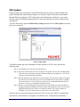
Network Environments . . . . . . . . . . . .
Wi-Fi Management . . . . . . . . . . . . . . .
Wi-Fi Security . . . . . . . . . . . . . . . . . .
Firewall Settings . . . . . . . . . . . . . . . .
TCP/UDP Ports. . . . . . . . . . . . . . . . . .
Access Control Lists . . . . . . . . . . . . . .
Application Controls . . . . . . . . . . . . . .
Integrity and Remediation Rules . . . . .
Antivirus/Spyware Rules . . . . . . . . . . .
Advanced Scripting Rules . . . . . . . . . .
Rule Scripting Parameters. . . . . . . . . .
Sample Scripts . . . . . . . . . . . . . . . . .
Compliance Reporting. . . . . . . . . . . . .
Publishing Security Policies . . . . . . . . .
Exporting a Policy . . . . . . . . . . . . . . .
Importing Policies . . . . . . . . . . . . . . .
Exporting Policies to Unmanaged Users
.
.
.
.
.
.
.
.
.
.
.
.
.
.
.
.
.
.
.
.
.
.
.
.
.
.
.
.
.
.
.
.
.
.
.
.
.
.
.
.
.
.
.
.
.
.
.
.
.
.
.
.
.
.
.
.
.
.
.
.
.
.
.
.
.
.
.
.
.
.
.
.
.
.
.
.
.
.
.
.
.
.
.
.
.
.
.
.
.
.
.
.
.
.
.
.
.
.
.
.
.
.
.
.
.
.
.
.
.
.
.
.
.
.
.
.
.
.
.
.
.
.
.
.
.
.
.
.
.
.
.
.
.
.
.
.
.
.
.
.
.
.
.
.
.
.
.
.
.
.
.
.
.
.
.
.
.
.
.
.
.
.
.
.
.
.
.
.
.
.
.
.
.
.
.
.
.
.
.
.
.
.
.
.
.
.
.
.
.
.
.
.
.
.
.
.
.
.
.
.
.
.
.
.
.
.
.
.
.
.
.
.
.
.
.
.
.
.
.
.
.
.
.
.
.
.
.
.
.
.
.
.
.
.
.
.
.
.
.
.
.
.
.
.
.
.
.
.
.
.
.
.
.
.
.
.
.
.
.
.
.
.
.
.
.
.
.
.
.
.
.
.
.
.
.
.
.
.
.
.
.
.
.
.
.
.
.
.
.
.
.
.
.
.
.
.
.
.
.
.
.
.
.
.
.
.
.
.
.
.
.
.
.
.
.
.
.
.
.
.
.
.
.
.
.
.
.
.
.
.
.
.
.
.
.
.
.
.
.
.
.
.
.
.
.
.
.
.
.
.
.
.
.
.
.
.
.
.
.
.
.
.
.
.
.
.
.
.
.
.
.
.
.
.
.
.
.
.
.
.
.
.
.
.
.
.
.
.
.
.
.
.
.
.
.
.
.
.
.
.
.
.
.
.
.
.
.
.
.
.
.
.
.
.
.
.
.
.
.
.
.
.
.
.
.
.
.
.
.
.
.
.
.
.
.
.
.
.
.
.
.
.
.
.
.
.
.
.
.
.
.
.
.
.
.
.
.
.
.
.
.
.
.
.
.
.
.
.
.
.
.
.
.
.
.
.
.
.
.
.
.
.
.
.
.
.
.
.
.
.
.
.
.
.
.
.
.
.
.
.
.
.
.
.
.
.
.
.
.
.
.
.
.
.
.
.
.
.
.
.
.
.
.
.
.
.
.
.
.
.
.
.
.
.
.
.
.
.
.
.
.
.
.
.
.
.
.
.
.
.
.
.
.
.
.
.
.
.
.
.
.
.
.
.
.
.
.
.
.
.
.
.
.
.
.
.
.
.
.
.
.
.
.
.
.
.
.
.
.
.
.
.
.
.
.
.
.
.
.
.
.
.
.
.
.
.
.
.
.
.
.
.
.
.
.
.
.
.
.
.
.
.
.
.
.
.
.
.
.
.
.
.
.
.
.
.
.
.
.
.
.
.
.
.
.
.
.
.
.
.
.
.
.
.
.
.
.
.
.
.
.
.
.
.
.
.
.
.
.
.
.
.
.
.
.
.
.
.
.
.
.
.
.
.
.
.
.
.
.
.
.
.
.
.
.
.
.
.
.
.
.
.
.
.
.
.
.
.
.
.
.
.
.
.
.
.
.
.
.
.
.
.
.
.
.
.
.
.
.
.
.
.
.
.
.
.
.
.
.
.
.
.
.
.
.
.
.
.
.
.
.
.
.
.
.
.
.
.
.
.
.
.
.
.
.
.
.
.
.
.
.
.
.
.
.
.
.
.
.
90
93
94
98
100
102
103
105
106
109
114
116
118
121
125
128
129
135
138
187
197
199
201
202
203
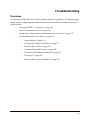
Troubleshooting . . . . . . . . . . . . . . . . . . . . . . . . . . . . . . . . . . . . . . . . . . . 204
Overview . . . . . . . . . . . . . . . . . . . . . . . . . . . . . . . . . . . . . . . . . . . . . . . . . . . . 204
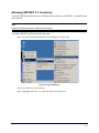
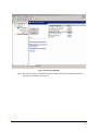
Allowing ASP.NET 1.1 Functions. . . . . . . . . . . . . . . . . . . . . . . . . . . . . . . . . . . . . 205
Troubleshooting SQL Server Issues . . . . . . . . . . . . . . . . . . . . . . . . . . . . . . . . . . 214
Acronym Glossary . . . . . . . . . . . . . . . . . . . . . . . . . . . . . . . . . . . . . . . . . . 234
Index . . . . . . . . . . . . . . . . . . . . . . . . . . . . . . . . . . . . . . . . . . . . . . . . . . . 236
© 2007 Novell®, Inc.
All Rights Reserved
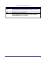
List of Figures
Figure 1: Effectiveness of NDIS-layer firewall . . . . . . . . . . . . . . . . . . . . . . . . . . . . . . . . . . . . . . . . . . . . . . . . . . . . . . 10
Figure 2: ESM Architecture . . . . . . . . . . . . . . . . . . . . . . . . . . . . . . . . . . . . . . . . . . . . . . . . . . . . . . . . . . . . . . . . . . . . . 11
Figure 3: The Management Console . . . . . . . . . . . . . . . . . . . . . . . . . . . . . . . . . . . . . . . . . . . . . . . . . . . . . . . . . . . . . . 20
Figure 4: Menu Bar . . . . . . . . . . . . . . . . . . . . . . . . . . . . . . . . . . . . . . . . . . . . . . . . . . . . . . . . . . . . . . . . . . . . . . . . . . . 22
Figure 5: Management Console Permissions Settings Window . . . . . . . . . . . . . . . . . . . . . . . . . . . . . . . . . . . . . . . . . 25
Figure 6: Permission Settings Organization Table . . . . . . . . . . . . . . . . . . . . . . . . . . . . . . . . . . . . . . . . . . . . . . . . . . . 25
Figure 7: Publish To Settings. . . . . . . . . . . . . . . . . . . . . . . . . . . . . . . . . . . . . . . . . . . . . . . . . . . . . . . . . . . . . . . . . . . . 26
Figure 8: Publish To List . . . . . . . . . . . . . . . . . . . . . . . . . . . . . . . . . . . . . . . . . . . . . . . . . . . . . . . . . . . . . . . . . . . . . . . 27
Figure 9: Infrastructure and Scheduling Window . . . . . . . . . . . . . . . . . . . . . . . . . . . . . . . . . . . . . . . . . . . . . . . . . . . . 28
Figure 10: Authenticating Directories Window. . . . . . . . . . . . . . . . . . . . . . . . . . . . . . . . . . . . . . . . . . . . . . . . . . . . . . 30
Figure 11: Service Synchronization . . . . . . . . . . . . . . . . . . . . . . . . . . . . . . . . . . . . . . . . . . . . . . . . . . . . . . . . . . . . . . . 32
Figure 12: Alerts Dashboard . . . . . . . . . . . . . . . . . . . . . . . . . . . . . . . . . . . . . . . . . . . . . . . . . . . . . . . . . . . . . . . . . . . . 33
Figure 13: Alerts Configuration Tab . . . . . . . . . . . . . . . . . . . . . . . . . . . . . . . . . . . . . . . . . . . . . . . . . . . . . . . . . . . . . . 34
Figure 14: Alert Reporting . . . . . . . . . . . . . . . . . . . . . . . . . . . . . . . . . . . . . . . . . . . . . . . . . . . . . . . . . . . . . . . . . . . . . . 35
Figure 15: Alerts Configuration Tab . . . . . . . . . . . . . . . . . . . . . . . . . . . . . . . . . . . . . . . . . . . . . . . . . . . . . . . . . . . . . . 36
Figure 16: Reports Menu . . . . . . . . . . . . . . . . . . . . . . . . . . . . . . . . . . . . . . . . . . . . . . . . . . . . . . . . . . . . . . . . . . . . . . . 37
Figure 17: Use calendar tool to set the date-range. . . . . . . . . . . . . . . . . . . . . . . . . . . . . . . . . . . . . . . . . . . . . . . . . . . . 37
Figure 18: Report Toolbar . . . . . . . . . . . . . . . . . . . . . . . . . . . . . . . . . . . . . . . . . . . . . . . . . . . . . . . . . . . . . . . . . . . . . . 38
Figure 19: Report list icon . . . . . . . . . . . . . . . . . . . . . . . . . . . . . . . . . . . . . . . . . . . . . . . . . . . . . . . . . . . . . . . . . . . . . . 38
Figure 20: No data . . . . . . . . . . . . . . . . . . . . . . . . . . . . . . . . . . . . . . . . . . . . . . . . . . . . . . . . . . . . . . . . . . . . . . . . . . . . 38
Figure 21: Sample Blocked Applications Report . . . . . . . . . . . . . . . . . . . . . . . . . . . . . . . . . . . . . . . . . . . . . . . . . . . . 41
Figure 22: Sample Location Usage Report . . . . . . . . . . . . . . . . . . . . . . . . . . . . . . . . . . . . . . . . . . . . . . . . . . . . . . . . . 43
Figure 23: Sample Detected Removable Storage Devices report . . . . . . . . . . . . . . . . . . . . . . . . . . . . . . . . . . . . . . . . 44
Figure 24: Sample Wireless Environment History report . . . . . . . . . . . . . . . . . . . . . . . . . . . . . . . . . . . . . . . . . . . . . . 46
Figure 25: Browse the Reporting Data Source . . . . . . . . . . . . . . . . . . . . . . . . . . . . . . . . . . . . . . . . . . . . . . . . . . . . . . 47
Figure 26: Report Document Properties . . . . . . . . . . . . . . . . . . . . . . . . . . . . . . . . . . . . . . . . . . . . . . . . . . . . . . . . . . . 48
Figure 27: Available Database Fields . . . . . . . . . . . . . . . . . . . . . . . . . . . . . . . . . . . . . . . . . . . . . . . . . . . . . . . . . . . . . 48
Figure 28: Add New Crystal Report . . . . . . . . . . . . . . . . . . . . . . . . . . . . . . . . . . . . . . . . . . . . . . . . . . . . . . . . . . . . . . 50
Figure 29: Crystal Reports Wizard . . . . . . . . . . . . . . . . . . . . . . . . . . . . . . . . . . . . . . . . . . . . . . . . . . . . . . . . . . . . . . . 51
Figure 30: Access Reporting Service Database . . . . . . . . . . . . . . . . . . . . . . . . . . . . . . . . . . . . . . . . . . . . . . . . . . . . . . 51
Figure 31: Select OLE DB Provider . . . . . . . . . . . . . . . . . . . . . . . . . . . . . . . . . . . . . . . . . . . . . . . . . . . . . . . . . . . . . . 52
Figure 32: Enter Server Information . . . . . . . . . . . . . . . . . . . . . . . . . . . . . . . . . . . . . . . . . . . . . . . . . . . . . . . . . . . . . . 52
Figure 33: Select Source Table or View . . . . . . . . . . . . . . . . . . . . . . . . . . . . . . . . . . . . . . . . . . . . . . . . . . . . . . . . . . . 53
Figure 34: Select the columns to include . . . . . . . . . . . . . . . . . . . . . . . . . . . . . . . . . . . . . . . . . . . . . . . . . . . . . . . . . . . 53
Figure 35: Select Columns to Group . . . . . . . . . . . . . . . . . . . . . . . . . . . . . . . . . . . . . . . . . . . . . . . . . . . . . . . . . . . . . . 54
Figure 36: Select Style . . . . . . . . . . . . . . . . . . . . . . . . . . . . . . . . . . . . . . . . . . . . . . . . . . . . . . . . . . . . . . . . . . . . . . . . . 54
Figure 37: Visual Basic Report Builder . . . . . . . . . . . . . . . . . . . . . . . . . . . . . . . . . . . . . . . . . . . . . . . . . . . . . . . . . . . . 55
Figure 38: Setting Up a Filter . . . . . . . . . . . . . . . . . . . . . . . . . . . . . . . . . . . . . . . . . . . . . . . . . . . . . . . . . . . . . . . . . . . 55
Figure 39: Create Parameter Field . . . . . . . . . . . . . . . . . . . . . . . . . . . . . . . . . . . . . . . . . . . . . . . . . . . . . . . . . . . . . . . . 56
Figure 40: Link the Parameter . . . . . . . . . . . . . . . . . . . . . . . . . . . . . . . . . . . . . . . . . . . . . . . . . . . . . . . . . . . . . . . . . . . 56
Figure 41: Specify the Correct Records . . . . . . . . . . . . . . . . . . . . . . . . . . . . . . . . . . . . . . . . . . . . . . . . . . . . . . . . . . . . 57
Figure 42: Override Password Key Generator . . . . . . . . . . . . . . . . . . . . . . . . . . . . . . . . . . . . . . . . . . . . . . . . . . . . . . . 58
Figure 43: USB Drive Scanner . . . . . . . . . . . . . . . . . . . . . . . . . . . . . . . . . . . . . . . . . . . . . . . . . . . . . . . . . . . . . . . . . . 60
Figure 44: Scan for Device Name and Serial Number. . . . . . . . . . . . . . . . . . . . . . . . . . . . . . . . . . . . . . . . . . . . . . . . . 61
Figure 45: ZENworks Security Client About Screen. . . . . . . . . . . . . . . . . . . . . . . . . . . . . . . . . . . . . . . . . . . . . . . . . . 70
Figure 46: ZENworks Security Client Diagnostics Screen . . . . . . . . . . . . . . . . . . . . . . . . . . . . . . . . . . . . . . . . . . . . . 70
Figure 47: Administrator Views . . . . . . . . . . . . . . . . . . . . . . . . . . . . . . . . . . . . . . . . . . . . . . . . . . . . . . . . . . . . . . . . . 71
Figure 48: View Policy Window . . . . . . . . . . . . . . . . . . . . . . . . . . . . . . . . . . . . . . . . . . . . . . . . . . . . . . . . . . . . . . . . . 71
Figure 49: Rule Scripting Window . . . . . . . . . . . . . . . . . . . . . . . . . . . . . . . . . . . . . . . . . . . . . . . . . . . . . . . . . . . . . . . 72
Figure 50: Scripting Variable Window . . . . . . . . . . . . . . . . . . . . . . . . . . . . . . . . . . . . . . . . . . . . . . . . . . . . . . . . . . . . 73
Figure 51: Client Driver Status Window . . . . . . . . . . . . . . . . . . . . . . . . . . . . . . . . . . . . . . . . . . . . . . . . . . . . . . . . . . . 73
© 2007 Novell®, Inc.
All Rights Reserved
Figure 52: ZENworks Security Client Settings Control . . . . . . . . . . . . . . . . . . . . . . . . . . . . . . . . . . . . . . . . . . . . . . . 74
Figure 53: Logging Window . . . . . . . . . . . . . . . . . . . . . . . . . . . . . . . . . . . . . . . . . . . . . . . . . . . . . . . . . . . . . . . . . . . . 75
Figure 54: Comment Window . . . . . . . . . . . . . . . . . . . . . . . . . . . . . . . . . . . . . . . . . . . . . . . . . . . . . . . . . . . . . . . . . . . 76
Figure 55: Reporting Overrides . . . . . . . . . . . . . . . . . . . . . . . . . . . . . . . . . . . . . . . . . . . . . . . . . . . . . . . . . . . . . . . . . . 76
Figure 56: Duration Settings, and Make Permanent . . . . . . . . . . . . . . . . . . . . . . . . . . . . . . . . . . . . . . . . . . . . . . . . . . 77
Figure 57: Hold Reports for Diagnostics . . . . . . . . . . . . . . . . . . . . . . . . . . . . . . . . . . . . . . . . . . . . . . . . . . . . . . . . . . . 77
Figure 58: Policy Toolbar . . . . . . . . . . . . . . . . . . . . . . . . . . . . . . . . . . . . . . . . . . . . . . . . . . . . . . . . . . . . . . . . . . . . . . 79
Figure 59: Select Component Window . . . . . . . . . . . . . . . . . . . . . . . . . . . . . . . . . . . . . . . . . . . . . . . . . . . . . . . . . . . . 79
Figure 60: Show Usage Window . . . . . . . . . . . . . . . . . . . . . . . . . . . . . . . . . . . . . . . . . . . . . . . . . . . . . . . . . . . . . . . . . 80
Figure 61: Error Notification Pane. . . . . . . . . . . . . . . . . . . . . . . . . . . . . . . . . . . . . . . . . . . . . . . . . . . . . . . . . . . . . . . . 81
Figure 62: ESM Security Policy creation process . . . . . . . . . . . . . . . . . . . . . . . . . . . . . . . . . . . . . . . . . . . . . . . . . . . . 82
Figure 63: Custom User Message with a Hyperlink . . . . . . . . . . . . . . . . . . . . . . . . . . . . . . . . . . . . . . . . . . . . . . . . . . 83
Figure 64: Custom Message and Hyperlink Controls . . . . . . . . . . . . . . . . . . . . . . . . . . . . . . . . . . . . . . . . . . . . . . . . . 83
Figure 65: Custom User Message with a Hyperlink . . . . . . . . . . . . . . . . . . . . . . . . . . . . . . . . . . . . . . . . . . . . . . . . . . 84
Figure 66: Custom Message and Hyperlink Controls . . . . . . . . . . . . . . . . . . . . . . . . . . . . . . . . . . . . . . . . . . . . . . . . . 84
Figure 67: Global Policy Settings . . . . . . . . . . . . . . . . . . . . . . . . . . . . . . . . . . . . . . . . . . . . . . . . . . . . . . . . . . . . . . . . 85
Figure 68: Updated Policy Custom Message with Hyperlink . . . . . . . . . . . . . . . . . . . . . . . . . . . . . . . . . . . . . . . . . . . 86
Figure 69: Uninstall Password Controls . . . . . . . . . . . . . . . . . . . . . . . . . . . . . . . . . . . . . . . . . . . . . . . . . . . . . . . . . . . 86
Figure 70: Policy Components. . . . . . . . . . . . . . . . . . . . . . . . . . . . . . . . . . . . . . . . . . . . . . . . . . . . . . . . . . . . . . . . . . . 87
Figure 71: Global Communication Hardware Control . . . . . . . . . . . . . . . . . . . . . . . . . . . . . . . . . . . . . . . . . . . . . . . . 89
Figure 72: Global Storage Device Control . . . . . . . . . . . . . . . . . . . . . . . . . . . . . . . . . . . . . . . . . . . . . . . . . . . . . . . . . 90
Figure 73: Verify Local Storage Device Options are set as Disabled . . . . . . . . . . . . . . . . . . . . . . . . . . . . . . . . . . . . . 91
Figure 74: ZSC Update . . . . . . . . . . . . . . . . . . . . . . . . . . . . . . . . . . . . . . . . . . . . . . . . . . . . . . . . . . . . . . . . . . . . . . . . 93
Figure 75: Basic VPN Enforcement. . . . . . . . . . . . . . . . . . . . . . . . . . . . . . . . . . . . . . . . . . . . . . . . . . . . . . . . . . . . . . . 94
Figure 76: Advanced VPN Settings . . . . . . . . . . . . . . . . . . . . . . . . . . . . . . . . . . . . . . . . . . . . . . . . . . . . . . . . . . . . . . . 96
Figure 77: Location Settings . . . . . . . . . . . . . . . . . . . . . . . . . . . . . . . . . . . . . . . . . . . . . . . . . . . . . . . . . . . . . . . . . . . . 98
Figure 78: CLAS location checked . . . . . . . . . . . . . . . . . . . . . . . . . . . . . . . . . . . . . . . . . . . . . . . . . . . . . . . . . . . . . . 101
Figure 79: Location Communication Hardware Control . . . . . . . . . . . . . . . . . . . . . . . . . . . . . . . . . . . . . . . . . . . . . . 103
Figure 80: Location Storage Device Control . . . . . . . . . . . . . . . . . . . . . . . . . . . . . . . . . . . . . . . . . . . . . . . . . . . . . . . 105
Figure 81: Network Environments. . . . . . . . . . . . . . . . . . . . . . . . . . . . . . . . . . . . . . . . . . . . . . . . . . . . . . . . . . . . . . . 106
Figure 82: Wi-Fi Management. . . . . . . . . . . . . . . . . . . . . . . . . . . . . . . . . . . . . . . . . . . . . . . . . . . . . . . . . . . . . . . . . . 109
Figure 83: Managed Access Points Control. . . . . . . . . . . . . . . . . . . . . . . . . . . . . . . . . . . . . . . . . . . . . . . . . . . . . . . . 110
Figure 84: Filtered Access Points Control . . . . . . . . . . . . . . . . . . . . . . . . . . . . . . . . . . . . . . . . . . . . . . . . . . . . . . . . . 111
Figure 85: Prohibited Access Points Control . . . . . . . . . . . . . . . . . . . . . . . . . . . . . . . . . . . . . . . . . . . . . . . . . . . . . . . 111
Figure 86: Signal Strength Control . . . . . . . . . . . . . . . . . . . . . . . . . . . . . . . . . . . . . . . . . . . . . . . . . . . . . . . . . . . . . . 112
Figure 87: Wi-Fi Security . . . . . . . . . . . . . . . . . . . . . . . . . . . . . . . . . . . . . . . . . . . . . . . . . . . . . . . . . . . . . . . . . . . . . 114
Figure 88: Firewall Settings . . . . . . . . . . . . . . . . . . . . . . . . . . . . . . . . . . . . . . . . . . . . . . . . . . . . . . . . . . . . . . . . . . . . 116
Figure 89: TCP/UDP Ports Settings. . . . . . . . . . . . . . . . . . . . . . . . . . . . . . . . . . . . . . . . . . . . . . . . . . . . . . . . . . . . . . 118
Figure 90: Access Control Lists Settings. . . . . . . . . . . . . . . . . . . . . . . . . . . . . . . . . . . . . . . . . . . . . . . . . . . . . . . . . . 121
Figure 91: Application Control Settings . . . . . . . . . . . . . . . . . . . . . . . . . . . . . . . . . . . . . . . . . . . . . . . . . . . . . . . . . . 125
Figure 92: Antivirus/Spyware Integrity rules . . . . . . . . . . . . . . . . . . . . . . . . . . . . . . . . . . . . . . . . . . . . . . . . . . . . . . 129
Figure 93: Integrity Tests . . . . . . . . . . . . . . . . . . . . . . . . . . . . . . . . . . . . . . . . . . . . . . . . . . . . . . . . . . . . . . . . . . . . . . 131
Figure 94: Integrity Checks . . . . . . . . . . . . . . . . . . . . . . . . . . . . . . . . . . . . . . . . . . . . . . . . . . . . . . . . . . . . . . . . . . . . 133
Figure 95: Advanced Scripting . . . . . . . . . . . . . . . . . . . . . . . . . . . . . . . . . . . . . . . . . . . . . . . . . . . . . . . . . . . . . . . . . 135
Figure 96: Script Variables . . . . . . . . . . . . . . . . . . . . . . . . . . . . . . . . . . . . . . . . . . . . . . . . . . . . . . . . . . . . . . . . . . . . 137
Figure 97: Script Text Window . . . . . . . . . . . . . . . . . . . . . . . . . . . . . . . . . . . . . . . . . . . . . . . . . . . . . . . . . . . . . . . . . 194
Figure 98: Compliance Reporting . . . . . . . . . . . . . . . . . . . . . . . . . . . . . . . . . . . . . . . . . . . . . . . . . . . . . . . . . . . . . . . 197
Figure 99: Publish a Security Policy . . . . . . . . . . . . . . . . . . . . . . . . . . . . . . . . . . . . . . . . . . . . . . . . . . . . . . . . . . . . . 199
Figure 100: Open IIS Manager . . . . . . . . . . . . . . . . . . . . . . . . . . . . . . . . . . . . . . . . . . . . . . . . . . . . . . . . . . . . . . . . . 205
Figure 101: Allowing ASP.NET . . . . . . . . . . . . . . . . . . . . . . . . . . . . . . . . . . . . . . . . . . . . . . . . . . . . . . . . . . . . . . . . 206
Figure 102: Communications Console. . . . . . . . . . . . . . . . . . . . . . . . . . . . . . . . . . . . . . . . . . . . . . . . . . . . . . . . . . . . 207
Figure 103: Distribution Service - Client Communication . . . . . . . . . . . . . . . . . . . . . . . . . . . . . . . . . . . . . . . . . . . . 209
Figure 104: Distribution Service - Server Communication . . . . . . . . . . . . . . . . . . . . . . . . . . . . . . . . . . . . . . . . . . . . 210
Figure 105: Management Service - Client Communication . . . . . . . . . . . . . . . . . . . . . . . . . . . . . . . . . . . . . . . . . . . 210
© 2007 Novell®, Inc.
All Rights Reserved
Figure 106: Management Service - Server Communication . . . . . . . . . . . . . . . . . . . . . . . . . . . . . . . . . . . . . . . . . . . 211
Figure 107: Trace Log . . . . . . . . . . . . . . . . . . . . . . . . . . . . . . . . . . . . . . . . . . . . . . . . . . . . . . . . . . . . . . . . . . . . . . . . 212
Figure 108: Add Counters Dialogue Box . . . . . . . . . . . . . . . . . . . . . . . . . . . . . . . . . . . . . . . . . . . . . . . . . . . . . . . . . 214
Figure 109: System Monitor Function . . . . . . . . . . . . . . . . . . . . . . . . . . . . . . . . . . . . . . . . . . . . . . . . . . . . . . . . . . . . 215
Figure 110: Database Tracing . . . . . . . . . . . . . . . . . . . . . . . . . . . . . . . . . . . . . . . . . . . . . . . . . . . . . . . . . . . . . . . . . . 222
Figure 111: Trace Sample . . . . . . . . . . . . . . . . . . . . . . . . . . . . . . . . . . . . . . . . . . . . . . . . . . . . . . . . . . . . . . . . . . . . . 223
Figure 112: Example Configuration Table . . . . . . . . . . . . . . . . . . . . . . . . . . . . . . . . . . . . . . . . . . . . . . . . . . . . . . . . 228
Figure 113: Example Repository Table . . . . . . . . . . . . . . . . . . . . . . . . . . . . . . . . . . . . . . . . . . . . . . . . . . . . . . . . . . . 228
Figure 114: Example Organization Table . . . . . . . . . . . . . . . . . . . . . . . . . . . . . . . . . . . . . . . . . . . . . . . . . . . . . . . . . 229
Figure 115: Example ORG_REP Table . . . . . . . . . . . . . . . . . . . . . . . . . . . . . . . . . . . . . . . . . . . . . . . . . . . . . . . . . . . 229
Figure 116: Example Event Table . . . . . . . . . . . . . . . . . . . . . . . . . . . . . . . . . . . . . . . . . . . . . . . . . . . . . . . . . . . . . . . 230
Figure 117: Example Configuration Table . . . . . . . . . . . . . . . . . . . . . . . . . . . . . . . . . . . . . . . . . . . . . . . . . . . . . . . . 231
Figure 118: Configuration Form . . . . . . . . . . . . . . . . . . . . . . . . . . . . . . . . . . . . . . . . . . . . . . . . . . . . . . . . . . . . . . . . 231
Figure 119: Example Organization Table . . . . . . . . . . . . . . . . . . . . . . . . . . . . . . . . . . . . . . . . . . . . . . . . . . . . . . . . . 232
Figure 120: Organization Audit Table . . . . . . . . . . . . . . . . . . . . . . . . . . . . . . . . . . . . . . . . . . . . . . . . . . . . . . . . . . . . 232
Figure 121: Example Publish_Organization_Audit Table. . . . . . . . . . . . . . . . . . . . . . . . . . . . . . . . . . . . . . . . . . . . . 233
© 2007 Novell®, Inc.
All Rights Reserved
List of Tables
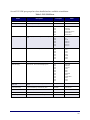
Table 1: System Requirements . . . . . . . . . . . . . . . . . . . . . . . . . . . . . . . . . . . . . . . . . . . . . . . . . . . . . . . . . . . . . . . . . . 12
Table 2: Signal Strength thresholds . . . . . . . . . . . . . . . . . . . . . . . . . . . . . . . . . . . . . . . . . . . . . . . . . . . . . . . . . . . . . . 112
Table 3: TCP/UDP Ports . . . . . . . . . . . . . . . . . . . . . . . . . . . . . . . . . . . . . . . . . . . . . . . . . . . . . . . . . . . . . . . . . . . . . . 120
Table 4: Network Address Macros . . . . . . . . . . . . . . . . . . . . . . . . . . . . . . . . . . . . . . . . . . . . . . . . . . . . . . . . . . . . . . 123
Table 5: Application Controls . . . . . . . . . . . . . . . . . . . . . . . . . . . . . . . . . . . . . . . . . . . . . . . . . . . . . . . . . . . . . . . . . . 126
Table 6: Shell Folder Names . . . . . . . . . . . . . . . . . . . . . . . . . . . . . . . . . . . . . . . . . . . . . . . . . . . . . . . . . . . . . . . . . . . 144
© 2007 Novell®, Inc.
All Rights Reserved
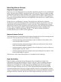
ZENworks Endpoint Security Management
Novell's ZENworks Endpoint Security Management (ESM) provides complete, centralized
security management for all endpoints in the enterprise. Because ESM applies security at the most
vulnerable point, the endpoint, all security settings are applied and enforced regardless of whether
the user is connecting to the network directly, dialing in remotely, or even not connecting to
corporate infrastructure at all. This is critical to not only protect the data within the corporate
perimeter, but also to protect the critical data that resides on the endpoint device itself.
ESM automatically adjusts security settings and user permissions based on the current network
environment characteristics. A sophisticated engine is used to determine the user's location and
automatically adjusts firewall settings and permissions for applications, adapters, hardware, etc.
Security is enforced through the creation and distribution of ESM security policies. Each location
(Work, Home, Alternate, Airport, etc.) listed in a security policy is assigned to a network
environment (or multiple network environments). A location determines which hardware is
available and the degree of firewall settings that are activated within the network environment.
The firewall settings determine which networking ports, access control lists (ACLs), and
applications are accessible/required. Various integrity checks and scripts can be run at location
change to ensure that all required security software is up to date and running.
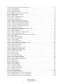
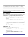
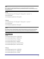
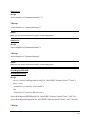
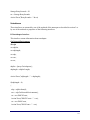
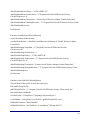
In securing mobile devices, ESM is superior to
typical personal firewall technologies which operate
only in the application layer or as a firewall-hook
driver. ESM client security is integrated into the
Network Driver Interface Specification (NDIS)
driver for each network interface card (NIC),
providing security protection from the moment
traffic enters the PC. Differences between ESM and
application-layer firewalls and filter drivers are
illustrated in Figure 1.
Security decisions and system performance are
optimized when security implementations operate at
the lowest appropriate layer of the protocol stack.
Figure 1: Effectiveness of NDIS-layer firewall
With ESM's ZENworks Security Client, unsolicited
traffic is dropped at the lowest levels of the NDIS driver stack by means of Adaptive Port
Blocking (stateful packet inspection) technology. This approach protects against protocol-based
attacks including unauthorized port scans, SYN Flood, NetBIOS, and DDOS attacks.
10
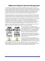
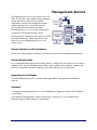
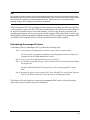
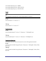
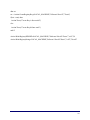
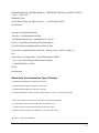
ESM Overview
ESM consists of five high-level functional components: Policy Distribution Service,
Management Service, Management Console, Client Location Assurance Service, and the
ZENworks Security Client. The figure below shows these components in the architecture
Figure 2: ESM Architecture
The ZENworks Security Client (ZSC) is responsible for enforcement of the distributed security
policies on the endpoint system. When the ZSC is installed on all enterprise PCs, these endpoints
may now travel outside the corporate perimeter and maintain their security, while endpoints inside
the perimeter will receive additional security checks within the perimeter firewall.
Each Central Management component is installed separately, the following components are
installed on servers which are secured inside the corporate perimeter:
•
Policy Distribution Service is responsible for the distribution of security policies to
the ZSC, and retrieval of reporting data from the ZSCs. The Policy Distribution
Service can be deployed in the DMZ, outside the enterprise firewall, to ensure regular
policy updates for mobile endpoints
•
Management Service is responsible for user policy assignment and component
authentication; reporting data retrieval, creation and dissemination of ESM reports;
and security policy creation and storage
•
Management Console is a visible user interface, which can run directly on the server
hosting the Management Service or on a workstation residing inside the corporate
firewall with connection to the Management Service server. The Management
Console is used to both configure the Management Service and to create and manage
user and group security policies. Policies can be created, copied, edited, disseminated,
or deleted using the editor
•
Client Location Assurance Service provides a cryptographic guarantee that
ZENworks Security Clients are actually in a defined location, as other existing
network environment parameters indicate
11
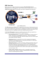
System Requirements
Table 1: System Requirements
Server System Requirements
Endpoint System Requirements
Operating Systems:
Microsoft Windows 2000 Server SP4
Microsoft Windows 2000 Advanced Server SP4
Windows 2003 Server
Operating Systems:
Windows XP SP1
Windows XP SP2
Windows 2000 SP4
Processor:
3.0 GHz Pentium 4 HT (or greater)
756 MB RAM minimum (1 GB+ Recommended)
Processor:
600MHz Pentium 3 (or greater)
Minimum 128 MB RAM (256 MB or greater recommended
Disk Space:
500 MB - Without local Microsoft SQL database
5 GB - With local MS SQL database (SCSI recommended)
Required Software:
Supported RDBMS (SQL Server Standard, SQL
Server Enterprise, Microsoft SQL Server 2000
SP4, or SQL 2005)
Microsoft Internet Information Services (configured for SSL)
Supported Directory Services (eDirectory, Active
Directory, or NT Domains*)
Disk Space:
5 MB required, 5 additional MB recommended for
reporting data
Required Software:
Windows 3.1 Installer
All Windows updates should be current
* = NT Domains is only supported when the Management Service is installed on a Windows 2000, or 2000 advanced server
(SP4).
ASP.NET
The Policy Distribution, Management, and Client Location Assurance services require a LOCAL
account of ASP.NET to be enabled. If this is disabled, the services will NOT work correctly.
Reliable Time Stamp
The Novell ESM solution gathers data from multiple sources and collates this data to create a
wide variety of security and audit reports. The utility and probative value of these reports is
greatly diminished if disparate sources disagree as to times, and so it is strongly recommended
that anyone installing ESM provide for enterprise-wide time synchronization (such as that
provided by Active Directory, or through the use of Network Time Protocol).
The ESM Administrator(s) should follow all installation, operation, and maintenance
recommendations provided in this document and the ESM Installation and Quick-Start
guide, in order to ensure a strong security environment.
12
About the ESM Manuals
The ZENworks Endpoint Security Management manuals provide three levels of guidance for the
users of the product.
•
ESM Administrator's Manual - This guide is written for the ESM Administrators
who are required to manage the ESM services, create security policies for the
enterprise, generate and analyze reporting data, and provide troubleshooting for endusers. Instructions for completing these tasks are provided in this manual
•
ESM Installation and Quick-Start Guide - This guide provides complete installation
instructions for the ESM components and assists the user in getting those components
up and running
•
ZENworks Security Client User's Manual - This manual is written to instruct the
end-user on the operation of the ZENworks Security Client (ZSC). This guide may be
sent to all employees in the enterprise to help them understand how to use the ZSC
13
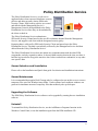
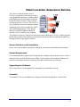
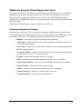
Policy Distribution Service
The Policy Distribution Service is a web service
application that, when requested, distributes security
policies and other necessary data to ZENworks
Security Clients. ESM security policies are created
and edited with the Management Service's
Management Console, then published to the Policy
Distribution Service where they are downloaded by
the client at check-in.
The Policy Distribution Service authenticates
ZENworks Security Clients based on the user ID credentials obtained from the Management
Service, and supplies each client with the designated security policy.
Reporting data is collected by ZENworks Security Clients and passed up to the Policy
Distribution Service. This data is periodically collected by the Management Service and then
deleted from the Policy Distribution Service.
The Policy Distribution Service does not initiate any communications with the other ESM
components, and only responds to others. It does not hold sensitive data in the clear, nor does it
hold the keys needed to decrypt the sensitive data. It does not hold user credentials, or any other
user-specific data.
Server Selection and Installation
Please refer to the Installation and Quick Start guide for selection and installation instructions.
Server Maintenance
It is recommended that regular Disk Cleanup tasks be configured to run on this server to remove
temporary files out of the Windows\temp folder. Under extreme load conditions windows can
generate an inordinate amount of temporary files that needlessly take up disk space.
Upgrading the Software
The ESM Policy Distribution Service software can be upgraded by running the new installation
software.
Uninstall
To uninstall the Policy Distribution Service, use the Add/Remove Programs function in the
Windows Control Panel, or run the installation again from the ESM installation CD.
14
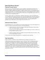
Securing Server Access
Physical Access Control
Physical access to the Distribution Service Server should be controlled to prevent access by
unauthorized parties. Measures taken should be appropriate to the risks involved. There are
multiple available standards and guidelines available, including NIST recommendations, HIPAA
requirements, ISO/IEC 17799, and less formal collections of recommendations such as CISSP or
SANS guidelines. Even when a given regulatory frameworks is not applicable, it may still act as a
valuable resource and planning guide.
Likewise, Disaster Recovery and Business Continuity mechanisms to protect the Distribution
Server should be put in place to protect the server if an organizational risk assessment identifies a
need for such steps. The mechanisms best used will depend on the specifics of the organization
and its desired risk profile, and cannot be described in advance. The same standards and
guidelines sources listed above can be helpful in this decision as well.
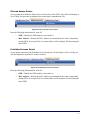
Network Access Control
The Distribution Server can be further protected from unauthorized access by restricting network
access to it. This may take the form of some or all of the following:
•
restricting incoming connection attempts to those ports and protocols from which a
valid access attempt might be expected;
•
restricting outgoing connection attempts to those IP addresses to which a valid access
attempt might be expected; and/or
•
restricting outgoing connection attempts to those ports and protocols to which a valid
access attempt might be expected.
Such measures can be imposed through the use of standard firewall technology.
High Availability
High Availability mechanisms for the Distribution Server should be put in place if an
organizational risk assessment identifies a need for such steps. There are multiple alternative
mechanisms for building high availability solutions, ranging from the general (DNS roundrobining, layer 3 switches, etc.) to the vendor specific (the Microsoft web site has multiple
resources on high availability web services and clustering issues). Those implementing and
maintaining an ESM solution should determine which class of high availability solution is most
appropriate for their context. It should be kept in mind that the Distribution Server has been
architected to function in non-high-availability situations, and does not require High Availability
to provide its services.
15
Running the Service
The Policy Distribution Service launches immediately following installation, with no reboot of
the server required. The Management Console can adjust upload times for the Distribution
Service using the Configuration feature (See “Infrastructure and Scheduling” on page 28). For
other monitoring capabilities see:
•
“Server Communication Checks” on page 207
•
“System Monitor” on page 214
16
Management Service
The Management Service is the central service for
ESM. It is used to create authentication credentials,
design and store security policies and their
components, and provide remediation through a
robust reporting service. It provides security
policies and user information to the Policy
Distribution Service, as well as providing opaque
credentials to ZENworks Security Clients.
Security policies, credentials, and reports are stored
in an SQL database(s), which may reside on the
same server as the Management Service or on
remote servers.
Server Selection and Installation
Please refer to the Installation and Quick Start guide for selection and installation instructions.
Server Maintenance
It is recommended that regular Disk Cleanup tasks be configured to run on this server to remove
temporary files out of the Windows\temp folder. Under extreme load conditions windows can
generate an inordinate amount of temporary files that needlessly take up disk space.
Upgrading the Software
The ESM Management Service software can be upgraded by running the new installation
software.
Uninstall
To uninstall the Management Service, use the Add/Remove Programs function in the Windows
Control Panel.
To uninstall the Management Console (when run on a separate PC), use the Add/Remove
Programs function in the Windows Control Panel.
17
Securing Server Access
Physical Access Control
Physical access to the Management Server should be controlled to prevent access by unauthorized
parties. Measures taken should be appropriate to the risks involved. There are multiple available
standards and guidelines available, including NIST recommendations, HIPAA requirements, ISO/
IEC 17799, and less formal collections of recommendations such as CISSP or SANS guidelines.
Even when a given regulatory frameworks is not applicable, it may still act as a valuable resource
and planning guide.
Disaster Recovery and Business Continuity: Disaster Recovery and Business Continuity
mechanisms to protect the Management Server should be put in place to protect the server if an
organizational risk assessment identifies a need for such steps. The mechanisms best used will
depend on the specifics of the organization and its desired risk profile, and cannot be described in
advance. There are multiple available standards and guidelines available, including NIST
recommendations, HIPAA requirements, ISO/IEC 17799, and less formal collections of
recommendations such as CISSP or SANS guidelines.
Network Access Control
The Management Server can be further protected from unauthorized access by restricting network
access to it. This may take the form of some or all of the following:
•
restricting incoming connection attempts to those IP addresses from which a valid
access attempt might be expected;
•
restricting incoming connection attempts to those ports and protocols from which a
valid access attempt might be expected;
•
restricting outgoing connection attempts to those IP addresses to which a valid access
attempt might be expected; and/or
•
restricting outgoing connection attempts to those ports and protocols to which a valid
access attempt might be expected.
Such measures can be imposed through the use of standard firewall technology.
High Availability
High Availability mechanisms for the Management Server should be put in place if an
organizational risk assessment identifies a need for such steps. There are multiple alternative
mechanisms for building high availability solutions, ranging from the general (DNS roundrobining, layer 3 switches, etc.) to the vendor specific (the Microsoft web site has multiple
resources on high availability web services). Those implementing and maintaining an ESM
solution should determine which class of high availability solution is most appropriate for their
context. It should be kept in mind that the Management Server has been architected to function in
non-high-availability situations, and does not require High Availability to provide its services.
18
Running the Service
The Management Service launches immediately following installation, with no reboot of the
server required. The Management Console is used to manage the data on the Management
Service. See “Infrastructure and Scheduling” on page 28. for more details.
For other monitoring capabilities see:
•
“Server Communication Checks” on page 207
•
“System Monitor” on page 214
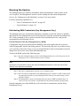
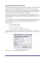
Distributing ESM Credentials (Key Management Key)
The Management Service automatically distributes credentials to each ZSC when it is installed
and checks-in to the Management Service for the first time. Once this credential is distributed, the
ZSC will be permitted to receive policies from the Policy Distribution Service, and provide
reporting data to the Reporting Service.
Periodic Renewal of the Key Management Key (KMK)
Cryptographic best practices dictate that the KMK be renewed at regular intervals to prevent
certain cryptographic attacks from being practical. This need only take place on a relatively long
cycle: typically on the order of once every year, and should not be done too frequently because the
change-over does involve some effort and bandwidth costs.
To renew the KMK, perform the following steps:
Step 1: Open the Communications Console on the Management Service (Start/Programs/Novell/
Management Service/ESM Communications Console).
Note:
Running the Communications Console will cause the Management Service to lose user and log data,
however, policy data will not be deleted.
Step 2: Allow the Communications Console to run a complete check.
Step 3: Have all end-users authenticate to the Management Service (either via VPN or while inside
the appropriate firewall), by right-clicking the ZSC task-tray icon and selecting “Check
for Policy Update.”
Step 4: The Management Console will automatically pass the new KMK credentials down. In
some cases, the user will have to authenticate to the domain (username and password).
Until the endpoints renew their KMK, they will not be able to communicate with the Policy
Distribution Service.
19
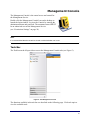
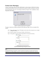
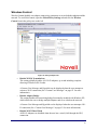
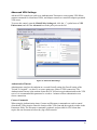
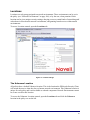
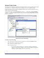
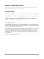
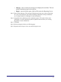
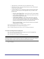
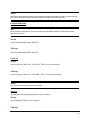
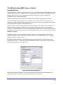
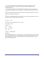
Management Console
The Management Console is the central access and control for
the Management Service.
Double-click the Management Console Icon on the desktop to
launch the login window. Log in to the Console by entering the
administrator name and password. The username entered MUST
be an authorized user on the Management Service
(see “Permissions Settings” on page 24).
Note:
It is recommended that the console be closed or minimized when not in use.
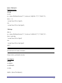
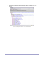
Task Bar
The Task-bar on the left provides access to the Management Console tasks (see Figure 3).
Figure 3: The Management Console
The functions available in the task bar are described on the following page. Click each topic to
view the available tools.
20
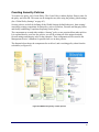
Policy Tasks
The Primary function of the Management Console is the creation and dissemination of Security
Policies. The Policy Tasks guide the administrator through creating and editing security policies
which are used by the ZENworks Security Client to apply centrally managed security to each
endpoint.
The Policy Tasks are:
•
Active Policies - This displays a list of current policies, which can be reviewed and
edited. Click on the policy to open it
•
Create Policies - This begins the policy creation process (see below)
•
Import Policies - This imports policies created on other Management Services (See
“Importing Policies” on page 202)
Clicking any of the policy tasks will minimize the tasks menu. This can be viewed again by
clicking on the tab on the left side.
See “Creating and Distributing ESM Security Policies” on page 78 to learn about the policy tasks
and how to create and manage security policies.
Resources
The following resources are available to help you:
•
Contact Support - This link will launch a browser, and take you to our Support Contact
Page
•
Online Technical Support - This link will launch browser, and take you to our Main
Support Page
•
Management Console Help - Launches Help
Configuration
The Management Service Configuration window provides controls for both the ESM server
infrastructure and controls for monitoring additional enterprise directory services. See
“Configuration Window” on page 28 for details. This control is not available when running a
"Stand-Alone" Management Console (see ESM Installation and Quick-Start Guide for details).
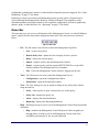
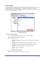
Endpoint Auditing
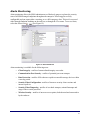
Endpoint Auditing gives you access to ESM Reporting and Alerting.
Alerts monitoring ensures that any attempts to compromise corporate security policies are
reported in the Management Console. This allows the ESM Administrator to know of potential
problems and take any appropriate remedial actions. The Alerts dashboard is completely
21
configurable, granting total control over when and how frequently alerts are triggered. See “Alerts
Monitoring” on page 33 for details.
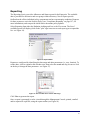
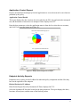
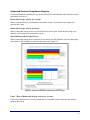
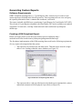
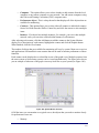
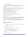
Reporting is critical in assessing and implementing strong security policies. Reports may be
accessed through the Management Console by clicking on Reports. The endpoint security
information gathered and reported back is also completely configurable, and can be gathered by
domain, group, or individual user. See “Reporting” on page 37 for details.
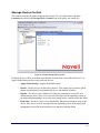
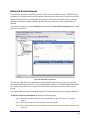
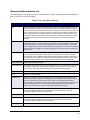
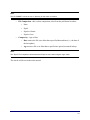
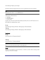
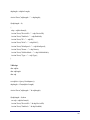
Menu Bar
The menu bar gives you access to all functions of the Management Console. As with all Windows
menus, simply click the menu link to display the menu items. The menu items are described
below. .
Figure 4: Menu Bar
•
•
•
•
File - The File menu is used for the creation and management of policies
•
New - creates a new policy
•
Refresh Policy List - updates the list to display all active policies
•
Delete - deletes the selected policy
•
Import - imports a policy into the Management Console
•
Export - exports a policy and the required SETUP.SEN file to a specified
location outside of the Management Service database
•
Exit - Closes the Management Console software, logging out the user
Tools - The Tools menu is used to control the Management Service
•
Configuration - opens the Configuration window
•
Permissions - opens the Permissions window
View - The View menu gives you an option to change to key policy tasks without
using the task bar
•
Policy - when a policy is open, switches the view to that policy
•
Policy List - displays the policy list
•
Alerts - displays the Alerts dashboard
•
Reporting - displays the Reporting dashboard
Help - The Help menu gives you access to the Management Console Help tool and the
About box
•
Help - launches the Management Console Help tool, which can guide you
through policy creation as well as all Management Console tasks (also
available by pressing the F1 key on your keyboard)
22
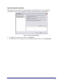
•
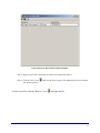
About - launches the About window, which displays the current version of the
Management Console. This is where the license key is entered if purchased
after installation
23
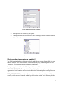
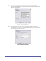
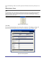
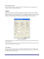
Permissions Settings
This control is found in the Tools menu, and is only accessible by the primary administrator for
the Management Service and/or any whom have been granted "permissions" access by that
administrator. This control is not available when running the "Stand-Alone" Management
Console.
The permissions settings define which user or group of users are permitted access to the
Management Console, Publish Policies, and/or Change Permission Settings.
During the Management Server installation, an administrator or Resource Account name is
entered into the configuration form (see the ESM Installation and Quick-Start Guide). Once a
successful test has been performed and the user information saved, five permissions are
automatically granted to this user (see below).
Once the Management Console is installed, the resource user (defined above) will be the ONLY
user with full permissions, though ALL user groups within the domain will be granted
Management Console Access. The resource user should remove access from all but the groups/
users who should have access. The resource user may set additional permissions for the
designated users. The permissions granted have the following results:
When the Management Console is launched, the permissions are retrieved from the Permission
table. These permissions tell the console whether the user has the rights to log-in to the Console,
Create or Delete policies, change Permissions settings, and whether or not they can Publish
policies, and to whom they are permitted to publish to.
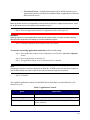
•
Management Console Access: the user may view policies and components, and edit
existing policies. Users granted ONLY this privilege will not be permitted to add or
delete polices; the publish and permissions options will be unavailable
•
Publish Policy: the user may publish policies ONLY to assigned users/groups
•
Change Permission: the user may access and change permissions settings for other
users that have already been defined, or grant permissions to new users
•
Create Policies: the user may create new policies in the Management Console
•
Delete Policies: the user may delete ANY policy in the Management Console
Note:
For security purposes, it is recommended that only the resource user or very FEW administrators be
granted the Change Permission and Delete Policies permissions.
24
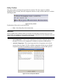
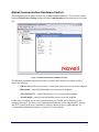
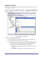
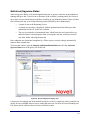
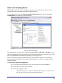
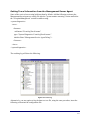
Administrative Permissions
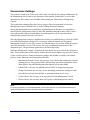
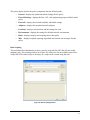
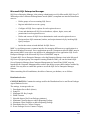
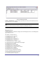
To set the Administrative Permissions, perform the following steps:
Step 1: Open the Tools menu and select Permissions. The groups associated with this domain are
displayed (see Figure 5).
Figure 5: Management Console Permissions Settings Window
Note:
All groups are granted access to the Management Console by default, though they will be unable to
perform policy tasks. Access to the console can be removed by un-checking the permission.
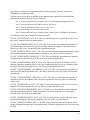
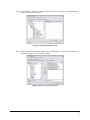
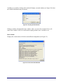
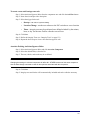
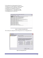
Step 2: To load users/groups to this list, do the following:
a. Click the Add button on the bottom of the screen, the Organization Table will
display (see Figure 6).
Figure 6: Permission Settings Organization Table
25
b. Select the appropriate users/groups from the list. To select multiple users, select
individually by holding down the CTRL key, or select a series by selecting the
top, then holding down the SHIFT key, then selecting the bottom selection.
c. When all users/groups have been selected, click the OK button. This will add the
users/groups to the grid on the Permissions form.
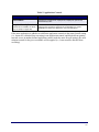
Step 3: Assign any (or all) permissions to the available users/groups.
Step 4: To remove a selected user/group, highlight the name and click Remove. The selected name
will be moved back to Organization Table
.
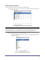
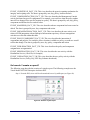
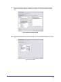
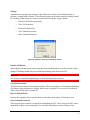
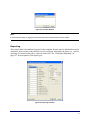
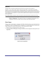
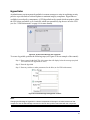
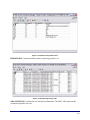
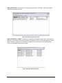
Publish To Settings
Users/Groups who have Publish Policy checked will need to be assigned users and/or groups to
publish to. To set the Publish To Settings, perform the following steps:
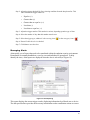
Step 1: Click the Publish Settings tab.
Step 2: Select the users/groups granted the Publish permission from the drop-down list (see Figure
7).
Figure 7: Publish To Settings
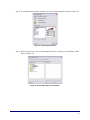
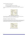
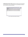
Step 3: Assign users/groups to this user/group by:
a. Click the Add button on the bottom of the screen, the Organization Table will
display.
b. Select the appropriate users/groups from the list. To select multiple users, select
individually by holding down the CTRL key, or select a series by selecting the
top, then holding down the SHIFT key, then selecting the bottom selection.
c. When all users/groups have been selected, click the OK button. This will add the
users/groups to the selected name's publish list (see Figure 8).
26
Figure 8: Publish To List
Step 4: To remove a selected user/group, highlight the name in the list, and click Remove. The
selected name will be moved back to the Organization Table.
The permission sets are immediately implemented, so the administrator only needs to click Close,
and accept the changes to return to the editor.
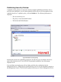
When a new directory service is added (see Managing and Adding Directory Services on page
34), the Resource Account entered is granted full permissions settings, as described above.
27
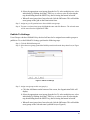
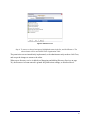
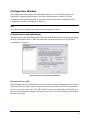
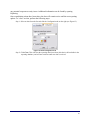
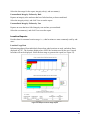
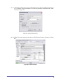
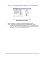
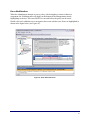
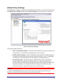
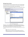
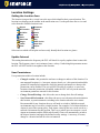
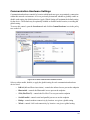
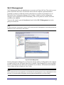
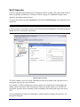
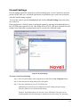
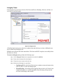
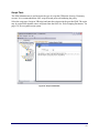
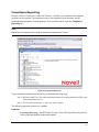
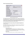
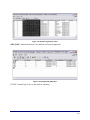
Configuration Window
The Configuration window gives the ESM Administrator access to the Infrastructure and
Scheduling, Authenticating Directories, and Server Synchronization controls. Click the
Configuration link on the main page, or open the Tools menu and select Configuration. The
Configuration window will display (see Figure 9).
Note:
This function is NOT available if this is a Stand-Alone Management Console.
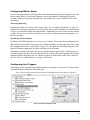
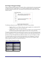
Infrastructure and Scheduling
The infrastructure and scheduling module allows the ESM Administrator to designate and change
the Policy Distribution Service URL and control the synchronization intervals for the ESM
components (see Figure 9).
Figure 9: Infrastructure and Scheduling Window
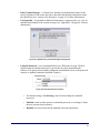
Distribution Service URL
This will update the Policy Distribution Service location for both the Management Service and all
ZENworks Security Clients (without requiring them to be reinstalled) if the Policy Distribution
Service is moved to a new server. The URL for the current server is listed in the text field, only
the server name should be changed to point to the new server. DO NOT change any information
after the server name.
28
Example:
If the current URL is listed as http:\\ACME\PolicyServer\ShieldClient.asmx and the Policy Distribution
Service has been installed on a new server, ACME 43, the URL should be updated as:
http:\\ACME43\PolicyServer\ShieldClient.asmx
Once the URL has been updated, click OK. This will update all policies and send an automatic
update of the Policy Distribution Service. This will also update the Management Service.
When changing the server URL, it is recommended that the old Policy Distribution Service not be
terminated until the updated policies have a 100% adherence level (see Reporting Service).
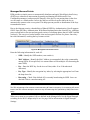
Scheduling
The Scheduling components permit the ESM Administrator to designate when the Management
Service will synchronize with other ESM components, to ensure all data and queued jobs match
any recent activity, and to schedule the SQL maintenance jobs. All time increments are in
minutes.
The scheduling is broken down as follows:
•
Distribution Service - synchronization schedule with the Policy Distribution Service
•
Policy Data and Activity - synchronization schedule with policy updates.
•
Management Data - policy synchronization with the Management Service
•
Enterprise Structure - synchronization schedule with the enterprise directory service
(Active Directory, NT Domain, and/or LDAP). Changes in the enterprise directory
service are monitored so that corresponding changes in user-policy assignments can be
detected and sent to the Policy Distribution Service for Client authentication
•
Client Reporting - frequency the Management Service will interrogate for and
download reporting data from the Policy Distribution Service
•
Keep alert data for: - You can configure alerts based on a snapshot of data reported by
the endpoints. To optimize performance, and ensure that alerts are relevant to recent
activity, you can se the storage threshold based on a number of days.
29
Authenticating Directories
Policies are distributed to end-users by interrogating the Enterprise's existing directory service
(Active Directory, NT Domain*, and/or LDAP). The Authenticating Directories service, is
responsible for handling end-user credentials and authentication issues for the Policy Distribution
Service.
* = NT Domain is only supported when the Management Service is installed on a Windows 2000, or 2000
advanced server (SP4)
Click Authenticating Directories to display the manager.
Managing and Adding Directory Services
An initial directory service is normally detected and monitored during the Management Service
communication check at installation. Authenticating Directories can, if required, manage users
from multiple directories and multiple directory platforms.
Figure 10: Authenticating Directories Window
All information, with the exception of the directory type may be updated. To add a new directory
service, perform the following steps:
Step 1: Click New (located next to Friendly Name)
Step 2: Enter a friendly name for the Directory Service and select its Service Type from the pulldown list
Step 3: In the Host/DN box enter the hostname of a domain controller and leave the Domain/DC
box blank (this box will auto populate after a successful test of the user account in Step 7)
Step 4: Check Available for User Authentication if this is the domain a Management Service is
installed on to display the domain in the login pull-down menu. If this is a separate
domain, leave unchecked
Step 5: Select a Service Connection Option:
30
•
No authentication - login and password not required for connection to
directory service
•
Secure authentication - login and password required for connection to
directory service
•
Read only access - Management Service cannot make updates or changes to
the directory service
•
Bind to specified server - creates a direct connection to the server hosting the
directory service (machine name [netbios] name must be specified in Step 1).
This will increase the speed and efficiency of the connection between the
services
Step 6: Enter the directory service login name under Account and the login password in the
Password field. The login name entered must be a user who has permission to view the
ENTIRE directory tree. It is recommended that this user be either the domain
administrator or an OU administrator
Note:
The password entered should be set to not expire, nor should this account ever be disabled.
Step 7: Click Test to verify communication to this directory service. If communication cannot be
established, the user is notified of the error. Any inaccurate information will be corrected
(when possible) by the interface during the test
Step 8: Click Save to update or add a directory service. Click OK or Cancel to exit the
Configuration window and return to the login screen.
Step 9: Click OK or Cancel to exit the Configuration window and return to the Mangement
Console.
31
Service Synchronization
This control lets you to force a synchronization of the Management Service and Policy
Distribution Service. This will update all alerting, reporting and policy distribution.
Figure 11: Service Synchronization
1. To update the current service status, click Refresh.
2. To restart the services and process the currently queued activities, click Synchronize.
32
Alerts Monitoring
Alerts monitoring allows the ESM Administrator to effortlessly gauge at a glance the security
state of all ESM managed endpoints throughout the enterprise. Alerts triggers are fully
configurable and can report either a warning, or as a full emergency alert. This tool is accessed
either through Endpoint Auditing on the task bar, or through the View menu. To access Alerts,
select the Alerts icon (
) (see Figure 12).
Figure 12: Alerts Dashboard
Alerts monitoring is available for the following areas:
•
Client Integrity - notifies of unremediated integrity test results
•
Communication Port Security - notifies of potential port scan attempts
•
Data Protection - notifies of files that are copied to removable storage devices within
a one day period
•
Security Client Configuration - notifies of incorrect security client versions and
incorrect policies
•
Security Client Tampering - notifies of user hack attempts, uninstall attempts and
usage of the override password
•
Wireless Security - notifies of unsecure access points, both detected and connected to
by the end-user
33
Configuring ESM for Alerts
Alerts monitoring requires reporting data be collected and uploaded at regular intervals to give the
most accurate picture of the current endpoint security environment. Unmanaged ZENworks
Security Clients do not provide reporting data, and will therefore not be included in the Alerts
monitoring.
Activating Reporting
Reporting should be activated in each security policy. See “Compliance Reporting” on page 197
for details on setting up reporting for a security policy. Adjust report send times to an interval that
will give you consistent updates on endpoint status. Additionally, an alert will not activate without
a report. Any activity you wish to be alerted to, must have an appropriate report assigned to it in
the security policy.
Optimizing Synchronization
By default, the ESM Reporting service syncs every 12 hours. This means that reporting and alerts
data will not be ready until 12 hours have passed from installation. To adjust this time frame, open
the Configuration tool (see “Scheduling” on page 29), and adjust the Client Reporting time to the
number of minutes appropriate for your needs and your environment.
When data is needed immediately, the Service Synchronization option in the Configuration tool
can immediately lynch the Policy Distribution Service (which collects the reporting data from the
endpoints) and the Reporting Service, which will update all alerts based on the newly collected
data. See “Service Synchronization” on page 32 for details.
Configuring Alert Triggers
Alert triggers can be adjusted to thresholds that fit your corporate security needs. To adjust alerts
from their defaults, perform the following steps:
Step 1: Select an alert from the list and click the Configuration tab on the right (see Figure 13).
Figure 13: Alerts Configuration Tab
34
Step 2: Adjust the trigger threshold by first, selecting condition from the drop down list. This
states whether the trigger number is:
•
Equal to (=)
•
Greater than (<)
•
Greater than or equal to (<=)
•
Less than (>)
•
Less than or equal to (>=)
Step 3: Adjust the trigger number. This number is variant, depending upon the type of alert.
Step 4: Select the number of days that this number must be met.
Step 5: Select the trigger type, whether it’s the warning icon (
) or the emergency icon (
).
Step 6: Ensure Enable this alert is checked.
Step 7: Click Save to save the alert.
Managing Alerts
Alerts notify you of issues that need to be remediated within the endpoint security environment.
Remediation is normally handled on a case-by-case and individual or group basis. To help
identify the issue, Alert reports are displayed when the alert is selected (see Figure 14).
Figure 14: Alert Reporting
This report displays the current trigger results, displaying information by affected user or device.
The data provided here provides the necessary information to take remediation actions to correct
35
any potential corporate security issues. Additional information can be found by opening
Reporting.
Once remediation actions have been taken, the alert will remain active until the next reporting
update. To “clear” an alert, perform the following steps:
Step 1: Select an alert from the list and click the Configuration tab on the right (see Figure 15).
Figure 15: Alerts Configuration Tab
Step 2: Click Clear. This will clear the reporting data from Alerts (this data is still available in the
reporting database), and will not reactivate until new data is received.
36
Reporting
The Reporting Service provides Adherence and Status reports for the Enterprise. The available
data is provided for directories and user groups within a directory. Novell reports provide
feedback on the effects individual policy components can have on enterprise endpoints. Requests
for these reports are set in the Security Policy (see “Compliance Reporting” on page 197, for
more information), and can provide useful data to determine policy updates.
Select Reporting from either the Endpoint Auditing task bar, or the View menu. The list of
available reports will display (click on the "plus" sign icons next to each report type to expand the
list - see Figure 16).
Figure 16: Reports Menu
Reports are configured by identifying the date range and other parameters (i.e., user, location). To
set the dates, click to expand to the calendar view, then select the month and day (be sure to click
on the day to change the date parameter - see Figure 17).
Figure 17: Use calendar tool to set the date-range
Click View to generate the report.
Once a report is generated it can be viewed through the Management Console, printed, emailed
and/or exported as a.pdf file, using the report toolbar (see Figure 18).
37
Figure 18: Report Toolbar
When reviewing reports, the arrow buttons will help you navigate through each page of the report.
Reports will typically have charts and graphs on the first page with the gathered data on the
remaining pages, ordered by date and type.
The printer button will print the full report using the default printer for this computer.
The Export button saves the report as a PDF file, Excel spreadsheet, Word document, or RTF file
for distribution.
The Group Tree button will toggle a list of parameters to the side of the report. Select any of these
parameters to “drill-down” further into the report. Click the Group Tree button to close the sidebar.
The magnifying glass button provides a drop-down menu to adjust the current view size.
The binoculars button opens a search window.
When you mouse over a certain parameter, like a user name or device name, for example, the
mouse will change to a magnifying glass. You can double-click on that particular item and display
a new report for just that object. Click the “X” button to close the current view and return to the
original report.
To return to the report list, click the Report List icon above the report window (see Figure 19).
Figure 19: Report list icon
Reports are not available until data has been uploaded from the ZENworks Security Clients. By
default, the ESM Reporting service syncs every 12 hours. This means that reporting and alerts
data will not be ready until 12 hours have passed from installation. To adjust this time frame, open
the Configuration tool (see “Scheduling” on page 29), and adjust the Client Reporting time to the
number of minutes appropriate for your needs and your environment.
Reports that do not have data available will have the “Configure” or “Preview” button grayed out,
with the words No data underneath (see Figure 20).
Figure 20: No data
38
Adherence Reports
Adherence Reports provide compliance information regarding the distribution of security policies
to managed users. A score of 100% adherence indicates that all managed users have "checked in"
and received the current policy.
Endpoint Check-In Adherence
This report gives a summary of the days since check-in by enterprise endpoints, and the age of
their current policy, these numbers are averaged to summarize the report. This report requires no
variables be entered. The report will display the users by name, which policies have been assigned
to them, the days since their last check-in, and the age of their policy.
Endpoint Client Versions
Shows the most recently reported version of the client on each endpoint. Set the date parameters
to generate this report.
Endpoints that Never Checked-In
Lists the user accounts that have registered with the Management Service but have never checked
with the Distribution Service for a policy update. Select one or more groups to generate the report.
Note:
These may be Management Console users that don't have a Security Client installed in their names.
Group Policy Non-Compliance
Shows groups where some users do not have the correct policy. Selections can be made for one or
more groups to generate the report.
Endpoint State History by Machine
This report gives the most recent status (in a given date-range) of ESM-protected endpoints,
grouped by machine name. It displays the logged-on user name, current policy, ESM client
version, and network location. This report requires a range of dates to be entered. The
administrator can drill-down by double-clicking on any entry to see a complete list of status
reports for a particular machine.
Policy Assignment
This report shows which users/groups (accounts) have received the specified policy. Select the
desired policy from the list and click View to run the report.
Endpoint State History by User
This report gives the most recent status (in a given date-range) of ESM-protected endpoints,
grouped by user name. It displays the machine name, current policy, ESM client version, and
network location. This report requires a range of dates to be entered. The administrator can drilldown by double-clicking on any entry to see a complete list of status reports for a particular user.
39
Alert Drill-Down Reports
Additional alert information is available in these drill-down reports. These reports will only
display data when an alert has been triggered. Clearing an alert will also clear the alert report,
however, the data will still be available in a standard report.
Client Tampering Alert Data
Displays instances where a user has made an unauthorized attempt to modify or disable the
ZENworks Security Client.
Files Copied Alert Data
Shows accounts that have copied data to removable storage.
Incorrect Client Version Alert Data
Shows the history of the status of the ZSC Update process.
Incorrect Client Policy Alert Data
Shows users who do not have the correct policy.
Integrity Failures Alert Data
Reports on the history of success/failure client integrity checks.
Override Attempts Alert Data
Instances where client self-defense mechanisms have been administratively overridden, granting
privileged control over the ZENworks Security Client.
Port Scan Alert Data
Shows the number of blocked packets on the number of different ports (a large number of ports
may indicate a port scan occurred).
Uninstall Attempt Alert Data
Users that have attempted to uninstall the ZENworks Security Client.
Unsecure Access Point Alert Data
Unsecured access points detected by the ZENworks Security Client.
Unsecure Access Point Connection Alert Data
Unsecured access points connected to by the ZENworks Security Client.
40
Application Control Report
Reports all unauthorized attempts by blocked applications to access the network or run when not
permitted by the policy.
Application Control Details
This report displays the date, location, the action taken by the ZSC, the application that attempted
run, and the number of times this was attempted. Dates displayed in UTC.
Enter the date parameters, select the application name(s) from the list, select the user accounts,
and click View to run the report (see Figure 21).
Figure 21: Sample Blocked Applications Report
Endpoint Activity Reports
Endpoint activity reports provide feedback for individual policy components and the effect they
have on the operation of the endpoint.
Blocked Packets by IP Address
Block Packet Report filtered by Destination IP. Dates displayed in UTC.
Select the destination IP from the list and set the date parameters. The report displays the dates,
locations, affected ports, and the name of the blocked packets.
41
Blocked Packets by User
Block Packet Report filtered by User. Dates displayed in UTC. The data provided is essentially
the same as Blocked Packets by Destination IP, just broken down by user.
Network Usage Statistics by User
Report of packets sent, received or blocked, and network errors, filtered by end-users. This report
requires a range of dates to be entered. Dates displayed in UTC.
Network Usage Statistics by Adapter Type
Report of packets sent, received or blocked, and network errors filtered by adapter type. This
report requires a range of dates to be entered and the Location. Dates displayed in UTC.
Endpoint Updates Report
Shows the status of the ZSC Update process (see “ZSC Update” on page 93). Dates displayed in
UTC.
Chart Percentage of ZSC Update Failures
Charts the percentage of ZSC Update that have failed (and not been remediated). No parameters
are required to generate this report.
History of ZSC Update Status
Shows the history of the status of the ZSC Update process. Select the date range and click View to
run the report. The report displays which users have checked-in and received the update.
Chart Types of Failed ZSC Updates
Shows ZSC Updates that have failed (and not been remediated). Select the date range and click
View to run the report. The report shows which users have checked-in, but had a failed update
installation.
Client Self Defense Report
ZENworks Security Client Hack Attempts
Reports instances where a user has made an unauthorized attempt to modify or disable the
ZENworks Security Client. Dates displayed in UTC.
Enter the date parameters, and click View to run the report.
Integrity Enforcement Report
Provides reporting for antivirus/anti-spyware integrity results.
Client Integrity History
Reports on the success/failure of client integrity checks. Dates displayed in UTC.
42
Select the date range for the report, integrity rule(s), and user name(s).
Unremediated Integrity Failures by Rule
Reports on integrity rules and tests that have failed and not yet been remediated.
Select the integrity rule(s), and click View to run the report.
Unremediated Integrity Failures by User
Reports on users that have failed integrity tests and not yet remediated.
Select the user names(s), and click View to run the report.
Location Reports
Provides data for common location usage. i.e., what locations are most commonly used by endusers.
Location Usage Data
Information gathered from individual clients about what locations are used, and when. Dates
displayed in UTC. The locations displayed are ONLY the locations used by the user. Unused
locations will not be displayed. Select the date range to generate the report (see Figure 22).
Figure 22: Sample Location Usage Report
43
Outbound Content Compliance Reports
Provides information regarding the use of removable drives and identifies which files have been
uploaded to such drives.
Removable Storage Activity by Account
Shows accounts that have copied data to removable storage. No parameters are required to
generate this report.
Removable Storage Activity by Device
Shows removable storage devices to which files have been copied. Select the date range, user
name(s), and location(s) to generate this report.
Detected Removable Storage Devices
Shows removable storage devices that have been detected on the endpoint. Select the date range,
user name(s), and location(s) to generate this report (see Figure 23).
Figure 23: Sample Detected Removable Storage Devices report
Chart 7 Days of Removable Storage Activity by Account
Chart of accounts that have recently copied data to removable storage. Enter the date range to
generate this report.
44
Administrative Overrides Report
Reports instances where client self-defence mechanisms have been administratively overridden,
granting privileged control over the ZENworks Security Client.
ZENworks Security Client Overrides
This report shows successful override attempts by user and date. Dates displayed in UTC.
Select the user and date range, then click View to run the report.
Endpoint Updates Report
Shows the status of the ZSC Update process (see “ZSC Update” on page 93). Dates displayed in
UTC.
History of ZSC Update Status
Shows the history of the status of the ZSC Update process. Select the date range and click View to
run the report. The report displays which users have checked-in and received the update.
Wireless Enforcement Reports
Provides reports regarding wi-fi environments the endpoint is exposed to.
Wireless Connection Availability
Displays the access points available for connection by policy and location. Includes the channel,
SSID, MAC address and whether or not the AP was encrypted.
Wireless Environment
The Wireless Environment report provides a survey of all detected access points (APs), regardless
of ownership. Includes the frequency, signal strength and whether or not the AP was encrypted.
Dates displayed in UTC. Select the desired locations(s) and the date range to generate this report
(see Figure 24).
45
Figure 24: Sample Wireless Environment History report
46
Generating Custom Reports
Software Requirements
ODBC-compliant reporting tools (i.e., Crystal Reports, Brio, Actuate) may be used to create
custom reports not included in the Novell reports list. These reporting tools can view and query
the reporting information from a common data warehouse, star format.
The reports included with ESM were created using Crystal Reports for Visual Studio .NET (SP2).
This version of Crystal Reports is bundled with Visual Studio .NET and is available as an optional
component. To learn more, visit http://msdn.microsoft.com/vstudio/team/crystalreports/
default.aspx
Creating a ESM Compliant Report
Before you begin, please review the report creation process outlined at: http://
msdn.microsoft.com/vstudio/team/crystalreports/gettingstarted/default.aspx
The first phase implementation of the ESM reporting framework has the following requirements
of every report to be integrated into the system:
•
The report may be based on only one data source. That data source must be a single
table or view residing within the source database (see Figure 25).
Figure 25: Browse the Reporting Data Source
•
The report must have a title specified and saved with the report. Optional title, subject,
author and comments will be displayed if specified (see Figure 26).
47
Figure 26: Report Document Properties
•
The report may not contain any sub-reports.
•
Filtering parameters must be named the same as the target columns within the database
fields of the table or view.
Figure 27: Available Database Fields
What reporting information is available?
The ESM reporting database is designed to closely model the star schema format. What is a star
schema? A single "fact" table containing a compound primary key, with one segment for each
"dimension," and additional columns of additive, numeric facts.
The Reporting Service includes the following two dimension tables:
ORGANIZATION_DIM: The organization table, defining the instances of users, groups,
organizational units, containers and services in a hierarchal relationship. Each row represents one
of these units.
UNIT_MEMBER_DIM: Association of organization units to other organization units. For
example, while a user may be stored within a specific container within Active Directory, he/she
48
may also be a member of an organization unit or security groups. Each row represents a
relationship of organization units.
The data source will need to be defined to the reporting tool, typically for most third-party
applications the following steps may be followed:
Step 1: Define an OLEDB ADO connection to the server hosting the Management Service
Step 2: Select the Microsoft OLE DB Provider for SQL Server
Step 3: Enter the Management Service server as the server
Step 4: Enter the SQL account name and password
Step 5: Enter the Reporting Service database name (default name is STRSDB) as the database
The following views are available for report generation:
EVENT_ACCESSPOINT_FACT_VW: This view describes the access points observed by user,
day, policy, location and access point instance.
EVENT_BLOCKEDPACKETS_FACT_VW: This view describes the summarized instances of
port activity that was blocked due to policy configuration by the endpoint. The information is
logged user, day, policy, location and source/destination ip/port.
EVENT_CLIENTACTIVITY_FACT_VW: This view describes the summarized instances of port
activity at the endpoint. The information is logged user, day, policy, location and device.
EVENT_CLIENTAPPLICATIONS_FACT_VW: This view describes the summarized instances
of application use (duration) by user, day, policy, location and application.
EVENT_CLIENTDEFENSE_HACK_FACT_VW: This view describes the instances of hack
attempts against the endpoint client. Active users, applications and services are included within
the report. The data is grouped by user, day, policy, location and attack result.
EVENT_CLIENTDEFENSE_OVERRIDES_FACT_VW: This view describes the instances of
policy override and the affected devices. The data is grouped by user, day, policy, location and
override type.
EVENT_CLIENTDEFENSE_UNINSTALL_FACT_VW: This view describes the instances of
attempts to remove the endpoint client. The data is grouped by user, day, policy, location and
attack result.
EVENT_CLIENTDEVICE_FACT_VW: This view describes the types of devices in use by an
endpoint. The data is grouped by user, day, policy, location and device type.
EVENT_CLIENTENVIRONMENTS_FACT_VW: This view describes the custom (stamped)
network environments used for location detection. The data is grouped by user, day, policy,
location, device type and environment data.
EVENT_CLIENTINTEGRITY_FACT_VW: This view describes the results of integrity rules
applied at the endpoint. The data is grouped by user, day, policy, location and rule.
EVENT_CLIENTLOCATION_FACT_VW: This view describes the time at location as well as
adapter (configuration and type) used at the location. The data is grouped by user, day, policy and
location.
49
EVENT_CLIENTRULE_FACT_VW: This view describes the generic reporting mechanism for
integrity and scripting rules. The data is grouped by user, day, policy, location and rule.
EVENT_COMPONENTACTION_FACT_VW: This view describes the Management Console
activity performed on specific components. For example, you could see when the policy update
interval was changed for a specific location in a policy. The data is grouped by user, day, policy,
component and defines the new and old value.
EVENT_MANGERIO_FACT_VW: This view describes when a component has been created or
edited. The data is grouped by user, day, component and action.
EVENT_ORGANIZATIONACTION_FACT_VW: This view describes the user activity as it
relates to ESM integration with an Enterprise information repository. All user management
activities are reflected within this table.
EVENT_POLICYCOMPONENT_FACT_VW: This view describes the interaction of
components and policies. For example, when a location is added to a policy, an audit row would
reflect that change. The data is grouped by user, day, policy, component and action.
EVENT_PUBLISHACTION_FACT_VW: This view describes the policy and component
assignment to an organization.
EVENT_SERVERACTION_FACT_VW: This view describes the user activity with the
Distribution Service. (Check In, for example)
EVENT_USERACTION_FACT_VW: This view describes the user policy activity with the
Distribution Service. (Policy, Key, EFS Key, Schema downloads.)
So how do I create a report?
The following steps describe the creation of a simple report. The following example uses the
Visual Studio.NET 2003 Enterprise Architect IDE.
Step 1: From the IDE, select Add New Item and add a new Crystal Report (see Figure 28)
Figure 28: Add New Crystal Report
50
Step 2: The simplest method for this example is to create a report using the wizard (see Figure 29)
Figure 29: Crystal Reports Wizard
Step 3: Define the data source. Access the Management Service reporting service database within
data (see Figure 30)
Figure 30: Access Reporting Service Database
51
Step 4: Using the connection definition wizard (see Figure 31), define an OLEDB ADO
connection to the Reporting Service database. Select the Microsoft OLE DB Provider for
SQL Server and click Next.
Figure 31: Select OLE DB Provider
Step 5: Select the Reporting server. Enter the user id, password, and database name for the
Reporting Service (see Figure 32 - refer to the ESM Installation and Quick-Start Guide for
more information) Click Next then Finish.
Figure 32: Enter Server Information
52
Step 6: Select the source table or view that you will be using for your report by expanding the tree
nodes as shown (see Figure 33)
Figure 33: Select Source Table or View
Step 7: Under the Fields tab, select the table or view columns that you wish to include within your
report (see Figure 34). Click Next to continue
Figure 34: Select the columns to include
53
Step 8: If you are planning to group or summarize your data, click the Group tab and select the
columns you wish to group by as shown (see Figure 35). Click Next or Select the Style
tab.
Figure 35: Select Columns to Group
Step 9: Title the report and select the style (see Figure 36). The report builder displays (see Figure
37)
Figure 36: Select Style
54
Figure 37: Visual Basic Report Builder
Step 10: To set up a filter, right click on the Parameter Fields item in the field explorer and select
New (see Figure 38)
Figure 38: Setting Up a Filter
55
Step 11: The following filter allows you to select multiple users to filter by with the prompting text
of "User Name:" displayed within the UI. Notice, the parameter is named the same as the
column (see Figure 39)
Figure 39: Create Parameter Field
Step 12: Right click on the report and select Report->Edit Selection Formula->Records (see Figure
40)
Figure 40: Link the Parameter
56
Step 13: So, using the new parameter, specify only the records where the field equals the values
selected in the parameter. Select the column and then a comparison (=) and then the
parameter. Type CTRL-S to save the filter
Figure 41: Specify the Correct Records
Step 14: Repeat steps 10-13 for each filter. Edit the design of the report and save.
Step 15: After a custom report is generated, the report can be dropped into the \Program
Files\Novell\Management Service\Reports\Reports\ directory on the Management Service
Server. Once there, the new report will display in the reports list in the Reporting Service
web interface (click Refresh List to display the new reports).
57
Override-Password Key Generator
Productivity interruptions that a user may experience due to restrictions to connectivity; disabled
software execution; or access to removable storage devices are likely caused by the security
policy the ZSC is enforcing. Changing locations or firewall settings will most often lift these
restrictions and restore the interrupted functionality. However, in some cases the restriction could
be implemented in such a way that they are restricted in all locations and/or all firewall settings,
or that the user is unable to make a location or firewall setting change.
When this occurs, the restrictions in the current policy can be lifted via a password override to
allow productivity until the policy can be modified. This feature allows an administrator to set up
password protected override for specified users and functionality, which temporarily permits the
necessary activities.
Password overrides disable the current security policy (restoring the default, All Open policy) for
a pre-defined period of time, once the time-limit has expired, the current or updated policy will be
restored. The password for a policy is set in the security policy's Global Rules settings.
Password override:
•
Overrides application blocking
•
Allows user to change locations
•
Allows user to change firewall settings
•
Overrides hardware control (thumb drivers, CDROM, etc.)
The password entered into the policy should NEVER be issued to an end-user. It is recommended
that the Override-Password Key Generator be used to generate a short-term-use key (see Figure
42).
Figure 42: Override Password Key Generator
To generate an override key, perform the following steps:
58
Step 1: Open the Override-Password Key Generator through Start\All Programs\Novell\ESM
Management Console\Override-Password Generator. The Password Generator will
display. (see Figure 42)
Step 2: Enter the policy password in the Administrator Password field, and confirm it in the next
field
Step 3: Enter the user name the end-user logged-in with
Step 4: Set the amount of time the policy will be disabled
Step 5: Click the Generate Key button to generate an override key
This key can be either read to the end-user during a help-desk call, or it can be copied and pasted
into an email. The end-user will enter the key into their ZSC's Administration window (see ZSC
User's Guide). This key will only be good for that user's policy and ONLY for the specified
amount of time. Once the key has been used, it cannot be used again.
Note:
If the user logs-off or reboots their machine during password override, the password will expire, and a new
one will need to be issued.
If a new policy has been written prior to the time limit expiring, the end-user should be instructed
to “Check for a Policy Update,” rather than clicking the Load Policy button on the ZSC about
box.
59
USB Drive Scanner
An authorized USB device list can be generated and imported into a policy using the optional
USB Drive Scanner tool (included with the installation package). See page 90 for details on
implementing an authorized USB Devices list into a Security Policy.
Figure 43: USB Drive Scanner
To generate an authorized devices list, perform the following steps:
Step 1: Open the USB Drive Scanner application
Note:
This is a separate installation from the Management Service and Management Console. A shortcut to the
tool will display on the desktop.
Step 2: Insert a USB Device into the USB port on the computer. The device MUST have a serial
number
Step 3: Click the "Scan" icon ( ), the name of the device and its serial number will display in the
appropriate fields (see Figure 44)
60
Figure 44: Scan for Device Name and Serial Number
Step 4: Repeat steps 2 and 3 until all devices have been entered into the list
Step 5: Click the "Save" icon (
the list into a policy)
) and save the list (see page 92 for instructions on how to import
To edit a saved file, click the "Browse" icon (
) and open the file.
61
Client Location Assurance Service
The Client Location Assurance Service
(CLAS) is an optional feature that provides a
cryptographically-hardened verification that a
pre-defined network environment, identified
by the ZENworks Security Client's location
verification process, is correct. This service is
only reliable in network environments that are
completely and exclusively under the control
of the ESM Administrator. CLAS should
always be installed behind the enterprise
firewall, yet be accessible to any endpoint.
The ZENworks Security Client uses a fixed port to send a challenge to CLAS. CLAS decrypts the
packet and responds to the challenge, proving that it has the private key matching the public key
forming the heart of the digital certificate.
Server Selection and Installation
Please refer to the Installation and Quick Start guide for selection and installation instructions.
Server Maintenance
It is recommended that regular Disk Cleanup tasks be configured to run on this server to remove
temporary files out of the Windows\temp folder. Under extreme load conditions windows can
generate an inordinate amount of temporary files that needlessly take up disk space.
Upgrading the Software
The CLAS software can be upgraded by running the new installation software.
Uninstall
To uninstall CLAS, use the Add/Remove Programs function in the Windows Control Panel.
62
Securing Server Access
Physical Access Control
Physical access to the CLAS Server should be controlled to prevent access by unauthorized
parties. Measures taken should be appropriate to the risks involved. There are multiple available
standards and guidelines available, including NIST recommendations, HIPAA requirements, ISO/
IEC 17799, and less formal collections of recommendations such as CISSP or SANS guidelines.
Even when a given regulatory frameworks is not applicable, it may still act as a valuable resource
and planning guide.
Likewise, Disaster Recovery and Business Continuity mechanisms to protect the CLAS Server
should be put in place to protect the server if an organizational risk assessment identifies a need
for such steps. This is very simple to do, as the vast majority of the CLAS server configuration is
generated by the default install process, and all that needs to be backed up (and protected
appropriately) is the private key used for the cryptographic challenge-response mechanism. With
this key, the CLAS server can be recreated from the readily-available install files.
Network Access Control
The CLAS Server should be further protected from unauthorized access by restricting network
access to it. At a minimum, it is critical to the functionality of CLAS that network access to the
CLAS server be restricted to hosts that reside on the location-defining network. To repeat, there
should be no connectivity whatsoever to the CLAS server from devices which are not already in
the policy-defined network location that CLAS is providing location assurance for, and any
deviation from this requirement negates all assurance value of CLAS.
Furthermore, network access restrictions should include:
3. all incoming connection attempts should be restricted to HTTP over port 80; and
4. no outgoing connection attempts should be allowed.
All these measures can be imposed through the use of standard firewall technology.
High Availability
High Availability mechanisms for the CLAS Server are strongly recommended. There are
multiple alternative mechanisms for building high availability solutions, ranging from the general
(DNS round-robining, layer 3 switches, etc.) to the vendor specific (the Microsoft web site has
multiple resources on high availability web services). Those implementing and maintaining an
ESM solution should determine which class of high availability solution is most appropriate for
their context.
63
Optional Server Configurations
Multiple CLAS iterations may be installed on servers throughout the enterprise, to either
cryptographically assure additional locations, or to assure that if the primary CLAS server goes
down, the location can still be verified by the ZENworks Security Client.
In the case of the second scenario, the private key is located based on URL, rather than IP address.
Therefore, a block of servers can be set up to share a single URL. CLAS may either be installed
on a single server, then that server's image can be copied to each additional server, or it may be
installed on each server separately, and the private and public keys can be copied over to the other
servers. ALL servers in a URL block MUST have the same private and public keys.
Transferring the Public Key to the Management Service
After installation has completed, the generated public key, which will be transferred via security
policy to the ZSC, is located in the \Program Files\Novell\Novell ESM CLAS directory on the
server. The public key is identified by the filename publickey. This filename can be changed to
any name desired.
The public key file will need to then be copied and transferred to the Management Service
(anywhere on the service), which will allow the Management Console to access and distribute the
key to all ZENworks Security Clients through a security policy.
The public key contains both the matching key information and the CLAS URL information. This
information is imported into the Management Console and sent down through a security policy.
Updating the Encryption Keys
Encryption keys can be periodically updated (recommended) by uninstalling and reinstalling
CLAS. When CLAS is reinstalled, new private and public keys are generated. The public key
should then be transferred to the management service and imported again into the affected
security policies to update all ZENworks Security Clients at their next policy check-in.
64
ZENworks Security Client Management
ESM utilizes an installed client application to enforce
complete security on the endpoint itself. This ZENworks
Security Client (ZSC) protects client data by determining
in real-time the network location of the endpoint, and
based on that location:
•
Implements policy-based filtering of all
incoming and outgoing traffic
•
Implements policy-based control over
hardware use (such as that of WLAN access
points, removable media and network adapters)
•
Validates anti-virus software status
•
Collects security-centric statistics and event traps, and passing that information to
centralized servers for collation and analysis; and
•
Launches nominated applications in policy-defined situations (for example, the policy
is set that in a certain location a VPN program must be used to access the network, that
program is launched by the ZSC)
If the network environment is not recognized, the ZSC sets the location to a default Unknown
location, and applies the Unknown security policy. Security policies are completely configurable
by the ESM Administrator (see Chapter 7). For ZSC operating instructions, see the ESM
ZENworks Security Client User's Guide.
All ZSC security functionality is determined by the security policy.
Prior to Installing the ZENworks Security Client
•
It is recommended ALL anti-virus software be shut down during the installation of the
ZENworks Security Client.
•
Verify all Microsoft security patches and updates are current.
For installation instructions, please see the Installation and Quick Start Guide provided with this
software.
Uninstall
To uninstall the ZENworks Security Client, go to start\programs\Novell\ZENworks Security
Client\uninstall ZENworks Security Client.
You can optionally uninstall by:
1. Running setup.exe with /V”STUNINSTALL=1”
2. Running the following command: msiexec.exe /X {C1773AE3-3A47-48EB-93387FF2CDC73E67} STUNINSTALL=1
65
Note:
To specify the uninstall password you can also pass this MSI Property: STUIP=\”password goes here\”
It is recommended any wireless card be ejected prior to uninstallation, the Wi-Fi radio be
switched-off, and all software with a network connection be closed (i.e.: VPN or FTP software).
Note:
It is recommended that prior to uninstalling the ZENworks Security Client, that a simple policy be
distributed to those clients. Policies which globally disable Wi-Fi functionality, disable any communication
hardware, and/or storage devices can leave that hardware disabled following uninstallation, requiring that
each device be manually re-enabled.
Client Self Defense
The ZSC is protected from being intentionally or unintentionally uninstalled, shutdown, disabled,
or tampered with in any way that would expose sensitive data to unauthorized users. Each
measure protects the client against a specific vulnerability:
•
Normal uninstall is not allowed without an installation password (if implemented, see
ESM Installation and Quick-Start Guide), or an uninstall MSI is pushed down by the
administrator
•
Windows Task Manager requests to terminate STEngine.exe and STUser.exe
processes are disallowed
•
Service Pause/Stop and client uninstall is controlled by password, defined in the policy
•
Critical files and registry entries are protected and monitored. If a change is made to
any of the keys or values that are not valid, the registry its immediately changed back
to valid values
•
NDIS filter driver binding protection. If the NDIS driver is not bound to each adapter,
STEngine will rebind the NDIS filter driver.
Upgrading the ZSC
The ZENworks Security Client may be upgraded in any of three ways:
•
By physically running the new install executable (default name is setup.exe) with the
the STUPGRADE=1 switch activated, on each client machine
•
By running an MSI uninstall of the current ZSC and running a new installation (MSI
CANNOT perform upgrades)
•
By utilizing the ZSC Update option (RECOMMENDED, see “ZSC Update” on
page 93)
66
Setting the Upgrade Switch
Step 1: Open the new installation package for the ZSC and right-click setup.exe.
Step 2: Select Create Shortcut.
Step 3: Right-click the shortcut and select Properties.
Step 4: At the end of the Target field, after the quotes, click the space bar once to enter a space,
then type /V“STUPGRADE=1”
Example: “C:\Documents and Settings\euser\Desktop\CL-Release-3.2.455\setup.exe” /V“STUPGRADE=1”.
Step 5: Click OK.
Step 6: Double-click the shortcut to lauch the upgrade installer.
Running the ZSC
The ZSC will run automatically at system startup. For user operation of the ZSC, see the ZSC
User's Manual.
The User's Manual can be distributed to all users to help them better understand the operation of
their new notebook security software.
Multiple User Support
For machines that have multiple users logging onto them, each user account will have its own,
separate Novell environment - the users can have separate policies and saved network
environments. Each account will need to login to the Management Service separately to receive
its credential in order to download its published policy.
In a case where a user either can't or refuses to login, they will get the initial policy that was
included at ZSC installation. This helps discourage a user from creating a different account to
avoid policy restrictions.
Since only one policy can be enforced at a time, Microsoft's "Fast User Switching" (FUS) is not
supported. The ZSC turns off FUS at installation.
For an unmanaged client, the first policy that is pushed to one of the users will be applied to all
users until the other users drop in their policies.
The users on a single computer must all be managed or unmanaged. If managed, all the users
must use the same Management and Policy Distribution Service.
Machine-Based Policies
The option for using machine-based, rather than user-based policies is set at ZSC installation (see
the ESM Installation and Quick-Start Guide for details). When selected, the machine will be
assigned the policy from the Management Service, and that policy will be applied to ALL users
who log-on to that machine. Users who have a policy assigned to them for use on another machine
will not have that policy transfer over when they log-on to a machine with a machine-based
policy. Rather, the computer-based policy will be enforced.
67
Note:
The machine must be a member of the Policy Distribution Service's domain for the first policy sent down.
Occasionally, Microsoft will not generate the SID immediately, which can prevent the ZSC on that machine
from receiving its credential from the Management Service. When this occurs, reboot the machine
following complete ZSC installation to receive the credentials
When switching an ZSC from accepting user-based policies to accepting machine-based policies,
it will continue to enforce/use the LAST policy downloaded by the current user, until credentials
are provided. If multiple users exist on the machine, it will use only the policy assigned to the
currently logged in user. If a new user logs in, and the computer SID is unavailable, it will use the
default policy included at installation, until the computer SID is available. Once the computer SID
is available for the endpoint, all users will have the machine-based policy applied.
Distributing Unmanaged Policies
To distribute polices to unmanaged ZSCs, perform the following steps:
Step 1: Locate and copy the Management Console's setup.sen file to a separate folder.
The setup.sen file is generated at installation of the Management Console, and placed in
\Program Files\Novell\ESM Management Console\
Step 2: Create a policy in the Management Console (see Chapter 7)
Step 3: Use the Export command (see page 116) to export the policy to the same folder containing
the setup.sen file.
All policies distributed MUST be named policy.sen for an unmanaged ZSC to accept
them.
Step 4: Distribute the policy.sen and setup.sen files. These files MUST be copied to the \Program
Files\Novell\ZENworks Security Client\ directory for all unmanaged clients.
The Setup.sen file only needs to be copied to the unmanaged ZSCs once, with the first policy.
Afterwards, only new policies need to be distributed.
68
ZENworks Security Client Diagnostics Tools
The ZENworks Security Client features several diagnostics tools which can create a customized
diagnostics package which can then be delivered to Novell Technical Support to resolve any
issues. Optionally, logging and reporting can be activated to provide full details regarding
endpoint usage. Administrators can also view the current policy, add rule scripting, and check the
ZSC driver status.
Each function of the diagnostics tools are discussed in detail below.
Creating a Diagnostics Package
If problems occur due to the ZSC’s presence on the endpoint, administrators can provide fullydetailed diagnostics information packages to Novell Technical Support. This information is vital
in resolution of any issues. The diagnostics package is defined by the following items:
•
Bindings - captures the current driver bindings for the endpoint
•
Client Status - captures the current client status (displayed on the About window) as
well as other internal status
•
Driver Status - captures the current status of all drivers on the endpoint (displayed in
the Driver Status window)
•
Group Policy Object - captures the current GPO for the user/endpoint as designated
by your directory service (i.e., Active Directory)
•
Log Files - captures the designated logs (see “ Logging” )
•
Policy - captures the current policy running on the ZSC (see “ View Policy” )
•
Network Environments - captures the current and detected network environments
•
Registry Settings - captures the current registry settings
•
Reports - captures any reports in the temp directory (see “ Reporting” )
•
System Event Logs - captures the current System Event logs
•
System Information - captures all system information
69
To create a diagnostics package, perform the following steps:
Step 1: Right-click on the ZSC icon and select About. The About screen will display (see Figure
45).
Figure 45: ZENworks Security Client About Screen
Step 2: Click Diagnostics. The Diagnostics window will display (see Figure 46).
Figure 46: ZENworks Security Client Diagnostics Screen
Step 3: Select the items to be included in the package (all are checked by default).
Step 4: Click Create Package to generate the package.
Step 5: The generated package (ESSDiagnostics_YYYYMMDD_HHMMSS.zip.enc) will be
available on the desktop. This encrypted zip file can now be sent to Technical Support.
Remove Temporary Files
This setting, ONLY available when password override is active in the policy, can be unchecked to
keep each package component type in a temporary directory. This setting should only be
unchecked when a Novell Professional Services representative is present on-site and wishes to
70
check individual logs. Otherwise, the files generated will unnecessarily take up disk space over
time.
Administrator Views
Note:
The Administrator views, like the Remove Temporary Files check-box, will only display when password
override is present in the policy. The first button will require that either the password or temporary
password be entered. After the password is entered it will not need to be entered again, so long as the
diagnostics window remains open.
Figure 47: Administrator Views
View Policy
The view policy button displays the current policy on the device. The display (see Figure 48)
shows basic policy information and can be used to troubleshoot suspected policy issues.
Figure 48: View Policy Window
71
The policy display divides the policy components into the following tabs:
•
General - displays the global and default settings for the policy
•
Firewall Settings - displays the Port, ACL, and Application groups available in this
policy
•
Firewalls - displays the firewalls and their individual settings
•
Adapters - displays the permitted network adapters
•
Locations - displays each location, and the settings for each
•
Environments - displays the settings for defined network environments
•
Rules - displays integrity and scripting rules in this policy
•
Misc. - displays assigned reporting, hyperlinks and custom user messages for this
policy
Rule Scripting
This tool allows the administrator to enter a specific script into the ZSC that will run on this
endpoint, only. The scripting window (see Figure 49) can browse for an available script (Note:
Scripts MUST be either jscript or vbscript), or a script can be created using this tool.
Figure 49: Rule Scripting Window
72
Variables are created by clicking Add, which will display a second window (see Figure 50) where
the variable information may be entered.
Figure 50: Scripting Variable Window
Editing a variable will launch the same window, where you can edit as needed. Delete will
remove the variable. Click Save on the main scripting window once a variable is set.
Driver Status
Displays the current status of all drivers and affected components (see Figure 51).
Figure 51: Client Driver Status Window
73
Settings
Administrators can adjust the settings for the ZENworks Security Client without having to
perform a reinstall of the software. The following actions can be taken using the Settings control,
by checking off the actions you wish to perform and clicking the “Apply” button:
•
Disable Self Defense (persistent)
•
Clear File Protection
•
Reset to Default Policy
•
Clear Uninstall Password
•
Reset Uninstall Password
Figure 52: ZENworks Security Client Settings Control
Disable Self Defense
When applied, all protections used to keep the client installed and active on the machine will be
disabled. Disabling should only be used when performing patch fixes to the ZSC.
WARNING:
This must be un-checked and applied again, or Client Self Defense will remain off.
Clear File Protection
This will clear the hashes from the protected files. The current policies and licensing information
will remain. Once the hashes are cleared, the file may be updated. This can only be performed
while Client Self Defense is turned off.
Reset to Default Policy
Restores the original policy to permit check-in when the current policy is blocking access.
Clear Uninstall Password
This clears the password that is required for uninstalling the ZSC. Once cleared, the ZSC can be
uninstalled without a password prompt. Use when the uninstall password is failing, or lost.
74
Reset Uninstall Password
Resets the password required to uninstall the ZSC. The administrator will be prompted with a
window to enter the new uninstall password.
Logging
Logging can be turned on for the ZSC, permitting it to log specific system events. The default
logs gathered by the ZSC are XML Validation and Commenting. Additional logs can be selected
from the checklist. When troubleshooting, it is recommended that logging be set according to the
directions of Technical Support and the circumstances that lead to the error be repeated.
Figure 53: Logging Window
Additionally, the type of log created, file settings and roll over settings can be adjusted, based on
your current needs.
To make the new logs record every time, check the Make Permanent box, otherwise the ZSC will
revert to its default logs at the next reboot.
Add Comment
The option to add a comment to the logs is available on the diagnostics window. Click the Add
Comments button, and the add comment window will display (see Figure 54). Comments will be
included with the next batch of logs.
75
Figure 54: Comment Window
Note:
If the Comments option in logging is unchecked, the Add Comments button will not display.
Reporting
This control allows the addition of reports for this endpoint. Reports may be added and increased
in duration, however they cannot fall below what was already assigned by the policy (i.e., specific
reporting, if activated in the policy, cannot be turned off). See “Compliance Reporting” on
page 197. for descriptions of the report types.
Figure 55: Reporting Overrides
76
The duration settings for each report type are:
•
Off - data will not be gathered
•
On - data will be gathered based on the set duration
•
On - Disregard Duration - the data will be gathered indefinitely
The duration and send interval can be set using the Report Times controls on the right of the
screen.
Figure 56: Duration Settings, and Make Permanent
Check the Make Permanent box to continue uploading the new reports for just this end-user,
otherwise reporting will revert to the policy default at the next reboot.
Making Reports Available for a Diagnostics Package
To capture reports in the diagnostics package, check the Hold Files box in the Reporting window.
This will hold reports after uploading in the temp directory for the time/space defined in the
Reporting window. These reports can then be bundled in the diagnostics package.
Figure 57: Hold Reports for Diagnostics
77
Creating and Distributing ESM Security Policies
Security Policies are used by the ZENworks Security Client to apply location security to mobile
users. Decisions on networking port availability, network application availability, file storage
device access, and wired or Wi-Fi connectivity are determined by the administrator for each
location.
Security policies can be custom-created for the enterprise, individual user groups, or individual
users/machines. Security policies can allow full employee productivity while securing the
endpoint, or can restrict the employee to only running certain applications and having only
authorized hardware available to them.
To begin a security policy, click New Policy in the File menu of the Management Console
Policy Tabs and Tree
A security policy is written/edited by navigating through the available tabs at the top of the
screen, and the components tree on the left.
The available tabs are:
•
Global Policy Settings - Settings which are applied as defaults throughout the policy
•
Locations - These policy rules are applied within a specific location type, whether
specified as a single network, or a type of network such as a coffee shop or airport
•
Integrity and Remediation Rules - Assures essential software (such as antivirus and
spyware) is running and up-to-date on the device
•
Compliance Reporting - Instructs whether reporting data (including the type of data) is
gathered for this particular policy
•
Publish -Publishes the completed policy to individual users, directory service user
groups, and/or individual machines.
The Policy Tree displays the available subset components for the tabbed categories. For example,
Global Policy Settings include subsets of Wireless Control, ZSC Update, and VPN Enforcement.
ONLY the items contained on the primary subset page are required to define a category, the
remaining subsets are optional components.
78
Policy Toolbar
The policy toolbar (see Figure 58) provides four controls. The Save control is available
throughout policy creation, while the component controls are only available under the Locations
and Integrity tabs.
Figure 58: Policy Toolbar
Explanations of the tools are provided below:
•
Save - Saves the policy in its current state
IMPORTANT:
As you complete each component subset, it is HIGHLY recommended you click the Save icon on the
Policy toolbar. If incomplete or incorrect data is entered into a component, the error notification screen will
display - see “Error Notification” on page 81 for more details.
•
New Component - Creates a new component in a Location or Integrity subset. Once
the policy is saved, a new component is available to associate in other policies
•
Associate Component - This control opens the Select Component screen for the
current subset (see Figure 59). The available components include any pre-defined
components included at installation, and all components created in other policies.
Figure 59: Select Component Window
79
IMPORTANT:
Changes made to associated components will affect all other instances of that component.
Example: You can create a single Location component named "Work," which defines the corporate
network environment and security settings to be applied whenever an endpoint enters that environment.
This component can now be applied to all security policies. Updates to the environment or security settings
can be changed in the component in one policy and will update the same component in all other policies
that it's associated to.
Use the Show Usage command to view all other policies associated with this component (see below).
•
Remove Component - This control will remove a component from the policy. The
component will still be available for association in this and other policies.
Show Usage
Changes made to shared policy components will affect all policies they are associated with. Prior
to updating or otherwise changing a policy component, it is recommended that you run the Show
Usage command to determine which policies will be affected by the change.
1. Right-click the component and select Show Usage
2. A pop-up window will display, showing each instance of this component in other policies (see
Figure 60).
Figure 60: Show Usage Window
80
Error Notification
When the administrator attempts to save a policy with incomplete or incorrect data in a
component, the Validation pane will display at the bottom of the Management console,
highlighting each error. The errors MUST be corrected before the policy can be saved.
Double-click each validation row to navigate to the screen with the error. Errors are highlighted as
shown in the figure below (see Figure 61).
Figure 61: Error Notification Pane
81
Creating Security Policies
To create a new policy, click Create Policy. The Create Policy window displays. Enter a name for
the policy and click OK. This name can be changed at any time using the primary global settings
(See “Global Policy Settings” on page 85.).
Security policies are built by defining all the Global Settings (default behaviors), then creating/
associating existing components for that policy, such as Locations, Firewalls and Integrity Rules,
and finally establishing Compliance Reporting for the policy.
The components are created either within a “dummy” policy or are associated from other policies.
It is assumed that for your first few policies you will be creating all of the unique locations,
firewall settings and integrity rules for the enterprise. These components will be stored in the
Management Service’s database for possible later use in other policies.
The diagram below shows the components for each level, and a resulting policy taken from the
selections (see Figure 62).
Figure 62: ESM Security Policy creation process
82
Custom User Messages
Custom User Messages allow the ESM Administrator to create messages which directly answer
security policy questions as the user encounters policy enforced security restrictions, or provide
specific instructions to the user. User messages controls (see Figure 64) are available in various
components of the policy.
Figure 63: Custom User Message with a Hyperlink
To create a custom user message, perform the following steps (Figure 64 for an example of the
control):
Step 1: Enter a title for the message. This displays on the top bar of the message box (see example
in Figure 63 above)
Step 2: Enter the message. The message is limited to 1000 characters
Step 3: If a hyperlink is required, check the hyperlinks box and enter the necessary
Figure 64: Custom Message and Hyperlink Controls
Note:
Changing the Message or Hyperlink in a shared component will change in all other instances of that
component. Use the Show Usage command to view all other policies associated with this component.
83
Hyperlinks
An administrator can incorporate hyperlinks in custom messages to assist in explaining security
policies or provide links to software updates to maintain integrity compliance. Hyperlinks are
available in several policy components. A VPN hyperlink can be created which can point to either
the VPN client executable, or to a batch file which can run and fully log the user in to the VPN
(see See “VPN Enforcement” on page 94. for more details).
Figure 65: Custom User Message with a Hyperlink
To create a hyperlink, perform the following steps (see Figure 66 for an example of the control):
Step 1: Enter a name for the link. This is the name that will display below the message (required
for Advanced VPN hyperlinks as well).
Step 2: Enter the hyperlink
Step 3: Enter any switches or other parameters for the link (use for VPN enforcement)
Figure 66: Custom Message and Hyperlink Controls
Note:
Changing the Message or Hyperlink in a shared component will change in all other instances of that
component. Use the Show Usage command to view all other policies associated with this component.
84
Global Policy Settings
The global policy settings are applied as basic defaults for the policy. To access this control, open
the Global Policy Settings tab and click the Policy Settings icon in the policy tree on the left.
Figure 67: Global Policy Settings
The primary global settings are:
•
Policy Name and Description - The policy name (defined at new policy creation) can
be adjusted here. A description of the policy may also be entered.
•
Enable client self defense - Client Self Defense can be enabled or disabled by policy.
Leaving this box checked will ensure that Client Self Defense is active. Unchecking
will deactivate Client Self Defense for all endpoints consuming this policy.
•
Password Override - This feature allows an administrator to set up a password
override which can temporarily disable the policy for a specified period of time.
Check the Password Override box and enter the password in the provided field. Enter
the password again in the confirmation field. Use this password in the Override
Password Generator to generate the password key for this policy.
WARNING:
It is HIGHLY RECOMMENDED that end-users are NOT given this password, rather the Override
Password Generator should be used to generate a temporary key for them.
85
•
Policy Update Message - A Custom User Message can be displayed whenever the
policy is updated. Click on the check box, then enter the Message information in the
provided boxes (See “Custom User Messages” on page 83. for more information).
•
Use Hyperlink - A hyperlink to additional information, corporate policy, etc. may be
included at the bottom of the custom message (See “Hyperlinks” on page 84. for more
information).
Figure 68: Updated Policy Custom Message with Hyperlink
•
Uninstall Password - It is recommended that every ZENworks Security Client be
installed with an uninstall password, to prevent the user from uninstalling the
software. This password is normally configured at installation, however, the password
can now be updated, enabled or disabled via policy.
Figure 69: Uninstall Password Controls
•
The default setting is Use Existing, which will not change the uninstall
password
•
Enabled is used to either activate an uninstall password, or to change it. Enter
the new password and confirm it
•
Disabled is used to deactivate the uninstall password requirement
86
Wireless Control
Wireless Control globally sets adapter connectivity parameters to secure both the endpoint and the
network. To access this control, open the Global Policy Settings tab and click the Wireless
Control icon in the policy tree on the left.
Figure 70: Policy Components
•
Disable Wi-Fi® Transmissions
This setting globally disables ALL Wi-Fi adapters, up to and including complete
silencing of a built-in Wi-Fi radio.
A Custom User Message and Hyperlink can be displayed when the user attempts to
activate a Wi-Fi connection (See “Custom User Messages” on page 83. for more
information).
•
Disable Adapter Bridge
This setting disables the networking bridge functionality included with Windows XP,
which allows the user to bridge multiple adapters and act as a hub on the network.
A Custom User Message and Hyperlink can be displayed when the user attempts a WiFi connection (See “Custom User Messages” on page 83. for more information).
•
Disable Wi-Fi When Wired
All Wi-Fi Adapters are disabled when the user has a wired (LAN through the NIC)
connection.
87
•
Disable AdHoc Networks
This setting globally disables all AdHoc connectivity, thereby enforcing Wi-Fi
connectivity over a network (i.e., via an Access Point) and restricts all peer-to-peer
networking of this type.
•
Block Wi-Fi® Connections
This setting will block Wi-Fi connections without silencing the Wi-Fi radio. Use this
setting when you want to disable Wi-Fi connection, but want to use Access Points for
Location Detection (see “Locations” on page 98 for more information).
88
Global Communication Hardware Control
This component sets the policy defaults for all communication hardware. To access this control,
open the Global Policy Settings tab and click the Comm Hardware icon in the policy tree on the
left.
Figure 71: Global Communication Hardware Control
The following communication hardware types may have their default set as either enable or
disable for each type:
•
IrDA® (Infrared Data Association) - controls the infrared access port on the endpoint
•
Bluetooth® - controls the Bluetooth® access port on the endpoint
•
1394 (FireWire™) - controls the FireWire™ access port on the endpoint
•
Serial/Parallel - controls serial and parallel port access on the endpoint
Enable allows complete access to the communication port. Disable denies all access to the
communication port. The driver-level communication hardware on the endpoint (NIC, modem,
and Wi-Fi [card or radio]) are controlled by location, and do not have a global default. See
“Communication Hardware Settings” on page 103 for more details.
89
Storage Device Control
This control sets the default storage device settings for the policy, where all external file storage
devices are either allowed to read/write files, function in a read-only state, or be fully disabled.
When disabled, these devices are rendered unable to retrieve any data from the endpoint; while
the hard drive and all network drives will remain accessible and operational.
To access this control, open the Global Policy Settings tab and click the Storage Device Control
icon in the policy tree on the left.
Figure 72: Global Storage Device Control
Storage Device Control is differentiated between Removable Storage (USB "thumb-drives",
Flash memory cards, and SCSI PCMCIA memory cards, along with traditional zip, floppy, and
external CDR drives) and the CD/DVD drives (including CD-ROM, CD-R/RW, DVD, DVD R/
RW). The hard drive and network drives (when available) will always be allowed.
To set the policy default for storage devices, select the global setting for both types from the dropdown lists:
•
Enable - The device type is allowed by default
•
Disable - The device type is disallowed. When users attempt to access files on a
defined storage device, they receive an error message from the operating system, or
the application attempting to access the local storage device, that the action has failed
90
•
Read-Only - the device type is set as Read-Only. When users attempt to write to the
device, they receive an error message from the operating system, or the application
attempting to access the local storage device, that the action has failed
Note:
If you wish to disable or set as "Read-Only" the CD-Rom drives and/or the floppy drives on a group of
endpoints, the Local Security Settings (passed down through a directory service group policy object) must
have both Devices: Restrict CD-ROM access to locally logged-on user only and Devices: Restrict floppy
access to locally logged-on user only set as Disabled. To verify this, open either the group policy object, or
open Administrative Tools on a machine. Look in Local Security Settings - Security Options, and verify both
devices are disabled (see Figure 73). Disabled is the default.
Figure 73: Verify Local Storage Device Options are set as Disabled
Preferred Devices
Preferred Removable Storage Devices may be optionally entered into a list, permitting only the
authorized devices access when the global setting is used at a location (see “Storage Device
Control” on page 105 for more details). Devices entered into this list MUST have a serial number.
To enter a preferred device, perform the following steps:
91
Step 1: Insert the device into the USB port on the machine that the Management Console is
installed on.
Step 2: Once the device is ready, click the Scan button. If the device has a serial number, its
Description and Serial Number will display on the list.
Step 3: Select a setting from the drop-down list (the Global Removable Device setting will not be
applied for this policy):
•
Enable - The devices on the preferred list are permitted full read/write
capability, all other USB and other external storage devices are disabled
•
Read-Only - The devices on the preferred list are permitted read-only
capability, all other USB and other external storage devices are disabled
Repeat steps 1 and 2 for each device that will be permitted in this policy. All devices will have the
same setting applied.
Note:
Location-based Storage Device Control settings will override the global settings. For example, you may
define that at the Work location, all external storage devices are permitted, while allowing only the global
default at all other locations, limiting users to the devices on the preferred list.
Importing Device Lists
The Novell USB Drive Scanner Application generates a list of devices and their serial numbers
(See “USB Drive Scanner” on page 60.). To import this list, click Import and browse to the list.
The list will populate the Description and Serial Number fields.
92
ZSC Update
Patches to repair any minor defects in the ZENworks Security Client are made available with
regular ESM updates. rather than providing a new installer, which will need to be distributed
through MSI to all endpoints, ZSC Update allows the administrator to dedicate a zone on the
network which will distribute update patches to end-users when they associate to that network
environment.
To access this control, open the Global Policy Settings tab and click the ZSC Update icon in the
policy tree on the left
Figure 74: ZSC Update
To facilitate simple and secure distribution of these patches to all ZSC users, perform the
following steps:
Step 1: Check Enable to activate the screen and the rule
Step 2: Select the location where the ZSC will look for the updates. Due to the recommendations
in the next step, the location associated with the enterprise environment (i.e.: the "Work"
location) is the recommended candidate
Step 3: Enter the URI where the patch has been stored (Note: This will need to point to the patch
file, which can be either the setup.exe file for the ZENworks Security Client, or an MSI
file created from the .exe). For security purposes, it is recommended that these files be
stored on a secure server behind the corporate firewall
Step 4: Enter the version information for this file in the provided fields. Version information is
found by installing the ZENworks Security Client and opening the About screen (see the
ESM ZENworks Security Client User's Guide for details). The version number for
STEngine.exe is the version number you will want to use in the fields
Each time the user enters the assigned location, the ZSC will check the URI for an update that
matches that version number. If an update is available the ZSC will download and install it.
93
VPN Enforcement
This rule enforces the use of either an SSL or a client-based VPN (Virtual Private Network). This
rule is typically applied at wireless hotspots, allowing the user to associate and connect to the
public network, at which time the rule will attempt to make the VPN connection, then switch the
user to a defined location and firewall setting. All parameters are at the discretion of the
administrator. All parameters will override existing policy settings. The VPN-Enforcement
component requires the user be connected to a network prior to launching.
To access this control, open the Global Policy Settings tab and click the VPN Enforcement icon
in the policy tree on the left
Figure 75: Basic VPN Enforcement
To add VPN enforcement to a new or existing security policy, perform the following steps:
Step 5: At LEAST two additional locations must be created, FIRST
Step 6: Check Enable to activate the screen and the rule
Step 7: Enter the IP address(es) for the VPN Server in the provided field. If multiple addresses are
entered, separate each with a semi-colon (example: 10.64.123.5;66.744.82.36)
Step 8: Select the Switch-To Location from the drop-down list. The ZSC will switch to this
selected location once the VPN authenticates (see the Switch-To Location for more
details)
94
Step 9: Check-off the Trigger locations where the VPN enforcement rule will be applied. For strict
VPN enforcement, it is recommended the default Unknown location be used for this
policy. Once the network has authenticated, the VPN rule will activate and switch to the
assigned Switch-To Location
Note:
The location switch will occur BEFORE the VPN connection, once the network has authenticated (see
Advanced VPN settings)
Step 10: Enter a Custom User Message which will display when the VPN has authenticated to the
network. For non-client VPNs, this should be sufficient.
For VPNs with a client include a Hyperlink which points to the VPN Client.
Example: C:\Program Files\Cisco Systems\VPN Client\ipsecdialer.exe
This link will launch the application, but the user will still need to log-in. A switch can be
entered into the Parameters field, or a batch file could be created and pointed to, rather
than the client executable)
Note:
VPN clients that generate virtual adapters (e.g., Cisco Systems VPN Client 4.0) will display the: "Policy
Has Been Updated" message. The Policy has not been updated, the ZSC is simply comparing the virtual
adapter to any adapter restrictions in the current policy.
The standard VPN Enforcement settings described above make VPN connectivity an option. The
user will be granted connectivity to the current network whether they launch their VPN or not. For
stricter enforcement, see Advanced VPN Settings below.
The Switch-to Location
The Switch-to location is the location the ZSC will switch to when the VPN is activated. It is
recommended that this location contain some restrictions, and only a single restrictive firewall
setting as its default.
The "All-Closed" firewall setting, which closes all TCP/UDP ports, is recommend for strict VPN
enforcement. This setting will prevent any unauthorized networking, while the VPN IP address
will act as an ACL to the VPN server, and permit network connectivity.
95
Advanced VPN Settings
Advanced VPN controls are used to set Authentication Timeouts to secure against VPN failure,
connect commands for client-based VPNs, and Adapter controls to control the adapters permitted
VPN access.
To access this control, open the Global Policy Settings tab, click the “+” symbol next to VPN
Enforcement, and click the Advanced icon in the policy tree on the left
Figure 76: Advanced VPN Settings
Authentication Timeout
Administrators can place the endpoint in a secured firewall setting (the firewall setting of the
"Switch To Location" - see above), to secure against any failure of VPN connectivity. The
Authentication Timeout is the amount of time the ZSC will wait to gain authentication to the VPN
server. It is recommended this parameter be set above 1 minute to allow authentication over
slower connections.
Connect Commands
When using the Authentication timer, Connect and Disconnect commands are used to control
client-based VPN activation. Enter the location of the VPN client and the required switches in the
Parameters fields. The Disconnect command is optional, and provided for VPN clients that
require the user disconnects before they log-off the network.
96
Note:
VPN clients that generate virtual adapters (e.g., Cisco Systems VPN Client 4.0) will display the: "Policy
Has Been Updated" message, and may switch away from the current location temporarily. The Policy has
not been updated, the ZSC is simply comparing the virtual adapter to any adapter restrictions in the current
policy. It is recommended that when running VPN clients of this type that the Disconnect command
hyperlink NOT be used.
VPN Adapter Controls
This is essentially a "mini" Adapter policy specific to the VPN Enforcement.
If an adapter is checked (changing it to Enabled, Except), those adapters (Wireless being specific
to card type) are permitted connectivity to the VPN.
Adapters entered into the exception list(s) below, are denied connectivity to the VPN, while all
others of that type will be given connectivity.
If an adapter is left is un-checked (Disabled, Except), then ONLY the adapters entered into the
exception list will be permitted to connect to the VPN, all others will be denied connectivity.
This control can be used for adapters incompatible to the VPN, for example, or adapters not
supported by the IT department.
This rule will override the adapter policy set for the switch-to location.
97
Locations
Locations are rule-groups assigned to network environments. These environments can be set in
the policy (see “Network Environments” on page 106), or by the user, when permitted. Each
location can be given unique security settings, denying access to certain kinds of networking and/
or hardware in more hostile network environments, and granting broader access within trusted
environments.
To access Location controls, open the Locations tab
Figure 77: Location Settings
The Unknown Location
All policies have a default Unknown location. This is the location the ZENworks Security Client
will switch the user to when they leave a known network environment. This Unknown location is
unique for each policy and is not available as a shared component. Network Environments cannot
be set nor saved for this location.
To access the Unknown Location controls, open the Locations tab and click the Unknown
location in the policy tree on the left.
98
Defined Locations
Defined locations may be created for the policy, or existing locations (those created for other
policies) may be associated.
To create a new location:
Step 1: Select Defined Locations, then click the New Component button
Step 2: Name the location and provide a description
Step 3: Define the location settings (see below)
Step 4: Click Save. Repeat the above steps to create a new location
To associate an existing location:
Step 1: Select Defined Locations and click the Associate Component button
Step 2: Select the desired location(s) from the list
Step 3: The location settings may be re-defined
Note:
Changing the settings in a shared component will affect ALL OTHER instances of this same component.
Use the Show Usage command to view all other policies associated with this component.
Step 4: Click Save
It is recommended that multiple defined locations (beyond simple Work and Unknown locations)
be defined in the policy to provide the user with varying security permissions when they connect
outside the enterprise firewall. Keeping the location names simple (i.e., Coffee Shops, Airports,
Home, etc.) and providing a visual cue through the location's Task Tray Icon, which helps the user
easily switch to the appropriate security settings required for each network environment.
99
Location Settings
Setting the Location Icon
The location icon provides a visual cue to the user which identifies their current location. The
location icon displays on the taskbar in the notification area. Use the pull-down list to view and
select from the available location icons:
Airport
Alt Location
Alt Office
Bed
Book
Brief Case
Burger
Coffee
Desk
Silverware
Hotspot
House
Lamp
Mobile
Mug
Water Cooler
Paper Clip
Stapler
Select an icon which will help the end-user easily identify their location at a glance.
Update Interval
This setting determines the frequency the ZSC will check for a policy update when it enters this
location. The frequency time is set in minutes, hours, or days. Unchecking this parameter means
the ZSC will NOT check for an update at this location.
User Permissions
User permissions within a location include:
•
Change Location - this permits the end-user to change to and out of this location. For
non-managed locations (i.e., hot-spots, airports, hotels, etc.), this permission should be
granted. In controlled environments, where the network parameters are known, this
permission can be disabled. The user will NOT be able to switch to, or out of any
locations when this permission is disabled, rather the ZSC will rely on the network
environment parameters entered for this location
•
Change Firewall Settings - this allows the user to change their firewall settings
•
Save Network Environment - this allows the user to save the network environment to
this location, to permit automatic switching to the location when the user returns.
Recommended for any locations the user will need to switch to. Multiple network
environments may be saved for a single location. For example, if a Location defined as
Airport is part of the current policy, each airport visited by the user can be saved as a
network environment for this location. This way, a mobile user can return to a saved
airport environment, and the ZENworks Security Client will automatically switch to
the Airport location, and apply the defined security settings. A user may, of course,
change to a location and not save the environment.
100
•
Show Location in Client Menu - this setting allows the location to display in the
client menu. If this is unchecked, the location will not display at any time.
Client Location Assurance
Because the network environment information used to determine a location can be easily spoofed,
thereby potentially exposing the endpoint to intrusion, the option of cryptographic verification of
a location is available through the Client Location Assurance Service(CLAS). This service is only
reliable in network environments that are completely and exclusively under the control of the
Enterprise. Adding Client Location Assurance to a location, means that the firewall settings and
permissions for this location can be set as less restrictive, assuming the endpoint is now protected
behind the network firewall.
The ZENworks Security Client uses a fixed, enterprise-configurable port to send a challenge to
the Client Location Assurance Service. The Client Location Assurance Service decrypts the
packet and responds to the challenge, proving that it has the private key matching the public key.
The tray icon displayed will include a check-mark, indicating the user is in the correct location
(see Figure 78).
Figure 78: CLAS location checked
The ZSC will NOT switch to the location unless it can detect the CLAS server. If the CLAS server
is not detected, even if all other network parameters match up, the ZSC will remain in the
Unknown location to secure the endpoint.
To activate CLAS for a location:
Check to activate the assurance requirement, then import the CLAS public key into the policy by
clicking Import and browsing to the file. The word Configured will display when the key is
successfully imported.
Note:
This option is not available for the Unknown location.
Use Location Message
This setting allows an optional Custom User Message to display when the ZSC switches to this
location. This message can provide instructions for the end-user, details about policy restrictions
under this location, or include a Hyperlink to more information.
101
Location Components
The firewall settings, Wi-Fi Connectivity Control, and network environment settings are entered
as separate components within a location. Communication hardware and storage device control
(defined previously under Global Rules) may be adjusted at each location.
•
See “Communication Hardware Settings” on page 103
•
See “Storage Device Control” on page 105
•
See “Firewall Settings” on page 116
•
See “Network Environments” on page 106
•
See “Wi-Fi Management” on page 109
•
See “Wi-Fi Security” on page 114
102
Communication Hardware Settings
Communication hardware controls by location which hardware types are permitted a connection
within this network environment. As it was previously determined whether to globally enable or
disable each setting, the default selection: Apply Global Setting will maintain the default setting
for the device. The default may be optionally enabled or disabled at this location, overriding the
global setting.
To access this control, open the Locations tab and click the Comm Hardware icon in the policy
tree on the left.
Figure 79: Location Communication Hardware Control
Select to either enable, disable, or apply the global setting for each communication hardware
device listed:
•
IrDA® (Infrared Data Association) - controls the infrared access port on the endpoint
•
Bluetooth® - controls the Bluetooth® access port on the endpoint
•
1394 (FireWire™) - controls the FireWire™ access port on the endpoint
•
Serial/Parallel - controls serial and parallel port access on the endpoint
•
Dialup - controls modem connectivity by location - not given a global setting
•
Wired - controls LAN card connectivity by location - not given a global setting
103
Enable allows complete access to the communication port.
Disable denies all access to the communication port.
Note:
Wi-Fi Adapters are either controlled globally, or disabled locally using the Wi-Fi Security Controls.
Adapters may be specified by brand using the Approved Wireless Adapter list (see below).
Approved Dialup Adapters List
The ZSC can block all but specified, approved dialup adapters (modems) from connecting. For
example, an administrator can implement a policy which only allows a specific brand or type of
modem card. This reduces the support costs associated with employees' use of unsupported
hardware.
Approved Wireless Adapters List
The ZSC can block all but specified, approved wireless adapter(s) from connecting. For example,
an administrator can implement a policy which only allows a specific brand or type of wireless
card. This reduces the support costs associated with employees' use of unsupported hardware, and
better enables support for, and enforcement of, IEEE standards-based security initiatives, as well
as LEAP, PEAP, WPA, TKIP, and others.
Using the AdapterAware™ Feature:
The ZENworks Security Client receives notification whenever a network device is installed in the
system and determines if the device is authorized or unauthorized. If it is unauthorized, the
solution will disable the device driver, which renders this new device unusable, and will notify the
user of the situation.
Note:
When a new unauthorized adapter (both Dial-up and Wireless) first installs its drivers on the endpoint (via
PCMCIA or USB), the adapter will show as enabled in Windows Device Manager until the system is rebooted, though all network connectivity will be blocked.
Enter the name of each adapter allowed. Partial adapter names are permitted. Adapter names are
limited to 50 characters and are case sensitive. The device name is needed by the Windows 2000
operating system to provide this functionality. If no adapters are entered, ALL adapters of the type
will be allowed. If only one adapter is entered, then only that single adapter will be allowed at this
location.
Note:
If the endpoint is in a location that defines ONLY an AP's SSID as the network identification, the ZSC will
switch to that location BEFORE disabling the unauthorized adapter. A password override should be used
to provide a manual location switch if this occurs.
104
Storage Device Control
This control overrides the global setting at this location. To access this control, open the
Locations tab and click the Storage Device Control icon in the policy tree on the left.
Figure 80: Location Storage Device Control
Preferred devices will be overridden when Disable or Read-Only is selected at this level. Use
Apply Global Setting to allow only preferred devices.
•
Apply Global Setting - Applies the default setting
•
Enable - The device type is allowed by default - This setting will override a global
setting which includes a serial numbered device, but disables all others
•
Disable - The device type is disallowed. When users attempt to access files on a
defined storage device, they receive an error message from the operating system, or
the application attempting to access the local storage device, that the action has failed
•
Read-Only - the device type is set as Read-Only. When users attempt to write to the
device, they receive an error message from the operating system, or the application
attempting to access the local storage device, that the action has failed
105
Network Environments
If the network parameters (Gateway server(s), DNS server(s), DHCP server(s), WINS server(s),
available access points, and/or specific adapter connections) are known for a location, the service
details (IP and/or MAC), which identify the network, can be entered into the policy to provide
immediate location switching without requiring the user having to save the environment as a
location.
To access this control, open the Locations tab and click the Network Environments folder in the
policy tree on the left.
Figure 81: Network Environments
The lists provided allow the administrator to define which network services are present in the
environment. Each network service may contain multiple addresses. The administrator determines
how many of the addresses are required to match in the environment to activate the location
switch.
It is required that 2 or more location parameters be used in each network environment definition.
To define a network environment, perform the following steps:
Step 1: Select Network Environments in the components tree and click the New Component
button
Step 2: Name the network environment and provide a description
Step 3: Select which adapter type is permitted to access this Network Environment from the dropdown list
106
Step 4: Enter the following information for each service:
•
The IP address(es) - Limited to 15 characters, and only containing the numbers
0-9 and periods (example: 123.45.6.789)
•
MAC address(es) (Optional) - Limited to 12 characters, and only containing
the numbers 0-9 and the letters A-F (upper and lower case); separated by
colons example: 00:01:02:34:05:B6
•
Check whether identification of this service is required to define the network
environment
Step 5: The Access Points, Dialup Connections, and Adapters tabs have the following
requirements:
•
When entering Access Points as network environment parameters, the MAC
address is required to make the setting a Match
•
For Dialup Connections, the RAS Entry name from the phone book or the
dialed number may be entered
Note:
Phone book entries MUST contain alpha characters and cannot contain only special characters (@, #,
$,%, -, etc.) or numeric characters (1-9). Entries that only contain special and numeric characters are
assumed to be dialed numbers.
•
Adapters can be entered to restrict exactly which adapters, specifically, are
permitted access to this network environment (see Step 3 regarding setting
adapter limitations). Enter the SSID for each allowed adapter. If no SSIDs are
entered, all adapters of the permitted type are granted access
Step 6: Each Network Environment has a minimum number of addresses the ZSC uses to identify
it. The number set in Minimum Match must not exceed the total number of network
addresses identified as being required in the tabbed lists. Enter the minimum number of
network services required to identify this network environment
To associate an existing Network Environment to this location:
Note:
Associating a single network environment to two or more locations within in the same security policy will
cause unpredictable results, and is NOT recommended.
Step 1: Select Network Environments in the components tree and click the Associate Component
button
Step 2: Select the network environment(s) from the list
Step 3: The environment parameters may be re-defined
107
Note:
Changing the settings in a shared component will affect ALL OTHER instances of this same component.
Use the Show Usage command to view all other policies associated with this component.
Step 4: Click Save
108
Wi-Fi Management
Wi-Fi management allows the administrator to create Access Point (AP) lists. The wireless access
points entered into these lists will determine which APs the endpoint is permitted and not
permitted to connect to within the location, and which access points it's permitted to see in
Microsoft's Zero Configuration Manager (Zero Config). 3rd party wireless configuration
managers are not supported with this functionality. If no access points are entered, all will be
available to the endpoint.
To access this control, open the Locations tab and click the Wi-Fi Management icon in the
policy tree on the left.
Note:
In either of the Wi-Fi Connectivity Controls: Wi-Fi Security and Wi-Fi Management, unchecking enable will
disable ALL Wi-Fi connectivity in this location.
Figure 82: Wi-Fi Management
Entering APs into the Managed Access Points list will turn off Zero Config and force the endpoint
to connect ONLY to the APs listed when they're available. If the Managed APs are not available,
the ZSC will fall back to the Filtered Access Point List (see below). APs entered into Prohibited
Access Points will never display in Zero Config.
Note:
The access point list is only supported on the Windows XP operating system. Prior to deploying an access
point list, it is recommended all endpoints clear the preferred networks list out of Zero Config.
109
Managed Access Points
ESM provides a simple process to automatically distribute and apply Wired Equivalent Privacy
(WEP) keys without user intervention (bypassing and shutting down Microsoft's Zero
Configuration manager), and protects the integrity of the keys by not passing them in the clear
over an email or a written memo. In fact, the end-user will never need to know the key to
automatically connect to the access point. This helps prevent possible re-distribution of the keys
to unauthorized users.
Due to the inherent security vulnerabilities of Shared WEP Key Authentication, Novell supports
ONLY Open WEP Key Authentication. With Shared Authentication the client/AP key validation
process sends both a clear text and encrypted version of a challenge phrase that is EASILY sniffed
wirelessly. This can give a hacker both the clear and encrypted versions of a phrase. Once they
have this information, cracking the key becomes trivial.
Figure 83: Managed Access Points Control
Enter the following information for each AP:
•
SSID - Identify the SSID number (case sensitive)
•
MAC Address - Identify the MAC Address (recommended, due to the commonality
among SSIDs. If not specified, it is assumed there will be multiple AP's beaconing the
same SSID)
•
Key - Enter the WEP key for the Access Point (either 10 or 26 hexadecimal
characters)
•
Key Type - Identify the encryption key index, by selecting the appropriate level from
the drop-down list
•
Beaconing - Check if the defined AP is currently broadcasting its SSID. Leave unchecked if this is a non-beaconing AP
Note:
The ZSC will attempt to first connect to each beaconing AP listed in the policy. If no beaconing AP can be
located, the ZSC will then attempt to connect to any non-beaconing APs (identified by SSID) listed in the
policy.
When one or more access points (APs) are defined in the Managed APs list, the Signal Strength
switching for the Wi-Fi adapter may be set. See page 100 for information on Signal Strength
Settings.
110
Filtered Access Points
Access points entered into the Filtered Access Points list are the ONLY APs which will display in
Zero Config, this prevents an endpoint from connecting to unauthorized APs.
Figure 84: Filtered Access Points Control
Enter the following information for each AP:
•
SSID - Identify the SSID number (case sensitive)
•
MAC Address - Identify the MAC Address (recommended, due to the commonality
among SSIDs. If not specified, it is assumed there will be multiple AP's beaconing the
same SSID)
Prohibited Access Points
Access points entered into the Prohibited Access Points list will not display in Zero Config, nor
will the endpoint be permitted to connect to them.
Figure 85: Prohibited Access Points Control
Enter the following information for each AP:
•
SSID - Identify the SSID number (case sensitive)
•
MAC Address - Identify the MAC Address (recommended, due to the commonality
among SSIDs. If not specified, it is assumed there will be multiple AP's beaconing the
same SSID)
111
Wi-Fi Signal Strength Settings
When more than one WEP-managed access points (APs) are defined in the list, the signal strength
switching for the Wi-Fi adapter may be set. The signal strength thresholds can be adjusted by
location to determine when the ZSC will search for, discard, and switch to another access point
defined in the list.
Figure 86: Signal Strength Control
The following information can be adjusted above or below the current defaults:
•
Search (default: Low [-70 dB]) - When this signal strength level is reached, the ZSC
will begin to search for a new AP to connect to.
•
Switch (default: +20 dB) - In order for the ZSC to connect to a new AP, that AP must
broadcast at the designated signal strength level above the current connection.
The signal strength threshholds are determined by the amount of power (in dB) reported through
the PC's miniport driver. As each Wi-Fi card and/or radio may treat the dB signals differently for
their Received Signal Strength Indication (RSSI) the numbers will vary from adapter to adapter.
The default numbers associated with the defined threshholds in the Management Console are
generic for most Wi-Fi adapters. It is recommended you research your Wi-Fi adapter's RSSI
values to input an accurate level. The Novell values are:
Table 2: Signal Strength thresholds
Name
Default Value
Excellent
-40 dB
Very Good
-50 dB
Good
-60 dB
Low
-70 dB
Very Low
-80 dB
112
Note:
Although the above signal strength names match those used by Microsoft's Zero Configuration Service,
the threshholds may not match. Zero Config determines its values based on the Signal to Noise Ratio
(SNR) and not solely on the dB value reported from RSSI. For example, if a Wi-Fi adapter were receiving a
signal at -54 dB and had a noise level of -22 dB, the SNR would report as 32dB (-54 - -22=32), which on
the Zero Configuration scale would translate as Excellent signal strength, even though on the Novell scale,
the -54 dB signal (if reported that way through the miniport driver, possibly reported lower) would indicate a
Very Good signal strength.
It's important to note that the end-user will NEVER see the Novell signal strength thresholds, this
information is merely provided to show the difference between what the user may see through Zero Config,
and what is actually occurring behind the scenes.
113
Wi-Fi Security
If Wi-Fi Communication Hardware (Wi-Fi adapter PCMCIA or other cards, and/or built-in Wi-Fi
radios) is globally permitted (see “Wireless Control” on page 87), additional settings can be
applied to the adapter at this location.
To access this control, open the Locations tab and click the Wi-Fi Security icon in the policy tree
on the left.
Note:
In either of the Wi-Fi Connectivity Controls: Wi-Fi Security and Wi-Fi Management, unchecking enable will
disable ALL Wi-Fi connectivity in this location.
Figure 87: Wi-Fi Security
The Wi-Fi adapter can be set to only communicate with access points with a specific level of
encryption or greater in a given location.
For example, if a WPA configuration of access points were deployed in a branch office, the
adapter can be restricted to only communicate with access points with a level of WEP 128
encryption or greater, thus preventing it from accidentally associating with rogue, non-secure
APs.
It is recommended a Custom User Message be written when the setting is placed above "No
Encryption Required."
114
Preference AP Selection by...
A preference can be set to connect to APs by order of encryption level or by signal strength when
two or more Access Points are entered into the Managed and Filtered Access Points lists. The
level selected will enforce connectivity with APs that meet the minimum encryption requirement
or greater.
Example: if WEP 64 is the encryption requirement: If encryption is the preference, then APs with
the highest encryption strength will be given preference over all others. If signal strength is the
preference, then the strongest signal will be given the preference when connecting.
115
Firewall Settings
Firewall Settings control the connectivity of all networking ports, Access Control lists, network
packets (ICMP, ARP, etc.), and which applications are permitted to get a socket out or function,
when the firewall setting is applied.
To access this control, open the Locations tab and click the Firewall Settings icon in the policy
tree on the left.
Each component of a firewall setting is configured separately, with only the default behavior of
the TCP/UDP ports required to be set. This setting affects all TCP /UDP ports when this firewall
setting is used. Individual or grouped ports may be created with a different setting.
Figure 88: Firewall Settings
To create a new firewall setting:
Step 1: Select Firewall Settings in the components tree and click the New Component button
Step 2: Name the firewall setting and provide a description
Step 3: Select the default behavior for all TCP/UDP ports
Additional ports and lists may be added to the firewall settings, and given unique
behaviors which will override the default setting.
Example: The default behavior for all ports is set as All Stateful. The ports lists for
Streaming Media and Web Browsing are added to the firewall setting. The Streaming
116
Media port behavior is set as Closed, and the Web Browsing port behavior is set as Open.
Network traffic through TCP Ports 7070, 554, 1755, and 8000 would be blocked. Network
traffic through ports 80 and 443 would be open and visible on the network. All other ports
would operate in Stateful mode, requiring the traffic through them be solicited first.
Step 4: Select whether to display this firewall in the ZSC menu (if unchecked, the user will not see
this firewall setting)
Step 5: Click Save. Repeat the above steps to create another firewall setting
To associate an existing firewall setting:
Step 1: Select Firewall Settings in the components tree and click the Associate Component button
Step 2: Select the desired firewall setting(s) from the list
Step 3: The default behavior setting may be re-defined
Note:
Changing the settings in a shared component will affect ALL OTHER instances of this same component.
Use the Show Usage command to view all other policies associated with this component.
Step 4: Click Save
Multiple firewall settings can be included within a single location. One is defined as the default
setting, with the remaining settings available as options for the user to switch to. Having multiple
settings are useful when a user may normally need certain security restrictions within a network
environment and occasionally needs those restrictions either lifted or increased for a short period
of time, for specific types of networking (i.e., ICMP Broadcasts).
Three firewall settings are included at installation, they are:
•
All Adaptive - This firewall setting sets all networking ports as stateful (all
unsolicited inbound network traffic is blocked. All outbound network traffic is
allowed), ARP and 802.1x packets are permitted, and all network applications are
permitted a network connection, all.
•
All Open - This firewall setting sets all networking ports as open (all network traffic is
allowed), all packet types are permitted. All network applications are permitted a
network connection
•
All Closed - This firewall setting closes all networking ports, and restricts all packet
types.
A new location will have the single firewall setting, All Open, set as the default. To set a different
firewall setting as the default, right click the desired Firewall Setting and choose Set as Default.
117
TCP/UDP Ports
Endpoint data is primarily secured by controlling TCP/UDP port activity. This feature allows you
to create a list of TCP/UDP ports which will be uniquely handled in this firewall setting. The lists
contain a collection of ports and port ranges, together with their transport type, which defines the
function of the range.
To access this control, open the Locations tab, click the “+” symbol next to Firewall Settings,
click the “+” symbol next to the desired Firewall, and click the TCP/UDP Ports icon in the
policy tree on the left.
Figure 89: TCP/UDP Ports Settings
New TCP/UDP port lists can be defined with individual ports or as a range (1-100) per each line
of the list.
To create a new TCP/UDP port setting:
Step 1: Select TCP/UDP Ports from the components tree and click the Add New button
Step 2: Name the port list and provide a description
Step 3: Select the port behavior from the drop-down list. The optional behaviors are:
•
Open - All network inbound and outbound traffic is allowed. Because all
network traffic is allowed your computer identity is visible for this port or port
range.
118
•
Closed - All inbound and outbound network traffic is blocked. Because all
network identification requests are blocked your computer identity is
concealed for this port or port range.
•
Stateful - All unsolicited inbound network traffic is blocked. All outbound
network traffic is allowed over this port or port range.
Step 4: Enter the transport type:
•
All (all port types listed below)
•
Ether
•
IP
•
TCP
•
UDP
Step 5: Enter Ports and Port Ranges as either:
•
Single ports
•
A range of ports with the first port number, followed by a dash, and the last
port number
Example: 1-100 would add all ports between 1 and 100
Please visit the Internet Assigned Numbers Authority pages (www.iana.org) for a
complete Ports and transport types list.
Click Save. Repeat the above steps to create a new setting
To associate an existing TCP/UDP port to this firewall setting:
Step 1: Select TCP/UDP Ports from the component tree and click the Associate Component
button
Step 2: Select the desired port(s) from the list
Step 3: The default behavior setting may be re-defined
Note:
Changing the settings in a shared component will affect ALL OTHER instances of this same component.
Use the Show Usage command to view all other policies associated with this component.
Step 4: Click Save
119
Several TCP/UDP port groups have been bundled and are available at installation:
Table 3: TCP/UDP Ports
Name
Description
Transport
Value
All Ports
All Ports
All
1-65535
BlueRidge VPN
Ports used by the BlueRidge VPN Client
UDP
820
Cisco VPN
Ports used by the Cisco VPN Client
IP
UDP
UDP
UDP
UDP
UDP
50,51
500,4500
1000-1200
62514,62515,62517
62519-62521
62532,62524
Common Networking
Commonly required Networking Ports for building firewalls
TCP
UDP
UDP
TCP
UDP
TCP
UDP
53
53
67,68
546, 547
546, 547
647, 847
647, 847
Database Communication
Microsoft, Oracle, Siebel, Sybase, SAP Database Ports
TCP
TCP
TCP
UDP
TCP
TCP
TCP
TCP
4100
1521
1433
1444
2320
49998
3200
3600
File Transfer Protocol (FTP)
File Transfer Protocol Port
TCP/UDP
21
Instant Messaging
Microsoft, AOL, Yahoo Instant Messaging Ports
TCP
TCP
UDP
UDP
TCP
UDP
TCP
UDP
TCP
UDP
TCP
TCP
6891-6900
1863,443
1863,443
5190
6901
6901
5000-5001
5055
20000-20059
4000
4099
5190
Internet Key Exchange Compatible VPN
Ports used by Internet Key Exchange Compatible VPN
Clients
UDP
500
Microsoft Networking
Common File Sharing / Active Directory Ports
TCP/UDP
135-139, 445
Open Ports
Ports that are opened for this firewall
TCP/UDP
80
Streaming Media
Common Microsoft/Real Streaming Media Ports
TCP
7070, 554, 1755, 8000
Web Browsing
Common Web Browser Ports, including SSL
All
80, 443
120
Access Control Lists
There may be some addresses which require unsolicited traffic be passed regardless of the current
port behavior (i.e., enterprise back-up server, exchange server, etc.). In instances where
unsolicited traffic needs to be passed to and from trusted servers, an Access Control List (ACL)
can be created to resolve this issue.
To access this control, open the Locations tab, click the “+” symbol next to Firewall Settings,
click the “+” symbol next to the desired Firewall, and click the Access Control Lists icon in the
policy tree on the left.
Figure 90: Access Control Lists Settings
To create a new ACL setting:
Step 1: Select Access Control List from the components tree and click the Add New button
Step 2: Name the ACL and provide a description
Step 3: Enter the ACL address or Macro
Step 4: Enter the ACL type:
•
IP - This type limits the address to 15 characters, and only containing the
numbers 0-9 and periods (example: 123.45.6.189). IP addresses may also be
entered as a range (example: 123.0.0.0 - 123.0.0.255)
121
•
MAC - This type limits the address to 12 characters, and only containing the
numbers 0-9 and the letters A-F (upper and lower case); separated by colons
(example: 00:01:02:34:05:B6)
Step 5: Select the ACL Behavior drop-down box and determine whether the ACLs listed should be
Trusted (allow it always even if all TCP/UDP ports are closed) or Non-Trusted (block
access)
Step 6: If Trusted, select the Optional Trusted Ports (TCP/UDP) this ACL will use. These ports
will permit all ACL traffic, while other TCP/UDP ports will maintain their current
settings. Selecting ‹None› means any port may be used by this ACL
Step 7: Click Save. Repeat the above steps to create a new setting
To associate an existing ACL/Macro to this firewall setting:
Step 1: Select Access Control List from the component tree and click the Associate Component
button
Step 2: Select the ACL(s)/Macro(s) from the list
Step 3: The ACL behavior settings may be re-defined
Note:
Changing the settings in a shared component will affect ALL OTHER instances of this same component.
Use the Show Usage command to view all other policies associated with this component.
Step 4: Click Save
122
Network Address Macros List
The following is a list of special Access Control macros. These can be associated individually as
part of an ACL in a firewall setting.
Table 4: Network Address Macros
Macro
Description
[Arp]
Allow ARP (Address Resolution Protocol) packets. The term Address Resolution refers to the
process of finding an address of a computer in a network. The address is Resolved using a
protocol in which a piece of information is sent by a client process executing on the local computer to a server process executing on a remote computer. The information received by the
server allows the server to uniquely identify the network system for which the address was
required and therefore to provide the required address. The address resolution procedure is
completed when the client receives a response from the server containing the required
address.
[Icmp]
Allow ICMP (Internet Control Message Protocol) packets. ICMPs are used by routers,
intermediary devices, or hosts to communicate updates or error information to other routers,
intermediary devices, or hosts. ICMP messages are sent in several situations: for example,
when a datagram cannot reach its destination, when the gateway does not have the buffering
capacity to forward a datagram, and when the gateway can direct the host to send traffic on a
shorter route.
[IpMulticast]
Allow IP Multicast packets. Multicast is a bandwidth-conserving technology that reduces traffic by simultaneously delivering a single stream of information to thousands of corporate
recipients and homes. Applications that take advantage of multicast include videoconferencing, corporate communications, distance learning, and distribution of software, stock quotes,
and news. Multicast packets may be distributed using either IP or Ethernet addresses.
[EthernetMulticast]
Allow Ethernet Multicast packets.
[IpSubnetBrdcast]
Allow Subnet Broadcast packets. Subnet broadcasts are used to send packets to all hosts of
a subnetted, supernetted, or otherwise nonclassful network. All hosts of a nonclassful network listen for and process packets addressed to the subnet broadcast address.
[Snap]
Allow Snap encoded packets.
[LLC]
Allow LLC encoded packets.
[Allow8021X]
Allow 802.1x packets. To overcome deficiencies in Wired Equivalent Privacy (WEP) keys,
Microsoft and other companies are utilizing 802.1x as an alternative authentication method.
802.1x is a port-based, network access control, which uses Extensible Authentication
Protocol (EAP), or certificates. Currently, most major wireless card vendors and many access
point vendors support 802.1x. This setting also allows Light Extensible Authentication
Protocol (LEAP) and WiFi Protected Access (WPA) authentication packets.
[Gateway]
Represents the current IP configuration Default Gateway address. When this value is
entered, the ZENworks Security Client allows all network traffic from the current IP
configuration Default Gateway as a trusted ACL.
[GatewayAll]
Same as [Gateway] but for ALL defined gateways.
[Wins]
Represents current client IP configuration Default WINS Server address. When this value is
entered, the ZENworks Security Client allows all network traffic from the current IP
configuration Default WINS server as a trusted ACL.
[WinsAll]
Same as [Wins] but for ALL defined WINS servers.
123
Table 4: Network Address Macros
Macro
Description
[Dns]
Represents current client IP configuration Default DNS server address. When this value is
entered, the ZENworks Security Client allows all network traffic from the current IP
configuration Default DNS server as a trusted ACL.
[DnsAll]
Same as [Dns] but for ALL defined DNS servers.
[Dhcp]
Represents current client IP configuration Default DHCP server address. When this value is
entered, the ZENworks Security Client allows all network traffic from the current IP
configuration Default DHCP server as a trusted ACL.
[DhcpAll]
Same as [Dhcp] but for ALL defined DHCP servers.
124
Application Controls
This feature allows the administrator to block applications either from gaining network access, or
from simply executing at all.
To access this control, open the Locations tab, click the “+” symbol next to Firewall Settings,
click the “+” symbol next to the desired Firewall, and click the Applications Controls icon in the
policy tree on the left.
Figure 91: Application Control Settings
To create a new application control setting:
Step 1: Select Application Controls in the components tree and click the Add New button
Step 2: Name the application control list and provide a description
Step 3: Select an execution behavior. This behavior will be applied to all applications listed. If
multiple behaviors are required (example: some networking applications are denied
network access, while all file sharing applications are denied execution), multiple
application controls will need to be defined. Select one of the following:
•
All Allowed - all applications listed will be permitted to execute and have
network access
•
No Execution - all applications listed will not be permitted to execute
125
•
No Network Access - all applications listed will be denied network access.
Applications (such as web-browsers) launched from an application will also be
denied network access
Note:
Blocking network access for an application does not affect saving files to mapped network drives. Users
will be permitted to save to all network drives available to them.
Step 4: Enter each application to block. One application must be entered per row
WARNING:
Blocking execution of critical applications could have an adverse affect on system operation. Blocked
Microsoft Office applications will attempt to run their installation program.
Step 5: Click Save. Repeat the above steps to create a new setting
To associate an existing application control list to this firewall setting:
Step 1: Select Application Controls in the components tree and click the Associate Component
button
Step 2: Select an application set from the list
Step 3: The applications and the level of restriction may be re-defined
Note:
Changing the settings in a shared component will affect ALL OTHER instances of this same component.
Use the Show Usage command to view all other policies associated with this component.
Step 4: Click Save
The available application controls are identified below, the default execution behavior is No
Network Access:
Table 5: Application Controls
Name
Applications
Web Browsers
explore.exe; netscape.exe; netscp.exe
Instant Messaging
aim.exe; icq.exe; msmsgs.exe; msnmsgr.exe; trillian.exe; ypager.exe
File Sharing
blubster.exe; grokster.exe; imesh.exe; kazaa.exe; morpheus.exe; napster.exe; winmx.exe
126
Table 5: Application Controls
Name
Applications
Internet Media
mplayer2.exe; wmplayer.exe; naplayer.exe; realplay.exe; spinner.exe;
QuickTimePlayer.exe
Gray List Minimally Functional
Svchost.exe; Lsass.exe; Winlogon.exe; Wmiprvse.exe; Services.exe;
STEngine.exe; STUser.exe; Explorer.exe; PolicyEditor.exe; UnmanagedEditor.exe; Smss.exe; dllhost.exe; crss.exe; taskmgr.exe
(Default=ALL ALLOWED, see “Block
Gray List Script” on page 196)
If the same application is added to two different application controls in the same firewall setting
(i.e., kazaa.exe is blocked from executing in one application control, and blocked from gaining
network access in another defined application control under the same firewall setting), the most
stringent control for the given executable will be applied (i.e., kazaa would be blocked from
executing)
127
Integrity and Remediation Rules
ESM provides the ability to verify required software is running on the endpoint, and provides
instant remediation procedures if the verification fails.
Antivirus/Spyware Rules
Antivirus/Spyware Integrity checks verify that designated Antivirus or Spyware software on the
Endpoint is running and up to date, and can mandate immediate remediation, restricting a user to
specific updates until the endpoint is in compliance. It can also establish rules which will
automatically place non-compliant devices into a safe, customizable quarantine zone, preventing
infection of other users on the network by this endpoint. Once endpoints are determined
compliant by a follow-up test, security settings automatically return to their original state.
See “Antivirus/Spyware Rules” on page 129.
Advanced Scripting Rules
Along with simple menu-driven integrity rule creation mechanisms, ESM includes an advanced
integrity rule scripting tool which gives administrators the ability to create extremely flexible and
complex integrity rules and remediation actions.
The scripting tool uses the common scripting languages VBScript or JScript to create rules which
contain both a trigger (when to execute the rule) and the actual script (the logic of the rule).
The triggers or events that cause the execution of the rule include startup, location change, time
interval, time of day, adapter arrival or removal, media connect or disconnect, policy update,
process change, etc.
See “Advanced Scripting Rules” on page 135.
128
Antivirus/Spyware Rules
Antivirus/spyware Rules verify that designated antivirus or spyware software on the endpoint is
running and up to date. Tests are run to determine if the software is running and if the version is
up-to-date. Success in both checks will allow switching to any defined locations. Failure of either
test could result in any or all of the following actions (defined by the Administrator):
•
A report is sent to the Reporting Service
•
A custom user message is displayed, with an optional launch link which provides
information on how to fix the rule violation
•
The user is switched to a Quarantined State, which limits the user's network access
and/or disallows certain programs from accessing the network, which prevents the
user from further infecting the network
Once endpoints are determined compliant by a follow-up test, security settings automatically
return to their original state.
To access this control, open the Integrity and Remediation Rules and click the Antivirus/
Spyware Rules icon in the policy tree on the left.
Figure 92: Antivirus/Spyware Integrity rules
Custom tests for software not on the default list may be created. A single test can be created to run
checks for one or MORE software pieces within the same rule. Each set of Process Running and
File Exists checks will have their own Success/Failure results.
129
To create a new antivirus/spyware rule:
Step 1: Select Antivirus/Spyware Rules from the components tree and click the Add New button
Step 2: Name the rule and provide a description
Step 3: Select the trigger for the rule
•
Startup - run tests at system startup
•
Location Change - run the tests whenever the ZSC switches to a new location
•
Timer - integrity tests may be performed on a defined schedule by the minute,
hour, or day. Set the time for how often the tests will run
Step 4: Click Save.
Step 5: Define the Integrity Tests (see “Integrity Tests” on page 131)
Step 6: Repeat the above steps to create a new antivirus/spyware rule
Associate Existing Antivirus/Spyware Rules:
Step 1: Select Antivirus/Spyware Rules and click Associate Component
Step 2: Select the desired Rule(s) from the list
Step 3: The tests, checks, and results may be re-defined
Note:
Changing the settings in a shared component will affect ALL OTHER instances of this same component.
Use the Show Usage command to view all other policies associated with this component.
Step 4: Click Save
Step 5: Integrity tests and checks will be automatically included and can be edited as necessary
130
Integrity Tests
Each integrity test can run two checks, File Exists and Process Running. Each test will have its
own Success and Fail results.
Figure 93: Integrity Tests
All defined antivirus/spyware rules have standard tests and checks pre-written. Additional tests
may be added to the integrity rule.
Multiple tests will run in the order entered here. The first test MUST complete successfully before
the next test will run.
To create an integrity test, perform the following steps:
Step 1: Select Integrity Tests on the component tree and click Add New
Step 2: Name the test and provide a description
Step 3: Enter the success report text for the test
Step 4: Define the following for a test failure:
•
Continue on Fail - check this if the user may continue to network connectivity
if the test fails, or if the test should repeat
•
Firewall Setting - this setting will be applied if the test fails. All Closed, Noncompliant Integrity or a custom Quarantine firewall setting will prevent the
user from connecting to the network.
131
•
Message - select a custom user message to be displayed at test failure. This can
include remediation steps for the end-user
•
Report - enter the failure report, which will be sent to the Reporting Service
Step 5: Enter a Failure Message. This message will display only when one or more of the checks
fail. Click on the check box, then enter the Message information in the provided boxes
(see Creating Custom User Messages for more information)
Step 6: A hyperlink can be added to provide remediation options. This can be a link to more
information, or a link to download a patch or update for the test failure (see Creating
Hyperlinks for more information)
Step 7: Click Save.
Step 8: Define the integrity checks (see following page)
Step 9: Repeat the above steps to create a new antivirus/spyware test
132
Integrity Checks
The checks for each test determine if one or more of the antivirus/spyware process is running,
and/or if essential files exist. At least one check must be defined for an integrity test to run.
Figure 94: Integrity Checks
To create a new check, select Integrity Checks from the policy tree on the left, and click Add
New. Select one of the two check types and enter the information described below:
Process is Running
This check is used to determine if the software is running at the time of the triggering event (i.e.,
the AV client). The only information required for this check is the executable name.
File Exists
This check is used to determine if the software is current and up-to-date at the time of the
triggering event.
Enter the following information in the provided fields:
•
File Name - the file name
•
File Directory - directory where the file should reside
133
Note:
This file CANNOT exist in the root c:\ directory for this check to function.
•
•
File Comparison - this is a date comparison, select from the pull-down list either:
•
None
•
Equal
•
Equal or Greater
•
Equal or Less
Compare by - Age or Date
•
Date ensures the file is no older than a specified date and time (i.e., the date of
the last update)
•
Age ensures a file is no older than a specific time period, measured in days.
Note:
The “Equal” File Comparison will be treated as “Equal or Less” when using the “Age” check.
The checks will be run in the order entered.
134
Advanced Scripting Rules
ESM includes an advanced rule scripting tool which gives administrators the ability to create
extremely flexible and complex rules and remediation actions.
To access this control, open the Integrity and Remediation Rules and click the Advanced
Scripting Rules icon in the policy tree on the left
Figure 95: Advanced Scripting
The scripting tool uses either of the common scripting languages, VBScript or JScript, to create
rules which contain both a trigger (when to execute the rule) and the actual script (the logic of the
rule). The administrator is not restricted on the type of script to be run.
Advanced Scripting is implemented sequentially, along with other integrity rules, therefore a
long-running script will prevent other rules (including "timed" rules) from executing until that
script is complete.
To create a new advanced scripting rule:
Step 1: Select Advanced Scripting Rules from the components tree and click Add New
Step 2: Name the rule and provide a description
Step 3: Enter the triggering event(s)
•
Times and Days to Run - up to five different times may be set for the script to
run. The run will occur weekly, on the selected day(s)
135
•
Timer Run Every- set the time to run every minute, hour, or day
•
Miscellaneous Events - the script will run when one or more of the selected
event(s) occur on the endpoint
•
Location Change Event - the script will run when a selected location change
event occurs. These events are NOT independent. They are additive to the
previous event.
•
Check Location Change Event - script will run at ALL location changes
•
Activate when switching from - script will run only when the user leaves
this (specified) location to any location
•
Activate when switching to - script will run when the user enters this
(specified) location from any location (if Activate when switching from
was given a location parameter (example: office), the script will ONLY run
when the location switches from office to the specified location)
•
Must be a manual change - script will run only when the user manually
switches from or to a location
Step 4: Create any Script Variables - See “Script Variables” on page 137.
Step 5: Write the Script Text - See “Script Text” on page 194.
Step 6: Click Save. Repeat the above steps to create a new advanced scripting rule
To associate an existing advanced scripting rule:
Step 1: Select Advanced Scripting Rules in the components tree and click Associate New
Step 2: Select the desired rule(s) from the list
Step 3: The trigger event, variables, or script may be re-defined
Note:
Changing the settings in a shared component will affect ALL OTHER instances of this same component.
Use the Show Usage command to view all other policies associated with this component.
Step 4: Click Save
136
Script Variables
This is an optional setting, which permits the Administrator to define a variable (var) for the script
and either be able to use ESM functionality (i.e., launch defined custom user messages or
hyperlink; switch to a defined location or firewall setting) or have the freedom to change the value
of a variable without changing the script itself.
Figure 96: Script Variables
To create a new script variable:
Step 1: Select Script Variables from the components tree and click Add New
Step 2: Name the variable and provide a description
Step 3: Select type of variable:
•
Custom User Messages - defines a custom user message which can launch as
an action
•
Firewall - defines a firewall setting which can be applied as an action
•
Hyperlinks - defines a hyperlink which can be launched as an action
•
Location - defines a location which can be applied as an action
•
Number - defines a number value
•
String - defines a string value
Step 4: Select/enter the value of the variable
Step 5: Click Save. Repeat the above steps to create a new variable
137
Rule Scripting Parameters
The ZENworks Endpoint Security Management (ESM) supports standard Jscript and VBScript
coding methods readily available, with the following exceptions:
1. WScript.Echo - Not supported - (displaying return values back to a parent window are not
support (since the parent window is unavailable)). Use the Action.Message ESM API instead.
2. Access to Shell Objects - Use the following modified nomenclature/call:
[JScript]
Use:
var WshShell = new ActiveXObject("WScript.Shell");
Instead of:
var WshShell = WScript.CreateObject ("WScript.Shell");
[VBScript]
Use:
Dim WshShell
Set WshShell = CreateObject("WScript.Shell")
Instead of:
Dim WshShell
Set WshShell = WScript.CreateObject("WScript.Shell")
3. All scripts are executed in the "system context" unless the following comment is added to the
top of the script:
[Jscript]
//@ImpersonateLoggedOnUser
[VBScript]
'@ImpersonateLoggedOnUser
Rule Scripting
A rule consists of two parts. The first part is the Trigger Events which determine when to execute
the rule. The second part is the scripting code which contains the logic of the rule. The Endpoint
Security Client provides three namespaces and five interfaces for the script, which allows the
script to control or access the client.
The namespaces are as follows:
1. Query. This namespace provides methods to get the current state of the client. For example,
information about the adapters, shield states and location.
2. Action. This namespace provides methods that get the client to do something. For example,
a call that puts the client into a quarantined shield state.
3. Storage. This namespace provides a mechanism for the script to store variables for the
session or permanently. These could be used to tell the script if the rule had failed the last
time it was run. It could be used to store when this rule last ran.
138
The interfaces are as follows:
1. IClientAdapter. This interface describes an adapter in the client network environment.
2. IClientEnvData. This interface returns environment data about a Server or Wireless Access
Point.
3. IClientNetEnv. Provides Network Environment Information.
4. IClientWAP. Provides information about a Wireless Access Point.
5. IClientAdapterList. A list of adapters in the client network environment.
139
Trigger Events
Triggers are events that cause the Endpoint Security Client to determine when and if a rule should
be executed. These events can either be internal to the client or some external event monitored by
the client.
•
AdapterArrival
Desc: Adapter arrival has occurred.
Parameters:
None.
•
AdapterRemoval
Desc: Adapter had been removed.
Parameters:
None.
•
DownloadFailed
Desc: This event is triggered in response to Action.DownloadAsync if the file was
not successfully downloaded.
Parameters:
None.
•
DownloadSuccess
Desc: This event is triggered in response to Action.DownloadAsync if the file was
successfully downloaded
Parameters:
None.
•
LocationChange
Desc: Run the rule when entering or leaving a particular location or all locations.
Parameters:
OldLocation (opt):
Uuid of a Location
NewLocation (opt):
Uuid of a Location
ManualChange(opt): (true/false). User manually changed location.
•
MediaConnect
Desc: Adapter has connection.
Parameters:
None.
•
MediaDisconnect
Desc:
Adapter has lost its connection.
Parameters:
None.
•
PolicyUpdated
Desc: Called when client is first started and whenever a new policy is applied.
Parameters:
None.
140
•
ProcessChange
Desc: Trigger whenever a process is created or deleted.
Parameters:
None.
•
Startup
Desc: Run the rule when the engine is started.
Parameters:
None.
•
TimeOfDay
Desc: Run the rule at a particular time or times of day. Or at least once a day. This
will store the last time this was triggered.
Parameters:
Time: HH:MM (Example: 04:00,15:10) Military time. Lowest to highest.
Max=5. Comma separated.
Days: (Sun,Mon,Tue,Wed,Thu,Fri,Sat) One or more. Comma separated.
Type: (Local/UTC).
•
Timer
Desc: Run the rule every n milliseconds.
Parameters:
Interval: Number of milliseconds
•
UserChangeShield
Desc:
The user had manually changed the shield state.
Parameters:
None.
•
WithinTime
Desc: Run the rule every n minutes starting from the last time the rule was
executed. If the computer has been turned off it will execute the rule if the specified
time has past since the last time the rule was executed.
Parameters:
WithinMinutes: Number of seconds
141
Script Namespaces
General Enumerations and File substitutions
EAccessState
eApplyGlobalSetting = -1
eDisableAccess = 0
eAllowAccess = 1
EAdapterType
eWIRED
eWIRELESS
eDIALUPCONN
EComparison
eEQUAL
eLESS
eGREATER
eEQUALORLESS
eEQUALORGREATER
ESTDisplayMsg
eONLYONCE
eEVERYTIME
eSECONDS
eNOMSG
EHardwareDeviceController
eIrDA = 0
e1394
eBlueTooth
eSerialPort
eParrallelPort
ELogLevel
eALARM
eWARN
eINFO
142
EMATCHTYPE
eUNDEFINED
eLOCALIP
eGATEWAY
eDNS
eDHCP
eWINS
eWAP
eDIALUP
eUNKNOWN
eDOMAIN
eRULE
eUSERSELECTED
EMinimumWiFiSecurityState
eNoEncryptionRequired = 0
eWEP64
eWEP128
eWPA
ERegKey
eCLASSES_ROOT
eCURRENT_USER
eLOCAL_MACHINE
eUSERS
eCURRENT_CONFIG
ERegType
eSTRING
eDWORD
eBINARY
eMULTI_SZ
eEXPAND_SZ
EServiceState
143
eRUN
eSTOP
ePAUSE
ePENDING
eNOTREG
EVariableScope
ePolicyChange = 0// reset on a policy update
eLocationChange = 1// reset on a location change
TRIGGEREVENT
eTIMER
eSTARTUP
eLOCATIONCHANGE
eTIMEOFDAY
eADAPTERARRIVAL
eADAPTERREMOVAL
eMEDIACONNECT
eMEDIADISCONNECT
ePOLICYUPDATED
eUSERCHANGEDSHIELD
ePROCESSCHANGE
eWITHINTIME
eRUNNOW
eDOWNLOADFAILED
eDOWNLOADSUCCESS
Table 6: Shell Folder Names
%windows%
C:\Windows
%system%
%windows%\System32
%startup%
%programs%\Startup
%startmenu%
%profile%\Start Menu
%programs%
%startmenu%\Programs
%commonprogramfiles%
%programfiles%\Common
144
Table 6: Shell Folder Names
%programfiles%
C:\Program Files
%profile%
C:\Documents and Settings\username
%localappdata%
%profile%\Local Settings\Application Data
%appdata%
%profile%\Application Data
%commonappdata%
C:\Documents and Settings\All Users\Application Data
%commonprograms%
C:\Documents and Settings\All Users\Start Menu\Programs
%cookie%
%profile%\Cookies
Action Namespace
CheckForUpdate
JScript
Action.CheckForUpdate();
VBScript
Action.CheckForUpdate()
ClearFixedShieldState
SetShieldStateByName
Trace
Sleep
Note:
When setting the ShieldState (firewall) by name, the name specified MUST EXACTLY match the firewall
specified in the policy. Three firewall settings are always available regardless of the policy ("All Closed",
"All Adaptive", and "All Open").
JScript
Action.SetShieldStateByName("Closed",true);
Action.Trace("Start 20 second sleep");
Action.Sleep(20000);
var ret = Action.ClearFixedShieldState();
if(ret == true)
Action.Trace("ret = true");
145
else
Action.Trace("ret = false");
VBScript
Action.SetShieldStateByName "Closed",true
Action.Trace("Start 20 second sleep")
Action.Sleep(20000)
dim ret
ret = Action.ClearFixedShieldState()
if(ret = true) then
Action.Trace("ret = true")
else
Action.Trace("ret = false")
end if
ClearStamp
SwitchLocationByName
Stamp
Note
When setting the Location by name, the name specified MUST EXACTLY match the location specified in
the policy.
JScript
Action.SwitchLocationByName("Base");
Action.Stamp();
Action.Trace("Begin 20 second sleep");
Action.Sleep(20000);
Action.SwitchLocationByName("Base");
Action.ClearStamp();
146
VBScript
Action.SwitchLocationByName("Base")
Action.Stamp()
Action.Trace("Begin 20 second sleep")
Action.Sleep(20000)
Action.SwitchLocationByName("Base")
Action.ClearStamp()
Details:
Base must be the name of a valid location which can be stamped. This script will then switch to location
Base, then stamp it, sleep for 20 seconds, make sure we didn't spin out of the location by switching back to
base and then clear the stamp. This script performed all actions as expected.
CreateRegistryKey
JScript
var ret = Action.CreateRegistryKey(eLOCAL_MACHINE,"Software\\Novell","Tester");
if(ret == true)
Action.Trace("Create Key is Successful");
else
Action.Trace("Create Key did not work");
VBScript
dim ret
ret = Action.CreateRegistryKey(eLOCAL_MACHINE,"Software\\Novell","Tester")
if(ret = true) then
Action.Trace("Create Key is Successful")
else
Action.Trace("Create Key did not work")
end if
DeleteRegistryKey
JScript
147
var ret = Action.DeleteRegistryKey(eLOCAL_MACHINE,"Software\\Novell\\Tester");
if(ret == true)
Action.Trace("Delete Key is Successful");
else
Action.Trace("Delete Key did not work");
VBScript
dim ret
ret = Action.DeleteRegistryKey(eLOCAL_MACHINE,"Software\\Novell\\Tester")
if(ret = true) then
Action.Trace("Delete Key is Successful")
else
Action.Trace("Delete Key did not work")
end if
DeleteRegistryValue
JScript
Action.DeleteRegistryValue(eLOCAL_MACHINE,"Software\\Novell\\Tester","val1");
Action.DeleteRegistryValue(eLOCAL_MACHINE,"Software\\Novell\\Tester","val2");
VBScript
Action.DeleteRegistryValue eLOCAL_MACHINE,"Software\\Novell\\Tester","val1"
Action.DeleteRegistryValue eLOCAL_MACHINE,"Software\\Novell\\Tester","val2"
DisplayMessage
DisplayMessageByName
148
Note
The first parameter of the DisplayMessage call is a unique integer identifier for each action.
When calling the Message by name, the name specified MUST EXACTLY match the DisplayMessage
specified in the policy.
JScript
Action.DisplayMessage("40","Message40", "Message Here", "question", "");
Action.Sleep(10000);
Action.DisplayMessageByName("Message40");
VBScript
Action.DisplayMessage "40","Message40", "Message Here", "question", ""
Action.Sleep(10000)
Action.DisplayMessageByName "Message40"
Details:
This script will create a Message Box with all parameters and then wait 10 seconds, (during which the
tester should click Ok to end box display) and then it will be displayed by the ID and wait 10 seconds,
(again, the tester should click Ok to end box display) and then it will display the Message Box by
EnableAdapterType
JScript
Action.EnableAdapterType(false, eWIRELESS);
Action.EnableAdapterType(true, eWIRELESS);
Action.EnableAdapterType(false, eWIRED);
Action.EnableAdapterType(true, eWIRED);
Action.EnableAdapterType(false, eDIALUPCONN);
Action.EnableAdapterType(true, eDIALUPCONN);
VBScript
Action.EnableAdapterType false, eWIRELESS
Action.EnableAdapterType true, eWIRELESS
Action.EnableAdapterType false, eWIRED
149
Action.EnableAdapterType true, eWIRED
Action.EnableAdapterType false, eDIALUPCONN
Action.EnableAdapterType true, eDIALUPCONN
Launch
Note
The first parameter of the Launch call is a unique integer identifier for each action.
JScript
Action.Launch("50","C:\calco.exe","");
VBScript
Action.Launch "51","C:\calco.exe",""
LaunchAsSystem
JScript
Action.LaunchAsSystem("C:\calco.exe"," sParameters ", "sWorkingDir",true);
VBScript
Action.LaunchAsSystem "C:\calco.exe"," sParameters"," sWorkingDir",true
LaunchAsUserWithCode
This launches in the user context and returns the exit code of the application launched.
JScript
Action.LaunchAsUserWithCode(appToLaunch, "sParameters", "sWorkingDir", bShow, bWait,
nExitCode);
VBScript
Action.LaunchAsUserWithCode appToLaunch, "sParameters", "sWorkingDir", bShow, bWait,
nExitCode
150
Details:
Preliminary setup required creating a policy which included a new Integrity rule with a custom message.
The custom message included a launch link which was added to the SCC menu bar.
LaunchLinkByName
Note
When setting the LaunchLink by name, the name specified MUST EXACTLY match the launch link
specified in the policy.
JScript
Action.LaunchLinkByName("MyLink");
VBScript
Action.LaunchLinkByName "MyLink"
LogEvent
JScript
Action.LogEvent("MyEvent", eALARM, "This is a log test message");
VBScript
Action.LogEvent "MyEvent", eALARM, "This is a vb log test message"
Details:
Pre-requisite is that logging needs to be enabled.
Message
Asynchronous Message (displayed and script continues):
JScript
Action.Message("Display sync message");
VBScript
151
Action.Message "Display sync message"
Synchronous Message (displayed and waits for user respond before the script continues):
Note:
nTimeoutSeconds values of -1 or 0 will NEVER timeout
nMessageType (buttons shown):
1. Ok/Cancel
2. Abort/Retry/Ignore
3. Yes/No/Cancel
Currently, the return value which of these buttons pressed by the user is NOT returned, so it is
NOT helpful for conditional logic control.
JScript
Action.Message("Message Title Bar", nMessageType, nTimeoutSeconds);
VBScript
Action.Message "Message Title Bar", nMessageType, nTimeoutSeconds
PauseService
JScript
Action.PauseService("lanmanworkstation");
VBScript
Action.PauseService "lanmanworkstation"
Details:
Make sure you use the actual service name, not the display name.
Prompt
This API creates dialog boxes and user interfaces. It will be covered in a future revision given the
complexity and need for examples.
152
StartService
JScript
Action.StartService("lanmanworkstation","");
VBScript
Action.StartService "lanmanworkstation",""
Details:
Make sure you use the actual service name, not the display name.
StopService
JScript
Action.StopService("lanmanworkstation");
VBScript
Action.StopService "lanmanworkstation"
Details:
Make sure you use the actual service name, not the display name.
WriteRegistryDWORD
WriteRegistryString
JScript
var ret = Action.CreateRegistryKey(eLOCAL_MACHINE,"Software\\Novell","Tester");
if(ret == true)
Action.Trace("Create Key is Successful");
else
Action.Trace("Create Key did not work");
Action.WriteRegistryDWORD(eLOCAL_MACHINE,"Software\\Novell\\Tester","val1",24);
Action.WriteRegistryString(eLOCAL_MACHINE,"Software\\Novell\\Tester","val2","Novell");
VBScript
153
dim ret
ret = Action.CreateRegistryKey(eLOCAL_MACHINE,"Software\\Novell","Tester")
if(ret = true) then
Action.Trace("Create Key is Successful")
else
Action.Trace("Create Key did not work")
end if
Action.WriteRegistryDWORD eLOCAL_MACHINE,"Software\\Novell\\Tester","val1",24
Action.WriteRegistryString eLOCAL_MACHINE,"Software\\Novell\\Tester","val2","Novell"
154
Query Namespace
FileExistsVersion
JScript
var ret;
ret = Query.FileExistsVersion("C:","ocalco.exe",eEQUAL,"5","1","2600","0");
if(ret == 1)
Action.Trace("File is Equal");
else
Action.Trace("File is Not Equal");
VBScript
dim ret
ret = Query.FileExistsVersion("C:\","ocalco.exe",eEQUAL,"5","1","2600","0")
if(ret = true) then
Action.Trace("File is Equal")
else
Action.Trace("File is Not Equal")
end if
Note:
Not all files have file version information.
Script as above performed correctly.
GetAdapters
JScript
var adplist;
var adplength;
var adp;
adplist = Query.GetAdapters();
155
adplength = adplist.Length;
Action.Trace("adplength = " + adplength);
if(adplength > 0)
{
adp = adplist.Item(0);
Action.Trace("DeviceID = " + adp.DeviceID);
Action.Trace("Enabled = " + adp.Enabled);
Action.Trace("IP = " + adp.IP);
Action.Trace("MAC = " + adp.MAC);
Action.Trace("MaxSpeed = " + adp.MaxSpeed);
Action.Trace("Name = " + adp.Name);
Action.Trace("SubNetMask = " + adp.SubNetMask);
Action.Trace("Type = " + adp.Type);
}
VBScript
dim adplist
dim adplength
dim adp
set adplist = Query.GetAdapters()
adplength = CInt(adplist.Length)
Action.Trace("adplength = " & adplength)
if(adplength > 0) then
set adp = adplist.Item(0)
Action.Trace("DeviceID = " & adp.DeviceID)
Action.Trace("Enabled = " & adp.Enabled)
156
Action.Trace("IP = " & adp.IP)
Action.Trace("MAC = " & adp.MAC)
Action.Trace("MaxSpeed = " & CLng(adp.MaxSpeed))
Action.Trace("Name = " & adp.Name)
Action.Trace("SubNetMask = " & adp.SubNetMask)
Action.Trace("Type = " & adp.Type)
end if
Details:
This script will get a list of adapters, the length of the list (number of adapters) and enumerate the
properties of the first index in the list.
GetCheckinTime
JScript
var ret;
ret = Query.GetCheckinTime();
Action.Trace("LastCheckIn = " + ret);
VBScript
dim ret
ret = Query.GetCheckinTime()
Action.Trace("LastCheckIn = " & ret)
GetLocationMatchData
LocationMatchCount
JScript
var envdata;
var envdatalength;
157
envdatalength = Query.LocationMatchCount;
Action.Trace("MatchCount = " + envdatalength);
if(envdatalength > 0)
{
envdata = Query.GetLocationMatchData(0);
Action.Trace("IP = " + envdata.IP);
Action.Trace("MAC = " + envdata.MAC);
Action.Trace("SSID = " + envdata.SSID);
Action.Trace("Type = " + envdata.Type);
}
VBScript
dim envdata
dim envdatalength
envdatalength = Query.LocationMatchCount
Action.Trace("MatchCount = " & envdatalength)
if(envdatalength > 0) then
set envdata = Query.GetLocationMatchData(0)
Action.Trace("IP = " & envdata.IP)
Action.Trace("MAC = " & envdata.MAC)
Action.Trace("SSID = " & envdata.SSID)
Action.Trace("Type = " & envdata.Type)
end if
Details:
158
This script requires an environment to be defined for a location in the policy in order to provide useful data.
This script will then get the Location Match Count and if it is greater than 0, then it will enumerate the
attributes for the first Location Match Data.
IsAdapterTypeConnected
JScript
var ret;
ret = Query.IsAdapterTypeConnected(eWIRED);
Action.Trace("IsWiredConnected = " + ret);
ret = Query.IsAdapterTypeConnected(eWIRELESS);
Action.Trace("IsWirelessConnected = " + ret);
ret = Query.IsAdapterTypeConnected(eDIALUPCONN);
Action.Trace("IsModemConnected = " + ret);
VBScript
dim ret
ret = Query.IsAdapterTypeConnected(eWIRED)
Action.Trace("IsWiredConnected = " & ret)
ret = Query.IsAdapterTypeConnected(eWIRELESS)
Action.Trace("IsWirelessConnected = " & ret)
ret = Query.IsAdapterTypeConnected(eDIALUPCONN)
Action.Trace("IsModemConnected = " & ret)
IsAuthenticated
JScript
var ret = Query.IsAuthenticated();
Action.Trace("Is authenticated = " + ret);
VBScript
dim ret
159
ret = Query.IsAuthenticated()
Action.Trace("Is authenticated = " & ret)
IsWindowsXP
JScript
var ret = Query.IsWindowsXP();
Action.Trace("Is XP = " + ret);
VBScript
dim ret
ret = Query.IsWindowsXP()
Action.Trace("Is XP = " & ret)
IsWindows2000
JScript
var ret = Query.IsWindows2000();
Action.Trace("Is Win2000 = " + ret);
VBScript
dim ret
ret = Query.IsWindows2000()
Action.Trace("Is Win2000 = " & ret)
ProcessIsRunning
JScript
var ret = Query.ProcessIsRunning("STEngine.exe",eEQUAL,"","","","");
Action.Trace("Is Running = " + ret);
VBScript
dim ret
ret = Query.ProcessIsRunning("STEngine.exe",eEQUAL,"","","","")
160
Action.Trace("Is Win2000 = " & ret)
RegistryKeyExists
JScript
var ret;
ret = Query.RegistryKeyExists(eLOCAL_MACHINE,"Software\\Novell");
Action.Trace("Reg Key Exists = " + ret);
VBScript
dim ret
ret = Query.RegistryKeyExists(eLOCAL_MACHINE,"Software\\Novell")
Action.Trace("Reg Key Exists = " & ret)
RegistryValueDWORD
JScript
var ret;
ret = Query.RegistryKeyExists(eLOCAL_MACHINE,"Software\\Novell\\Logging");
Action.Trace("Reg Key Exists = " + ret);
ret =
Query.RegistryValueDWORD(eLOCAL_MACHINE,"Software\\Novell\\Logging","Enabled");
Action.Trace("Reg Value = " + ret);
VBScript
dim ret
ret = Query.RegistryKeyExists(eLOCAL_MACHINE,"Software\Novell\Logging")
Action.Trace("Reg Key Exists = " & ret)
ret =
Query.RegistryValueDWORD(eLOCAL_MACHINE,"Software\Novell\Logging","Enabled")
Action.Trace("Reg Value = " & CLng(ret))
161
RegistryValueExists
JScript
var ret;
ret = Query.RegistryKeyExists(eLOCAL_MACHINE,"Software\\Novell\\Logging");
Action.Trace("Reg Key Exists = " + ret);
ret =
Query.RegistryValueExists(eLOCAL_MACHINE,"Software\\Novell\\Logging","Enabled",eDW
ORD);
Action.Trace("Reg Value Exists = " + ret);
VBScript
dim ret
ret = Query.RegistryKeyExists(eLOCAL_MACHINE,"Software\\Novell\\Logging")
Action.Trace("Reg Key Exists = " & ret)
ret =
Query.RegistryValueExists(eLOCAL_MACHINE,"Software\\Novell\\Logging","Enabled",eDW
ORD)
Action.Trace("Reg Value Exists = " & ret)
RegistryValueString
JScript
var ret;
ret = Query.RegistryKeyExists(eLOCAL_MACHINE,"Software\\Novell\\Logging");
Action.Trace("Reg Key Exists = " + ret);
ret = Query.RegistryValueString(eLOCAL_MACHINE,"Software\\Novell\\Logging","test");
Action.Trace("Reg Value Is = " + ret);
VBScript
162
dim ret
ret = Query.RegistryKeyExists(eLOCAL_MACHINE,"Software\\Novell\\Logging")
Action.Trace("Reg Key Exists = " & ret)
ret = Query.RegistryValueString(eLOCAL_MACHINE,"Software\\Novell\\Logging","test")
Action.Trace("Reg Value Is = " & ret)
LocationName
LocationUuid
MaxConnectionSpeed
OSServicePack
PolicyName
PolicyTime
PolicyUuid
LocationIsStamped
TriggerEvent
TriggerEventData1
JScript
var ret;
ret = Query.LocationName;
Action.Trace("Location Name = " + ret);
ret = Query.LocationUuid;
Action.Trace("Location Uuid = " + ret);
ret = Query.MaxConnectionSpeed;
Action.Trace("MaxConnectionSpeed = " + ret);
ret = Query.OSServicePack;
Action.Trace("OSServicePack = " + ret);
ret = Query.PolicyName;
Action.Trace("PolicyName = " + ret);
ret = Query.PolicyTime;
Action.Trace("PolicyTime = " + ret);
163
ret = Query.PolicyUuid;
Action.Trace("PolicyUuid = " + ret);
ret = Query.LocationIsStamped;
Action.Trace("LocationIsStamped = " + ret);
ret = Query.TriggerEvent;
Action.Trace("TriggerEvent = " + ret);
ret = Query.TriggerEventParameter;
Action.Trace("TriggerEventParameter = " + ret);
VBScript
dim ret
ret = Query.LocationName
Action.Trace("Location Name = " & ret)
ret = Query.LocationUuid
Action.Trace("Location Uuid = " & ret)
ret = Query.MaxConnectionSpeed
Action.Trace("MaxConnectionSpeed = " & CLng(ret))
ret = Query.OSServicePack
Action.Trace("OSServicePack = " & ret)
ret = Query.PolicyName
Action.Trace("PolicyName = " & ret)
ret = Query.PolicyTime
Action.Trace("PolicyTime = " & ret)
ret = Query.PolicyUuid
Action.Trace("PolicyUuid = " & ret)
ret = Query.LocationIsStamped
Action.Trace("LocationIsStamped = " & ret)
ret = Query.TriggerEvent
Action.Trace("TriggerEvent = " & ret)
ret = Query.TriggerEventParameter
Action.Trace("TriggerEventParameter = " & ret)
164
RemovableMediaState
CDMediaState
HDCState
WiFiDisabledState
WiFiDisabledWhenWiredState
AdHocDisabledState
AdapterBridgeDisabledState
MinimumWiFiSecurityState
DialupDisabledState
JScript
var ret;
Action.Trace("Reset Policy Change");
ret = Action.RemovableMediaState(-1, ePolicyChange);
Action.Trace("RemovableMediaState = " + ret);
ret = Action.CDMediaState(-1, ePolicyChange);
Action.Trace("CDMediaState = " + ret);
ret = Action.HDCState(eApplyGlobalSetting, eIrDA, ePolicyChange);
Action.Trace("\nHDCState(eApplyGlobalSetting, eIrDA) = " + ret);
ret = Action.HDCState(eApplyGlobalSetting, e1394, ePolicyChange);
Action.Trace("HDCState(eApplyGlobalSetting, e1394) = " + ret);
ret = Action.HDCState(eApplyGlobalSetting, eBlueTooth, ePolicyChange);
Action.Trace("HDCState(eApplyGlobalSetting, eBlueTooth) = " + ret);
ret = Action.HDCState(eApplyGlobalSetting, eSerialPort, ePolicyChange);
Action.Trace("HDCState(eApplyGlobalSetting, eSerialPort) = " + ret);
ret = Action.HDCState(eApplyGlobalSetting, eParrallelPort, ePolicyChange);
Action.Trace("HDCState(eApplyGlobalSetting, eParrallelPort) = " + ret);
ret = Action.WiFiDisabledState(eApplyGlobalSetting, ePolicyChange);
Action.Trace("\nWiFiDisabledState = " + ret);
ret = Action.WiFiDisabledWhenWiredState(eApplyGlobalSetting, ePolicyChange);
165
Action.Trace("WiFiDisabledWhenWiredState = " + ret);
ret = Action.AdHocDisabledState(eApplyGlobalSetting, ePolicyChange);
Action.Trace("AdHocDisabledState = " + ret);
ret = Action.AdapterBridgeDisabledState(eApplyGlobalSetting, ePolicyChange);
Action.Trace("AdapterBridgeDisabledState = " + ret);
ret = Action.MinimumWiFiSecurityState(eGlobalSetting, ePolicyChange);
Action.Trace("MinimumWiFiSecurityState = " + ret);
ret = Action.WiredDisabledState(eGlobalSetting, ePolicyChange);
Action.Trace("WiredDisabledState = " + ret);
ret = Action.DialupDisabledState(eGlobalSetting, ePolicyChange);
Action.Trace("DialupDisabledState = " + ret);
Action.Trace("Reset Location Change state");
ret = Action.RemovableMediaState(-1, eLocationChange);
Action.Trace("RemovableMediaState = " + ret);
ret = Action.CDMediaState(-1, eLocationChange);
Action.Trace("CDMediaState = " + ret);
ret = Action.HDCState(eApplyGlobalSetting, eIrDA, eLocationChange);
Action.Trace("\nHDCState(eApplyGlobalSetting, eIrDA) = " + ret);
ret = Action.HDCState(eApplyGlobalSetting, e1394, eLocationChange);
Action.Trace("HDCState(eApplyGlobalSetting, e1394) = " + ret);
ret = Action.HDCState(eApplyGlobalSetting, eBlueTooth, eLocationChange);
Action.Trace("HDCState(eApplyGlobalSetting, eBlueTooth) = " + ret);
ret = Action.HDCState(eApplyGlobalSetting, eSerialPort, eLocationChange);
Action.Trace("HDCState(eApplyGlobalSetting, eSerialPort) = " + ret);
ret = Action.HDCState(eApplyGlobalSetting, eParrallelPort, eLocationChange);
Action.Trace("HDCState(eApplyGlobalSetting, eParrallelPort) = " + ret);
ret = Action.WiFiDisabledState(eApplyGlobalSetting, eLocationChange);
Action.Trace("\nWiFiDisabledState = " + ret);
ret = Action.WiFiDisabledWhenWiredState(eApplyGlobalSetting, eLocationChange);
Action.Trace("WiFiDisabledWhenWiredState = " + ret);
ret = Action.AdHocDisabledState(eApplyGlobalSetting, eLocationChange);
166
Action.Trace("AdHocDisabledState = " + ret);
ret = Action.AdapterBridgeDisabledState(eApplyGlobalSetting, eLocationChange);
Action.Trace("AdapterBridgeDisabledState = " + ret);
ret = Action.MinimumWiFiSecurityState(eGlobalSetting, eLocationChange);
Action.Trace("MinimumWiFiSecurityState = " + ret);
ret = Action.WiredDisabledState(eGlobalSetting, eLocationChange);
Action.Trace("WiredDisabledState = " + ret);
ret = Action.DialupDisabledState(eGlobalSetting, eLocationChange);
Action.Trace("DialupDisabledState = " + ret);
VBScript
dim ret;
Action.Trace("Reset Policy Change")
ret = Action.RemovableMediaState(-1, ePolicyChange)
Action.Trace("RemovableMediaState = " & ret)
ret = Action.CDMediaState(-1, ePolicyChange)
Action.Trace("CDMediaState = " & ret)
ret = Action.HDCState(eApplyGlobalSetting, eIrDA, ePolicyChange)
Action.Trace("\nHDCState(eApplyGlobalSetting, eIrDA) = " & ret)
ret = Action.HDCState(eApplyGlobalSetting, e1394, ePolicyChange)
Action.Trace("HDCState(eApplyGlobalSetting, e1394) = " & ret)
ret = Action.HDCState(eApplyGlobalSetting, eBlueTooth, ePolicyChange)
Action.Trace("HDCState(eApplyGlobalSetting, eBlueTooth) = " & ret)
ret = Action.HDCState(eApplyGlobalSetting, eSerialPort, ePolicyChange)
Action.Trace("HDCState(eApplyGlobalSetting, eSerialPort) = " & ret)
ret = Action.HDCState(eApplyGlobalSetting, eParrallelPort, ePolicyChange)
Action.Trace("HDCState(eApplyGlobalSetting, eParrallelPort) = " & ret)
ret = Action.WiFiDisabledState(eApplyGlobalSetting, ePolicyChange)
Action.Trace("\nWiFiDisabledState = " & ret)
ret = Action.WiFiDisabledWhenWiredState(eApplyGlobalSetting, ePolicyChange)
Action.Trace("WiFiDisabledWhenWiredState = " & ret)
167
ret = Action.AdHocDisabledState(eApplyGlobalSetting, ePolicyChange)
Action.Trace("AdHocDisabledState = " & ret)
ret = Action.AdapterBridgeDisabledState(eApplyGlobalSetting, ePolicyChange)
Action.Trace("AdapterBridgeDisabledState = " & ret)
ret = Action.MinimumWiFiSecurityState(eGlobalSetting, ePolicyChange)
Action.Trace("MinimumWiFiSecurityState = " & ret)
ret = Action.WiredDisabledState(eGlobalSetting, ePolicyChange)
Action.Trace("WiredDisabledState = " & ret)
ret = Action.DialupDisabledState(eGlobalSetting, ePolicyChange)
Action.Trace("DialupDisabledState = " & ret)
Action.Trace("Reset Location Change state")
ret = Action.RemovableMediaState(-1, eLocationChange)
Action.Trace("RemovableMediaState = " & ret)
ret = Action.CDMediaState(-1, eLocationChange)
Action.Trace("CDMediaState = " & ret)
ret = Action.HDCState(eApplyGlobalSetting, eIrDA, eLocationChange)
Action.Trace("\nHDCState(eApplyGlobalSetting, eIrDA) = " & ret)
ret = Action.HDCState(eApplyGlobalSetting, e1394, eLocationChange)
Action.Trace("HDCState(eApplyGlobalSetting, e1394) = " & ret)
ret = Action.HDCState(eApplyGlobalSetting, eBlueTooth, eLocationChange)
Action.Trace("HDCState(eApplyGlobalSetting, eBlueTooth) = " & ret)
ret = Action.HDCState(eApplyGlobalSetting, eSerialPort, eLocationChange)
Action.Trace("HDCState(eApplyGlobalSetting, eSerialPort) = " & ret)
ret = Action.HDCState(eApplyGlobalSetting, eParrallelPort, eLocationChange)
Action.Trace("HDCState(eApplyGlobalSetting, eParrallelPort) = " & ret)
ret = Action.WiFiDisabledState(eApplyGlobalSetting, eLocationChange)
Action.Trace("\nWiFiDisabledState = " & ret)
ret = Action.WiFiDisabledWhenWiredState(eApplyGlobalSetting, eLocationChange)
Action.Trace("WiFiDisabledWhenWiredState = " & ret)
ret = Action.AdHocDisabledState(eApplyGlobalSetting, eLocationChange)
Action.Trace("AdHocDisabledState = " & ret)
168
ret = Action.AdapterBridgeDisabledState(eApplyGlobalSetting, eLocationChange)
Action.Trace("AdapterBridgeDisabledState = " & ret)
ret = Action.MinimumWiFiSecurityState(eGlobalSetting, eLocationChange)
Action.Trace("MinimumWiFiSecurityState = " & ret)
ret = Action.WiredDisabledState(eGlobalSetting, eLocationChange)
Action.Trace("WiredDisabledState = " & ret)
ret = Action.DialupDisabledState(eGlobalSetting, eLocationChange)
Action.Trace("DialupDisabledState = " & ret)
RemovableMediaState
CDMediaState
HDCState
IsWiFiDisabled
IsWiFiDisabledWhenWired
IsAdHocDisabled
IsAdapterBridgeDisabled
MinimumWiFiSecurityState
IsWiredDisabled
IsDialupDisabled
JScript
var ret;
Action.Trace("Status");
ret = Query.RemovableMediaState();
Action.Trace("RemovableMediaState = " + ret);
ret = Query.CDMediaState();
Action.Trace("CDMediaState = " + ret);
ret = Query.HDCState(eIrDA);
Action.Trace("\nHDCState(eIrDA) = " + ret);
ret = Query.HDCState(e1394);
Action.Trace("HDCState(e1394) = " + ret);
169
ret = Query.HDCState(eBlueTooth);
Action.Trace("HDCState(eBlueTooth) = " + ret);
ret = Query.HDCState(eSerialPort);
Action.Trace("HDCState(eSerialPort) = " + ret);
ret = Query.HDCState(eParrallelPort);
Action.Trace("HDCState(eParrallelPort) = " + ret);
ret = Query.IsWiFiDisabled();
Action.Trace("\nIsWiFiDisabled = " + ret);
ret = Query.IsWiFiDisabledWhenWired();
Action.Trace("IsWiFiDisabledWhenWired = " + ret);
ret = Query.IsAdHocDisabled();
Action.Trace("IsAdHocDisabled = " + ret);
ret = Query.IsAdapterBridgeDisabled();
Action.Trace("IsAdapterBridgeDisabled = " + ret);
ret = Query.MinimumWiFiSecurityState();
Action.Trace("MinimumWiFiSecurityState = " + ret);
ret = Query.IsWiredDisabled();
Action.Trace("IsWiredDisabled = " + ret);
ret = Query.IsDialupDisabled();
Action.Trace("IsDialupDisabled = " + ret);
VBScript
dim ret;
Action.Trace("Status")
ret = Query.RemovableMediaState()
Action.Trace("RemovableMediaState = " & ret)
ret = Query.CDMediaState()
Action.Trace("CDMediaState = " & ret)
ret = Query.HDCState(eIrDA)
Action.Trace("\nHDCState(eIrDA) = " & ret)
ret = Query.HDCState(e1394)
170
Action.Trace("HDCState(e1394) = " & ret)
ret = Query.HDCState(eBlueTooth)
Action.Trace("HDCState(eBlueTooth) = " & ret)
ret = Query.HDCState(eSerialPort)
Action.Trace("HDCState(eSerialPort) = " & ret)
ret = Query.HDCState(eParrallelPort)
Action.Trace("HDCState(eParrallelPort) = " & ret)
ret = Query.IsWiFiDisabled()
Action.Trace("\nIsWiFiDisabled = " & ret)
ret = Query.IsWiFiDisabledWhenWired()
Action.Trace("IsWiFiDisabledWhenWired = " & ret)
ret = Query.IsAdHocDisabled()
Action.Trace("IsAdHocDisabled = " & ret)
ret = Query.IsAdapterBridgeDisabled()
Action.Trace("IsAdapterBridgeDisabled = " & ret)
ret = Query.MinimumWiFiSecurityState()
Action.Trace("MinimumWiFiSecurityState = " & ret)
ret = Query.IsWiredDisabled()
Action.Trace("IsWiredDisabled = " & ret)
ret = Query.IsDialupDisabled()
Action.Trace("IsDialupDisabled = " & ret)
Storage Namespace
There are two kinds of storage in the Endpoint Security Client storage space. Persistent storage
remains between sessions of the client, while transient storage exists only for the duration of the
client. Transient values can be accessed in each rule script invocation. Also, persistent storage
can only store and retrieve string values, while transient storage store and retrieve those values
that a VARIANT can hold.
Note
Each script variable stored in the "secure store" is preceded by a "rule id" (one for each script). Variables
that need to be shared between scripts MUST have a forward slash BEFORE the variable name in EACH
"persist" function accessing them to make that variable global, or accessible, to each script:
171
Example - "global" variable between scripts: "boolWarnedOnPreviousLoop"
Storage.PersistValueExists("/boolWarnedOnPreviousLoop");
SetNameValue
NameValueExists
GetNameValue
JScript
var ret;
Storage.SetNameValue("testval",5);
ret = Storage.NameValueExists("testval");
Action.Trace("NameValueExists = " + ret);
ret = Storage.GetNameValue("testval");
Action.Trace("GetNameValue = " + ret);
VBScript
dim ret
Storage.SetNameValue "testval",5
ret = Storage.NameValueExists("testval")
Action.Trace("NameValueExists = " & ret)
ret = Storage.GetNameValue("testval")
Action.Trace("GetNameValue = " & ret)
SetPersistString
PersistValueExists
GetPersistString
JScript
var ret;
Storage.SetPersistString("teststr","pstring");
ret = Storage.PersistValueExists("teststr");
Action.Trace("PersistValueExists = " + ret);
ret = Storage.GetPersistString("teststr");
172
Action.Trace("GetPersistString = " + ret);
VBScript
dim ret
Storage.SetPersistString "teststr", "pstring"
ret = Storage.PersistValueExists("teststr")
Action.Trace("PersistValueExists = " & ret)
ret = Storage.GetPersistString("teststr")
Action.Trace("GetPersistString = " & ret)
RuleState
JScript
Storage.RuleState = true;
var ret = Storage.RuleState;
Action.Trace("RuleState = " + ret);
VBScript
dim ret
Storage.RuleState = true
ret = Storage.RuleState
Action.Trace("RuleState = " & ret)
RetrySeconds
JScript
var ret;
Storage.RetrySeconds = 30;
ret = Storage.RetrySeconds;
Action.Trace("RetrySeconds = " + ret);
VBScript
dim ret
173
Storage.RetrySeconds = 30
ret = Storage.RetrySeconds
Action.Trace("RetrySeconds = " & ret)
Interfaces
These interfaces are returned by one of the methods of the namespaces described in section 3 or
by one of the methods or properties of the following interfaces.
IClientAdapter Interface
This interface returns information about an adapter.
GetNetworkEnvironment
JScript
var adplist;
var adplength;
var adp;
var env;
var ret;
adplist = Query.GetAdapters();
adplength = adplist.Length;
Action.Trace("adplength = " + adplength);
if(adplength > 0)
{
adp = adplist.Item(0);
env = adp.GetNetworkEnvironment();
ret = env.DHCPCount;
Action.Trace("DHCPCount = " + ret);
ret = env.DNSCount;
Action.Trace("DNSCount = " + ret);
174
ret = env.GatewayCount;
Action.Trace("GatewayCount = " + ret);
ret = env.WINSCount;
Action.Trace("WINSCount = " + ret);
}
VBScript
dim adplist
dim adplength
dim adp
dim env
dim ret
set adplist = Query.GetAdapters()
adplength = adplist.Length
Action.Trace("adplength = " & CInt(adplength))
if(CInt(adplength) > 0) then
set adp = adplist.Item(0)
set env = adp.GetNetworkEnvironment()
ret = env.DHCPCount
Action.Trace("DHCPCount = " & ret)
ret = env.DNSCount
Action.Trace("DNSCount = " & ret)
ret = env.GatewayCount
Action.Trace("GatewayCount = " & ret)
ret = env.WINSCount
Action.Trace("WINSCount = " & ret)
end if
175
DeviceID
See Query Namespace - GetAdapters
Enabled
See Query Namespace - GetAdapters
IP
See Query Namespace - GetAdapters
MAC
See Query Namespace - GetAdapters
MaxSpeed
See Query Namespace - GetAdapters
Name
See Query Namespace - GetAdapters
SubNetMask
See Query Namespace - GetAdapters
Type
See Query Namespace - GetAdapters
IClientEnvData Interface
This interface returns environment data about a Server or Wireless Access Point.
IP
See Query Namespace - GetLocationMatchData
MAC
See Query Namespace - GetLocationMatchData
SSID
See Query Namespace - GetLocationMatchData
Type
See Query Namespace - GetLocationMatchData
IClientNetEnv Interface
This interface provides Network Environment Information.
GetDHCPItem
176
JScript
var adplist;
var adplength;
var adp;
var env;
var ret;
var item;
adplist = Query.GetAdapters();
adplength = adplist.Length;
Action.Trace("adplength = " + adplength);
if(adplength > 0)
{
adp = adplist.Item(0);
env = adp.GetNetworkEnvironment();
ret = env.DHCPCount;
Action.Trace("DHCPCount = " + ret);
if(ret > 0)
{
item = env.GetDHCPItem(0);
ret = item.IP;
Action.Trace("IP = " + ret);
}
}
VBScript
dim adplist
dim adplength
177
dim adp
dim env
dim ret
dim item
set adplist = Query.GetAdapters()
adplength = adplist.Length
Action.Trace("adplength = " & CInt(adplength))
if(CInt(adplength) > 0) then
set adp = adplist.Item(0)
set env = adp.GetNetworkEnvironment()
ret = env.DHCPCount
Action.Trace("DHCPCount = " & ret)
if(ret > 0) then
set item = env.GetDHCPItem(0)
ret = item.IP
Action.Trace("IP = " & ret)
end if
end if
GetDNSItem
JScript
var adplist;
var adplength;
var adp;
var env;
var ret;
var item;
178
adplist = Query.GetAdapters();
adplength = adplist.Length;
Action.Trace("adplength = " + adplength);
if(adplength > 0)
{
adp = adplist.Item(0);
env = adp.GetNetworkEnvironment();
ret = env.DNSCount;
Action.Trace("DNSCount = " + ret);
if(ret > 0)
{
item = env.GetDNSItem(0);
ret = item.IP;
Action.Trace("IP = " + ret);
}
}
VBScript
dim adplist
dim adplength
dim adp
dim env
dim ret
dim item
set adplist = Query.GetAdapters()
adplength = adplist.Length
179
Action.Trace("adplength = " & CInt(adplength))
if(CInt(adplength) > 0) then
set adp = adplist.Item(0)
set env = adp.GetNetworkEnvironment()
ret = env.DNSCount
Action.Trace("DNSCount = " & ret)
if(ret > 0) then
set item = env.GetDNSItem(0)
ret = item.IP
Action.Trace("IP = " & ret)
end if
end if
GetGatewayItem
JScript
var adplist;
var adplength;
var adp;
var env;
var ret;
var item;
adplist = Query.GetAdapters();
adplength = adplist.Length;
Action.Trace("adplength = " + adplength);
if(adplength > 0)
180
{
adp = adplist.Item(0);
env = adp.GetNetworkEnvironment();
ret = env.GatewayCount;
Action.Trace("GatewayCount = " + ret);
if(ret > 0)
{
item = env.GetGatewayItem(0);
ret = item.IP;
Action.Trace("IP = " + ret);
}
}
VBScript
dim adplist
dim adplength
dim adp
dim env
dim ret
dim item
set adplist = Query.GetAdapters()
adplength = adplist.Length
Action.Trace("adplength = " & CInt(adplength))
if(CInt(adplength) > 0) then
set adp = adplist.Item(0)
set env = adp.GetNetworkEnvironment()
181
ret = env.GatewayCount
Action.Trace("GatewayCount = " & ret)
if(ret > 0) then
set item = env.GetGatewayItem(0)
ret = item.IP
Action.Trace("IP = " & ret)
end if
end if
GetWINSItem
JScript
var adplist;
var adplength;
var adp;
var env;
var ret;
var item;
adplist = Query.GetAdapters();
adplength = adplist.Length;
Action.Trace("adplength = " + adplength);
if(adplength > 0)
{
adp = adplist.Item(0);
env = adp.GetNetworkEnvironment();
ret = env.WINSCount;
Action.Trace("WINSCount = " + ret);
if(ret > 0)
182
{
item = env.GetWINSItem(0);
ret = item.IP;
Action.Trace("IP = " + ret);
}
}
VBScript
dim adplist
dim adplength
dim adp
dim env
dim ret
dim item
set adplist = Query.GetAdapters()
adplength = adplist.Length
Action.Trace("adplength = " & CInt(adplength))
if(CInt(adplength) > 0) then
set adp = adplist.Item(0)
set env = adp.GetNetworkEnvironment()
ret = env.WINSCount
Action.Trace("WINSCount = " & ret)
if(ret > 0) then
set item = env.GetWINSItem(0)
ret = item.IP
Action.Trace("IP = " & ret)
end if
183
end if
GetWirelessAPItem
WirelessAPCount
JScript
var adplist;
var adplength;
var adp;
var env;
var apitem;
var adptype;
var adpname;
var apcount;
var i;
adplist = Query.GetAdapters();
adplength = adplist.Length;
Action.Trace("adplength = " + adplength);
if(adplength > 0)
{
for(i=0;i < adplength;i++)
{
adp = adplist.Item(i);
adptype = adp.Type;
if(adptype == eWIRELESS)
{
Action.Trace("Wireless index = " + i);
adpname = adp.Name;
Action.Trace("adp = " + adpname);
184
env = adp.GetNetworkEnvironment();
apcount = env.WirelessAPCount;
Action.Trace("WirelessAPCount = " + apcount);
if(apcount > 0)
{
apitem = env.GetWirelessAPItem(0);
Action.Trace("apitem.SSID = " + apitem.SSID);
}
}
}
}
VBScript
dim adplist
dim adplength
dim adp
dim env
dim apitem
dim adptype
dim adpname
dim apcount
dim i
set adplist = Query.GetAdapters()
adplength = adplist.Length
Action.Trace("adplength = " & CInt(adplength))
if(CInt(adplength) > 0) then
For i = 0 To (CInt(adplength) - 1)
set adp = adplist.Item(i)
adptype = adp.Type
185
if(adptype = eWIRELESS) then
Action.Trace("Wireless index = " & i)
adpname = adp.Name
Action.Trace("adp = " & adpname)
set env = adp.GetNetworkEnvironment()
apcount = env.WirelessAPCount
Action.Trace("WirelessAPCount = " & apcount)
if(apcount > 0) then
set apitem = env.GetWirelessAPItem(0)
Action.Trace("apitem.SSID = " & apitem.SSID)
end if
end if
Next
end if
DHCPCount
See ICLIENTADAPTER Interface - GetNetworkEnvironment
DNSCount
See ICLIENTADAPTER Interface - GetNetworkEnvironment
GatewayCount
See ICLIENTADAPTER Interface - GetNetworkEnvironment
WINSCount
See ICLIENTADAPTER Interface - GetNetworkEnvironment
WirelessAPCount
See ICLIENTADAPTER Interface - GetNetworkEnvironment
IClientWAP Interface
This interface provides information about a Wireless Access Point.
AvgRssi
See IClientNetEnv Interface - GetWirelessAPItem
MAC
186
See IClientNetEnv Interface - GetWirelessAPItem
MaxRssi
See IClientNetEnv Interface - GetWirelessAPItem
MinRssi
See IClientNetEnv Interface - GetWirelessAPItem
Rssi
See IClientNetEnv Interface - GetWirelessAPItem
SSID
See IClientNetEnv Interface - GetWirelessAPItem
IClientAdapterList Interface
This interface is a list of adapters in the network environment.
Item & Length
See Query Namespace - GetAdapters
Sample Scripts
Create Registry Shortcut (VB Script)
'This script is to ONLY run at STARTUP of the ZENworks Security Client
'The script creates a desktop and program files shortcut that is linked to a VBScript file that the
script also creates
'The VBScript is located in the ZENworks Security Client installation folder. It sets a registry
entry to TRUE.
'A second script, included in the policy, reads this registry entry. If the entry is TRUE, it will
launch the dialog box
'that allows the user to control wireless adapters.
'This script also disables wireless adapters at startup. Per customer request, Modems will ALSO
be disabled since the
'3G wireless card instantiate as modems.
'*************** Global Varialbles
set WshShell = CreateObject ("WScript.Shell")
Dim strStartMenu
187
strStartMenu = WshShell.SpecialFolders("AllUsersPrograms")
Dim strDesktop
strDesktop = WshShell.SpecialFolders("AllUsersDesktop")
'*************** Main Loop
DisableWirelessAdapters()
CreateStartMenuFolder()
CreateStartMenuProgramFilesShortcut()
CreateDesktopAllUsersShortcut()
CreateVbsFileToWriteRegEntry()
'*************** Functions to do each action
Function DisableWirelessAdapters()
Dim ret
'NOTE: 1 means this action can be undone on a location change if the policy allows
'0 means this action can be undone on a policy update if the policy allows
ret = Action.WiFiDisabledState(eDisableAccess, 1)
Action.Trace("Disallow Wi-Fi = " & ret)
'Again, per the customer request, Modems will be disabled to deal with 3G wireless cards that act
as modems in the network stack
ret = Action.DialupDisabledState ( eDisableAccess , 1 )
Action.Trace("Disallow Modem = " & ret)
End Function
Function CreateStartMenuProgramFilesShortcut()
'create the Start Menu folder and then create the shortcut
set oShellLinkStartMenu = WshShell.CreateShortcut (strStartMenu & "\Novell\Enable Wireless
Adapter Control.lnk")
oShellLinkStartMenu.TargetPath = "C:\Program Files\Novell\ZENworks Security
Client\wareg.vbs"
oShellLinkStartMenu.WindowStyle = 1
188
oShellLinkStartMenu.Hotkey = "CTRL+SHIFT+W"
oShellLinkStartMenu.IconLocation = "C:\Program Files\Novell\ZENworks Security
Client\STEngine.exe, 0"
oShellLinkStartMenu.Description = "Launch Novell Wireless Adapter Control Dialog Box"
oShellLinkStartMenu.WorkingDirectory = "C:\Program Files\Novell\ZENworks Security Client"
oShellLinkStartMenu.Save
End Function
Function CreateDesktopAllUsersShortcut()
'create the desktop folder shortcut
set oShellLinkDesktop = WshShell.CreateShortcut (strDesktop & "\Enable Wireless Adapter
Control.lnk")
oShellLinkDesktop.TargetPath = "C:\Program Files\Novell\ZENworks Security
Client\wareg.vbs"
oShellLinkDesktop.WindowStyle = 1
oShellLinkDesktop.Hotkey = "CTRL+SHIFT+W"
oShellLinkDesktop.IconLocation = "C:\Program Files\Novell\ZENworks Security
Client\STEngine.exe, 0"
oShellLinkDesktop.Description = "Launch Novell Wireless Adapter Control Dialog Box"
oShellLinkDesktop.WorkingDirectory = "C:\Program Files\Novell\ZENworks Security Client"
oShellLinkDesktop.Save
End Function
Function CreateVbsFileToWriteRegEntry()
'First build the VBScript file to write the registry key
Dim pathToTempVbsFile
pathToTempVbsFile = "C:\Program Files\Novell\ZENworks Security Client\wareg.vbs"
Dim ofileSysObj, fileHandle
set ofileSysObj = CreateObject ( "Scripting.FileSystemObject" )
set fileHandle = ofileSysObj.CreateTextFile ( pathToTempVbsFile , true )
fileHandle.WriteLine "Dim WshShell"
fileHandle.WriteLine "Set WshShell = CreateObject(""WScript.Shell"")"
189
fileHandle.WriteLine "WshShell.RegWrite ""HKLM\SOFTWARE\Novell\MSC\STUWA"",
""true"", ""REG_SZ"""
fileHandle.Close
Action.Trace ("Wrote the VBScript file to: " + pathToTempVbsFile )
End Function
Function CreateStartMenuFolder
Dim fso, f, startMenuSenforceFolder
startMenuSenforceFolder = strStartMenu & "\Novell"
Set fso = CreateObject("Scripting.FileSystemObject")
If (fso.FolderExists(startMenuSenforceFolder)) Then
Action.Trace(startMenuSenforceFolder & " Already exists, so NOT creating it.")
Else
Action.Trace("Creating folder: " & startMenuSenforceFolder)
Set f = fso.CreateFolder(startMenuSenforceFolder)
CreateFolderDemo = f.Path
End If
End Function
Allow Only One Connection Type (JScript)
// Disable Wired and Wireless if Dialup is connection
// Disable Modem and Wired if Wireless is connected
// Disable Modem and Wireless if Wired is connected
// Reenable all hardware (based off policy settings) if there are NO active network connections
//NOTE: The order for checking sets the precedence for allowed connections
// As coded below, Wired is first, then Wireless, then Modem. So if
// you have both a wired and modem connection when this script is
// launched, then the modem will be disabled (i.e. the wired is preferred)
var CurLoc = Query.LocationName;
190
Action.Trace("CurLoc is: " + CurLoc);
if (CurLoc == "Desired Location")
{//only run this script if the user is in the desired location. This MUST MATCH the exact name of the location in the
policy
}
var Wired = Query.IsAdapterTypeConnected( eWIRED );
Action.Trace("Connect Status of Wired is: " + Wired);
var Wireless = Query.IsAdapterTypeConnected( eWIRELESS );
Action.Trace("Connect Status of Wireless is: " + Wireless );
var Dialup = Query.IsAdapterTypeConnected( eDIALUPCONN );
Action.Trace("Connect Status of Dialup is: " + Dialup );
var wiredDisabled = Query.IsWiredDisabled();
Action.Trace("Query on WiredDisabled is: " + wiredDisabled );
var wifiDisabled = Query.IsWiFiDisabled();
Action.Trace("Query on WifiDisabled is: " + wifiDisabled );
var dialupDisabled = Query.IsDialupDisabled();
Action.Trace("Query on DialupDisabled is: " + dialupDisabled );
//check if there is a wired connection
if (Wired)
{
Action.Trace ("Wired Connection Only!");
Action.DialupDisabledState ( eDisableAccess , 0 );
Action.WiFiDisabledState ( eDisableAccess , 0) ;
//alternative call
//Action.EnableAdapterType (false, eDIALUPCONN );
191
//Action.EnableAdapterType (false, eWIRELESS );
}
else
{
Action.Trace("NO Wired connection found.");
}
//check if there is a wireless connection
if (Wireless)
{
Action.Trace ("Wireless Connection Only!");
Action.WiredDisabledState ( eDisableAccess , 0);
Action.DialupDisabledState ( eDisableAccess , 0);
//alternative call
//Action.EnableAdapterType (false, eDIALUPCONN );
//Action.EnableAdapterType (false, eWIRED );
}
else
{
Action.Trace("NO Wireless connection found.");
}
//check if there is a modem connection
if (Dialup)
{
Action.Trace ("Dialup Connection Only!");
Action.WiredDisabledState ( eDisableAccess , 0);
Action.WiFiDisabledState ( eDisableAccess , 0);
//alternative call
//Action.EnableAdapterType (false, eWIRED );
192
//Action.EnableAdapterType (false, eWIRELESS );
}
else
{
Action.Trace("NO Dialup connection found.");
}
if (( !Wired ) && ( !Wireless ) && ( !Dialup ))
{//Apply Global settings so you don't override policy settings
Action.Trace("NO connections so, enable all");
Action.DialupDisabledState ( eApplyGlobalSetting , 1);
Action.WiredDisabledState ( eApplyGlobalSetting , 1);
Action.WiFiDisabledState ( eApplyGlobalSetting , 1);
}
193
Script Text
The ESM Administrator is not limited to the type of script the ZENworks Security Client may
execute. It is recommended that ANY script be tested prior to distributing the policy.
Select the script type (Jscript or VBscript) and enter the script text in the provided field. The script
may be copied from another source and pasted into the field. See “Rule Scripting Parameters” on
page 138, for acceptable script syntax.
Figure 97: Script Text Window
194
Stamp Once Script
The Stamp Once script enforces a single network environment save at a designated location.
When the user enters the desired network environment, they should be instructed to switch to the
location assigned below and then perform a network environment save (see the ZSC User’s
Manual or Help). After this environment has been saved, the ZSC will not permit additional
network environments to be saved at that location.
Note:
This script works best when used for an environment that will likely NOT change its network parameters
(i.e., an end-user’s home network, or a satellite office). If network identifiers change (IP and/or MAC
addresses) the ZSC may not be able to recognize the location, and will remain in the default Unknown
location.
To initiate the Stamp Once Script, perform the following steps:
Step 1: Under Locations, create or select the location which will use the Stamp Once functionality
Step 2: IMPORTANT: under User Permissions, un-check Save Network Environment
Step 3: Associate the Stamp Once scripting rule to this policy
Step 4: Set the triggering event to Location Change: Activate when switching to. Select the
configured location from Step 1 and 2 above
Step 5: Open the location_locked variable and select the same location as in step 4, above
195
Block Gray List Script
This script will block ALL non-approved software from executing. This script is a Global Rule,
and is not applied per location. When activated, this Script will disable (prevent from executing)
ALL applications with the exception of the ones included in the Gray List Application Controls
list.
To initiate the Block Gray List Script, perform the following steps:
Step 1: In EACH location in this policy, create a NEW firewall setting and set it as the default
Step 2: Remove the previous default firewall settings (All Adaptive), as well as any other Novell
firewall settings that cannot be altered (set as read-only)
Step 3: Under the new firewall settings associate the existing Application Control setting: Gray
List Minimally Functional, and leave the Default Execution Behavior set to All Allowed
WARNING:
Every firewall setting contained in this policy MUST contain the Gray List Minimally Functional Application
Control.
Step 4: Open the setting and add any additional, required applications to the list
Note:
Once this script executes, ONLY the applications on this list will run on the endpoint.
Step 5: Associate the Block Gray List scripting rule to this policy
196
Compliance Reporting
Because of the level and access of the ZSC's drivers, virtually every transaction the endpoint
performs can be reported. The endpoint can have each optional system inventory run for
troubleshooting and policy creation purposes. To access this control, open the Compliance
Reporting tab.
Note:
Reporting is not available when running the Stand-Alone Management Console
Figure 98: Compliance Reporting
To run compliance reporting for this policy, perform the following steps:
Step 1: Define the Send Time. This is the timeframe that data will be uploaded from the ZSC to the
Policy Distribution Service.
Step 2: Check each report category, or type, you wish to capture.
The following reporting features are available:
Endpoint
•
Location policy usage - the ZENworks Security Client will report all location policies
enforced and the duration of that enforcement
197
•
Detected network environments - the ZENworks Security Client will report all
detected network environment settings
System Integrity
•
Anti-virus, spyware, and custom rules - the ZENworks Security Client will report
the configured integrity messages based on test results
•
Endpoint tampering protection activity - the ZENworks Security Client will report
any attempts to tamper with the security client
•
Policy overrides - the ZENworks Security Client will report all attempts to initiate the
administrative override on the security client
•
Managed application enforcement activity - the ZENworks Security Client will
report all enforcement activities for managed applications
Storage Devices
•
Detected removable devices - the ZENworks Security Client will report all
removable storage devices detected by the security client
•
Files copied to a removable device - the ZENworks Security Client will report files
that are copied to a removable storage device
•
Files opened from a removable device - the ZENworks Security Client will report
files that are opened from a removable storage device
Networking
•
Firewall activity - the ZENworks Security Client will report all traffic blocked by the
firewall configured for the applied location policy. Enabling this report may result in
large volumes of data being gathered
WARNING:
The following data can overwhelm a database very quickly when gathered. A test of ONE ZENworks
Security Client reported 1,115 data uploads of blocked packets over a 20 hour period. It is recommended
that a monitoring and tuning period with a test client in the affected environment be run prior to wide-scale
deployment.
•
Network adapter activity - the ZENworks Security Client will report all traffic
activity for a managed network device
Wi-Fi®
•
Detected wireless access points - the ZENworks Security Client will report all
detected access points
•
Wireless access point connections - the ZENworks Security Client will report all
access point connections made by the endpoint
198
Publishing Security Policies
Completed security policies are sent to the end-users using the publishing mechanism. Once a
policy has been published, it can be further updated with the end-user receiving updates at their
scheduled check-ins. To publish a policy, click the Publish tab. The following information is
displayed:
•
The current directory tree
•
The policy's created and modified dates
•
The Refresh and Publish buttons
Figure 99: Publish a Security Policy
Based on the current user's publishing permissions, the directory tree may display with one or
more of the selections in red. Users will NOT be permitted to publish to any users/groups
displayed in red.
Users and their associated groups will not display until they have authenticated to the
Management Service. Changes in the corporate directory service may not immediately display in
the Management Console. Click Refresh to update the directory tree for the Management Service.
199
To publish a policy, perform the following steps:
Step 1: Select a user group (or single users) from the directory tree on the left. Double-click the
user(s) to select them (if a user group is selected, all users will be included)
Users who have not received the policy will have the
group has already received the policy, they will have the
directory tree.
icon next to their name. If a user/
icon next to their name in the
To "unselect" a user or group, double-click them again to remove the
icon
Step 2: Click Publish to send the policy to the Policy Distribution Service
Updating a Published Policy
Once a policy has been published to the user(s), simple updates can be maintained by editing the
components in a policy, and re-publishing. For example, if the ESM Administrator needed to
change the WEP key for an access point, they would only need to edit the key, save the policy, and
click Publish. The affected end-users will receive the updated policy (and the new key) at their
next check-in.
200
Exporting a Policy
Policies may be exported from the Management Console and distributed via email or through a
network share. This can be used to distribute enterprise-level policies in environments where
multiple Management Services and Policy Editors are deployed.
To export a security policy:
Step 1: Open the File menu and select Export
Step 2: Enter a destination, and give the policy a name with an extension of .sen (example:
C:\Desktop\salespolicy.sen)
If in doubt, click the ... button to the right of the field, to browse to a location. The policy
will still need to be given a name
Step 3: Click Export
TWO files will be exported. The first, is the policy (*.sen file). The second is the SETUP.SEN
file, which is required to decrypt the policy at import.
Exported policies MUST be imported into a Management Console before they can be published
to managed users.
201
Importing Policies
A policy can be imported from any file location on the available network.
Step 1: In the Management Console, Open the File menu and select Import Policy. If you are
currently editing or drafting a policy, the editor will close the policy (prompting you to
save it) before opening the import window
Step 2: Enter the file location and file name in the provided field
Step 3: If in doubt, click the ... button to the right of the field, to browse.
Once the policy is imported, it can be further edited, or immediately published.
202
Exporting Policies to Unmanaged Users
If Unmanaged ZENworks Security Clients have been deployed within the enterprise, a StandAlone Management Console MUST be installed to create their policies (see the ESM Installation
and Quick Start Guide for installation instructions).
To distribute unmanaged polices, perform the following steps:
Step 1: Locate and copy the Management Console's setup.sen file to a separate folder.
The setup.sen file is generated at installation of the Management Console, and placed in
\Program Files\Novell\ESM Management Console\
Step 2: Create a policy in the Management Console (see Administrator’s Manual)
Step 3: Use the Export command to export the policy to the same folder containing the setup.sen
file.
All policies distributed MUST be named policy.sen for the ZSC to accept them.
Step 4: Distribute the policy.sen and setup.sen files. These files MUST be copied to the \Program
Files\Novell\ZENworks Security Client\ directory for all unmanaged clients.
The Setup.sen file only needs to be copied to the unmanaged ZSCs once, with the first policy.
Afterwards, only new policies need to be distributed.
203
Troubleshooting
Overview
Common issues with ESM can be traced to problems with server operability. The following pages
outline specific configuration and troubleshooting tasks that can help you resolve issues on the
ESM back-end.
•
“Allowing ASP.NET 1.1 Functions” on page 205
•
“Server Communication Checks” on page 207
•
“Getting Trace Information from the Management Server Agent” on page 212
•
“Troubleshooting SQL Server Issues” on page 214
•
“System Monitor” on page 214
•
“Securing SQL Database Passwords” on page 217
•
“Microsoft SQL Profiler” on page 218
•
“Common SQL Profiler Actions” on page 220
•
“Tracing Novell Database Installations” on page 222
•
“Event Logs” on page 225
•
“Microsoft SQL Enterprise Manager” on page 227
204
Allowing ASP.NET 1.1 Functions
To run the ESM back-end services on a Windows 2003 web server, ASP.NET 1.1 functions need
to be allowed.
Note:
ASP.NET is allowed by default on Windows 2000 servers.
To enable ASP.NET, perform the following steps:
Step 1: Open the Internet Information Services Manager (see Figure 100)
Figure 100: Open IIS Manager
Step 2: Open Web Service Extensions
Step 3: Highlight ASP.NET v1.1.x and click Allow (see Figure 101)
205
Figure 101: Allowing ASP.NET
Step 4: This will activate the ASP.NET functions, and allow the Policy Distribution Service to
function on a Windows 2003 Server
206
Server Communication Checks
Figure 102: Communications Console
The Communications Console is an initialization and reset utility. The utility will first be run
when installing the product. It initializes the Distribution Service with files encrypted and signed
by the Management Service. Additionally it allows you to optionally configure a Windows NT or
Windows 2000 Active Directory for authentication. Rerunning the Communications Console
(Start/Programs/Novell/Management Service/ESM Communications Console) will cause you
to lose user and log data, however, Policy data will not be deleted.
The Communications Console exercises a majority of the communication requirements for a
managed installation and is an excellent last resort tool for resetting and/or diagnosing server
communication issues.
If one of the test fails (the check is not marked), mouse over the item to receive instructions on
items to check to remedy the situation. Check the Pause Configuration Validation to pause the
timer, which will retry the tests every ten seconds.
The test items are as follows:
•
Configuration File Valid
This test verifies that the Novell Management Service Installer has received the
configuration information entered during installation. If the installation information
provided was invalid, or the installation did not successfully communicate the settings
to the installer, the Configuration File Valid test will fail.
•
Schema Exists
This test verifies that the policy schema is available for publishing to the ESM
207
Distribution Service. If this test fails, the file is missing or an incorrect path may have
been specified by the Management Service Install.
•
Database Exists
This test verifies that the Management Service can successfully communicate with the
Management Service database and that the database has been populated. If this test
failed, communication with the database host may have failed or the account settings
used to connect may be incorrect
•
Setup ID Configured
This test verifies that the Setup Id generated by the Novell Distribution Service was
appropriately written to the Management Service database. If this test fails, the
installation process may have been unable to read or write the setting to the
Management Service database.
•
Schema ID Configured
This test verifies that the unique Novell Distribution Service assigned schema
identifier was written to the Management Service database. If this test fails, the
installation process may have been unable to read or write the setting to the
Management Service database.
•
Schema Key ID Configured
This test verifies that the unique Novell Distribution Service assigned schema
encryption key identifier was written to the Management Service database. If this test
fails, the installation process may have been unable to read or write the setting to the
Management Service database.
•
Communication Configured
This test verifies that the Management Service has been configured to communicate
with the Distribution Service. If this test fails, the installation process may have been
unable to specify the location within the Management Service Installer configuration.
•
Management Key Written
This test verifies that the unique encryption key used for information security was
written to the Management Service database successfully. If this test failed,
communication with the database host may have failed or the account settings used to
connect may be incorrect.
•
Registered with Distribution Service
This test verifies that the Management Service can communicate and establish a
secure session identity for policy management. If this test fails, the Management
Service may be unable to communicate with the Distribution Service, the SSL
certificate may not be trusted, or the Setup Id may be incorrect.
•
Initialize the Distribution Service data
This test verifies that the Management Service was able to save the policy schema to
the Distribution Service using the assigned Management Service account. If this test
fails the installation may have not successfully configured encryption, or the
Distribution Service may be unavailable
208
•
Create Management Signature Keys
This test verifies that the unique signature keys used for information security were
written to the Management Service database successfully. If this test failed,
communication with the database host may have failed, the account settings used to
connect may be incorrect or the installation may have failed to configure your server
correctly.
•
Create Encryption Management Key
This test verifies that the unique encryption management key used for information
security was written to the Distribution Service successfully. If this test failed,
communication with the Distribution Service host may have failed, or the installation
may have failed to configure your server correctly.
•
Publish Management Data
This test publishes the schema and encryption management key to all users managed
by this Management Service.
If there is a problem or error, the application exception will be logged. The most common issues
preventing a successful installation are:
1. Certificate configuration. Verify that the certificate is trusted and valid. Ensure that the
certificate is placed in a certificate store that the ASP.NET account has access to.
2. DNS or name resolution issues. Verify communication with the Distribution Server by
opening one of the following URLs:
•
(DS) http://machinename/policyserver/shieldclient.asmx (client)
Figure 103: Distribution Service - Client Communication
209
•
(DS) https://machinename/policyserver/policyserver.soap?wsdl (server)
Figure 104: Distribution Service - Server Communication
•
(MS) https://machinename/authenticationserver/userservice.asmx (client)
Figure 105: Management Service - Client Communication
210
•
(MS) https://machinename/authenticationhelper/authenicationhelper.soap?wsdl
(server)
Figure 106: Management Service - Server Communication
211
Getting Trace Information from the Management Server Agent
Some of the services have tracing built into them by default. Add the following section to the
ManagementServerAgent.exe.config file after the "system.runtime.remoting" section and before
the "exceptionManagement" section to enable tracing.
<system.diagnostics>
<trace>
<listeners>
<add name="EventLogTraceListener"
type="System.Diagnostics. EventLogTraceListener "
initializeData="Management Service Agent Debug"/>
</listeners>
</trace>
</system.diagnostics>
The resulting log will show the following:
Figure 107: Trace Log
Alternatively, you may option to log the data to a text file, using the same procedure, insert the
following section into the configuration file:
212
<system.diagnostics>
<trace autoflush="true">
<listeners>
<add name="TextWriterTraceListener"
type="System.Diagnostics.TextWriterTraceListener"
initializeData="C:\MSA_TRACE.LOG"/>
</listeners>
</trace>
</system.diagnostics>
The trace information will be written to the file specified. Content example below:
OnStart
InitTimer
LoadConfiguration
AddSchedule[DirectoryServiceSyncFrequency,1]
AddSchedule[MSMaintenanceFrequency,1440]
AddSchedule[PolicyAndPublishSyncFrequency,1]
AddSchedule[ReportingDataSyncFrequency,1]
AddSchedule[RSMaintenanceFrequency,1440]
AddSchedule[RSNotificationPollFrequency,1]
AddSchedule[UserDataSyncFrequency,1]
AddSchedule[DSReportingPollFrequency,1]
ServiceStartScheduleOverrides
ServiceStartScheduleOverrides->UserDataSyncFrequency,2
ServiceStartScheduleOverrides->ReportingDataSyncFrequency,2
OnStart->Configuring Remoting
213
Troubleshooting SQL Server Issues
System Monitor
System Monitor is a MMC snap-in that lets you view real-time performance data contained in the
counters from your server or other servers or workstations on your network. In addition, System
Monitor allows you to review performance data that is stored in a log file created with
Performance Logs and Alerts snap-in.
Windows 2000 and Windows 2003 are modular, object-oriented operating systems. Each
subsystem within the operating system is an object. For example, the CPU is an object, the
memory is an object and the storage subsystem is an object. As the server performs various tasks,
each of these objects generates performance data.
Each object has several monitoring functions called counters. Each counter offers insight into a
different aspect or function of the object. For example, the memory object has counters that
measure % Committed Bytes in User and Available Bytes, Page Faults/sec. System Monitor takes
the readings from these counters and presents the information to you in a human readable format
(numbers or graphs.)
In addition, objects can be separated by instance. Instance is the terminology used to refer to
multiple occurrences of the same type of object, such as in a multiprocessor server. A separate
instance exists for each processor.
By default, System Monitor is started without any counters displayed. To add counters to be
monitored, click the "+" button on the System Monitor menu bar. This opens the Add Counters
dialog box shown below (see Figure 108).
Figure 108: Add Counters Dialogue Box
In the Add Counters dialog box, you can make choices from several areas to customize your
monitoring needs. The choices found on this dialog box are as follows:
214
•
Computer - This option allows you to select whether to add counters from the local
computer or any remote computer on your network. You add remote computers using
their Universal Naming Convention (UNC) computer name.
•
Performance object - This is a drop-down list that displays all of the objects that are
available for monitoring.
•
Counters - This option allows you to select either all counters or individual counters
from a list. Hold down the Shift or Control key and click the mouse to select multiple
items.
•
Instance - If an object has multiple instances, for example, your server has multiple
network cards; you can select each individual instance or all instances.
After selecting each counter, click the Add button to add the counter to the System Monitor
display. For a description of each counter, highlight the counter and click the Explain button.
When finished, click the Close button.
The number of objects that are available for monitoring will vary by system. Most server services
and applications will install their own counters that can be used to monitor performance of those
functions.
Each counter can be displayed as a colored line in one of the graph views. Multiple counters from
the same system or from remote systems can be viewed simultaneously. The figure below shows
you an example of what one of the graph views may look like on your system (see Figure 109).
Figure 109: System Monitor Function
Of all the items you can monitor on a typical server, the objects that you need to monitor closely
for performance issues are:
•
Memory
215
•
Processor
•
Physical Disk
•
Network
For a managed installation of ESM, the objects that you should monitor in addition are:
•
ASP.NET
•
ASP.NET Applications (selecting Novell specific instances)
•
SQLServer:Access Methods
•
SQLServer:Cache Manager
•
SQLServer:Databases (selecting Novell specific instances)
•
SQLServer:General Statistics
•
SQLServer:Memory Manager
•
SQLServer:Locks
216
Securing SQL Database Passwords
The SQL database passwords (if used) are stored as clear text in many of the ESM config files,
and can present a security hole. To encrypt the passwords, the following is recommended:
Update the connection strings with an Integrated Security value.
This is an example of a connection string to an OleDb compliant data source, containing a User
name and password:
<add key="NovellMSConnectionString" value="Provider=sqloledb;Data Source=ACME_MAIN;Initial
Catalog=STMSDB;User Id=ST_STMSDB_USER;Password=abc123;" />
Replace the User Id and Password values with the value: Integrated Security=SSPI.
Example:
<add key="NovellMSConnectionString" value="Provider=sqloledb;Data Source=ACME_MAIN;Initial
Catalog=STMSDB;Integrated Security=SSPI;" />
The file locations for the relevant connection strings are:
•
\Program Files\Novell\ESM Management Console\PolicyEditor.exe.config
•
\Program Files\Novell\ESM Standalone Management Console\UnmanagedEditor.exe.config
•
\Program Files\Novell\ESM Standalone Management
Console\UnmanagedEditorInstaller.exe.config
•
\Program Files\Novell\ESM Distribution Service\PolicyServer\web.config
•
\Program Files\Novell\ESM Distribution Service\PolicyServer\bin\AgentService.exe.config
•
\Program Files\Novell\ESM Management Service\AuthenticationLib\web.config
•
\Program Files\Novell\ESM Management
Service\AuthenticationLiB\bin\AgentService.exe.config
•
\Program Files\Novell\ESM Management Service\AuthenticationServer\web.config
•
\Program Files\Novell\ESM Management
Service\AuthenticationServer\bin\ManagementServerAgent.exe.config
•
\Program Files\Novell\ESM Management
Service\AuthenticationServer\bin\ManagementServerInstaller.exe.config
•
\Program Files\Novell\ESM Management Service\Reporting\web.config
217
Microsoft SQL Profiler
SQL Profiler is a graphical tool that allows system administrators to monitor events in an instance
of Microsoft® SQL Server™. You can capture and save data about each event to a file or SQL
Server table to analyze later. For example, you can monitor a production environment to see
which stored procedures (a group of Transact-SQL statements compiled into a single execution
plan) are hampering performance by executing too slowly.
Use SQL Profiler to monitor only the events in which you are interested. If traces are becoming
too large, you can filter them based on the information you want, so that only a subset of the event
data is collected. Monitoring too many events adds overhead to the server and the monitoring
process and can cause the trace file or trace table to grow very large, especially when the
monitoring process takes place over a long period of time.
After you have traced events, SQL Profiler allows captured event data to be replayed against an
instance of SQL Server, thereby effectively re-executing the saved events as they occurred
originally.
Use SQL Profiler to:
•
Monitor the performance of an instance of SQL Server.
•
Debug Transact-SQL statements and stored procedures.
•
Identify slow-executing queries.
•
Test SQL statements and stored procedures in the development phase of a project by
single-stepping through statements to confirm that the code works as expected.
•
Troubleshoot problems in SQL Server by capturing events on a production system and
replaying them on a test system. This is useful for testing or debugging purposes and
allows users to continue using the production system without interference.
•
Audit and review activity that occurred on an instance of SQL Server. This allows a
security administrator to review any of the auditing events, including the success and
failure of a login attempt and the success and failure of permissions in accessing
statements and objects.
SQL Profiler provides a graphical user interface to a set of stored procedures that can be used to
monitor an instance of SQL Server. For example, it is possible to create your own application that
uses SQL Profiler stored procedures to monitor SQL Server.
You must have at least 10 megabytes (MB) of free space to run SQL Profiler. If free space drops
below 10 MB while you are using SQL Profiler, all SQL Profiler functions will stop.
SQL Profiler Terminology
To use SQL Profiler, you need to understand the terminology that describes the way the tool
functions. For example, you create a template that defines the data you want to collect. You
collect this data by running a trace on the events defined in the template. While the trace is
218
running, the event classes and data columns that describe the event data are displayed in SQL
Profiler.
Template
A template defines the criteria for each event you want to monitor with SQL Profiler. For
example, you can create a template, specifying which events, data columns, and filters to use.
Then you can save the template and launch a trace with the current template settings. The trace
data captured is based upon the options specified in the template. A template is not executed, and
must be saved to a file with the .tdf extension.
Trace
A trace captures data based upon the selected events, data columns, and filters. For example, you
can create a template to monitor exception errors. To do this, you would select to trace the
Exception event class, and the Error, State, and Severity data columns, which need to be collected
for the trace results to provide meaningful data. After you save the template, you can then run it as
a trace, and collect data on any Exception events that occur in the server. This trace data can be
saved and then replayed at a later date, or used immediately for analysis.
Filter
When you create a trace or template, you can define criteria to filter the data collected by the
event. If traces are becoming too large, you can filter them based on the information you want, so
that only a subset of the event data is collected. If a filter is not set, all events of the selected event
classes are returned in the trace output. For example, you can limit the Microsoft® Windows®
2000 user names in the trace to specific users, reducing the output data to only those users in
which you are interested.
Event Category
An event category defines the way events are grouped. For example, all lock events classes are
grouped within the Locks event category. However, event categories only exist within SQL
Profiler. This term does not reflect the way engine events are grouped.
Event
An event is an action generated within the Microsoft SQL Server™ engine. For example:
•
The login connections, failures, and disconnections.
•
The Transact-SQL SELECT, INSERT, UPDATE, and DELETE statements.
•
The remote procedure call (RPC) batch status.
•
The start or end of a stored procedure.
•
The start or end of statements within stored procedures.
•
The start or end of an SQL batch.
•
An error written to the SQL Server error log.
•
A lock acquired or released on a database object.
219
•
An opened cursor.
•
Security permissions checks.
All of the data that is generated as a result of an event is displayed in the trace in a single row. This
row contains columns of data called event classes that describe the event in detail.
Event Class
An event class is the column that describes the event that was produced by the server. The event
class determines the type of data collected, and not all data columns are applicable to all event
classes. Examples of event classes include:
"SQL:BatchCompleted, which indicates the completion of an SQL batch.
"The name of the computer on which the client is running.
"The ID of the object affected by the event, such as a table name.
"The SQL Server name of the user issuing the statement.
"The text of the Transact-SQL statement or stored procedure being executed.
"The time the event started and ended.
Data Column
The data columns describe the data collected for each of the event classes captured in the trace.
Because the event class determines the type of data collected, not all data columns are applicable
to all event classes. For example, the Binary Data data column, when captured for the
Lock:Acquired event class, contains the value of the locked page ID or row but has no value for
the Integer Data event class. Default data columns are populated automatically for all event
classes.
Common SQL Profiler Actions
To Start a Trace:
Step 1: On the Start menu, point to Programs/Microsoft SQL Server, and then click Enterprise
Manager.
Step 2: On the Tools menu, click SQL Profiler.
To add a filter to a Trace:
Step 1: On the File menu, point to Open, and then click Trace Template.
Step 2: Select the trace template to open.
Step 3: In the Trace Template Properties dialog box, click the Filters tab.
Step 4: In the Trace event criteria list, click a criterion.
Step 5: Enter a value in the field that appears beneath the criterion.
To Stop a Trace:
Step 1: Select a running trace.
220
Step 2: On the File menu, click Stop Trace, or close a trace window.
To Save Trace results:
Step 1: On the File menu, point to New, and then click Trace.
Step 2: In the Connect to SQL Server dialog box, select the server to which you want to connect
and a connection method.
Step 3: In the Trace name box, type a name for the trace, and then select the Save to file check box.
Step 4: Set the maximum file size in the Set maximum file size (MB) check box. You must set the
maximum file size if you are saving trace results to a file.
Step 5: Optionally, after saving the file, do the following:
•
Select the Enable file rollover check box, which creates new files to store the
trace data if the maximum file size is reached. This option is selected by
default when you are saving trace results to a file.
•
Select the Server processes SQL Server trace data check box.
•
To avoid missing events, select this option.
221
Tracing Novell Database Installations
The Novell Database architecture uses stored procedures extensively throughout. It is important
to be able to identify these interactions processes for debugging the system.
Figure 110: Database Tracing
The highlighted row represents a client check-in to the Distribution Service. The statement,
decomposed shows the following:
Return Variable declaration: declare @P1 int
Return Variable assignment: set @P1=0
Call to Stored Procedure: exec CHECKIN_SP
User Credential: '{CA6AAD8A-7DBF-48DF-A682-6EE535573B77}',
Policy Id: '2e58dafe-6ce1-44f5-9b40-557354e814f8',
Location Id: '{64A2C1F3-E8FE-4E42-B77B-4C21A4C305BC}',
Result Code: @P1 output
If you are having difficulty getting the client to download a published policy, performing a trace
and capturing the Check In call will aide in identifying whether or not a user has a policy
assigned. In this example, using the captured SQL state above, open SQL Query Analyzer from
the Tools Menu and connect to the Novell Distribution Service database instance. Paste the text
captured from the trace into the window and run the query (F5, Ctrl-E or press the Play button.)
If the user has items assigned to him/her through publishing, you will receive rows. In every case,
you will receive a result code as demonstrated below:
222
In this example we see that the user has a schema, policies, SUS files and an EFS key published
(determined by the TypeId column.) The result code returned from the call, 0, indicates success.
Figure 111: Trace Sample
The following outlines the result codes and types with their meanings:
0 = Success
1 = Unable to Communicate with Distribution Server (Client Only, rare)
2 = Failure at Distribution Service (Server Error, bad)
3 = Invalid Credential from client (Maybe not yet replicated)
4 = Invalid Argument (Data submitted from client was malformed)
5 = Failure at SOAP Client (common communications issue, check DNS, Certs, etc.)
6 = User Not associated to Group
7 = Client Communications Unsupported (rare)
10 = Non-SSL request failure (rare)
11 = Non SOAP request failure (rare)
Type Id:
53 = Policy
223
51 = Component
40 = Encryption Key
49 = Policy Signature
58 = Schema
54 = License
48 = SUS File
224
Event Logs
The Servers all log very extensive information on exception, for example:
General Information
*********************************************
Additional Info:
ExceptionManager.MachineName: EMSM25-DEV
ExceptionManager.TimeStamp: 3/15/2005 7:52:31 PM
ExceptionManager.FullName: Microsoft.ApplicationBlocks.ExceptionManagement,
Version=1.0.1616.15402, Culture=neutral, PublicKeyToken=null
ExceptionManager.AppDomainName: managementserveragent.exe
ExceptionManager.ThreadIdentity:
ExceptionManager.WindowsIdentity: NT AUTHORITY\SYSTEM
1) Exception Information
*********************************************
Exception Type: System.Data.OleDb.OleDbException
ErrorCode: -2147217871
Errors: System.Data.OleDb.OleDbErrorCollection
Message: Timeout expired
Source: Microsoft OLE DB Provider for SQL Server
TargetSite: Int32 NextResults(IMultipleResults, System.Data.OleDb.OleDbConnection,
System.Data.OleDb.OleDbCommand)
HelpLink: NULL
StackTrace Information
*********************************************
at System.Data.OleDb.OleDbDataReader.NextResults(IMultipleResults imultipleResults,
OleDbConnection connection, OleDbCommand command)
at System.Data.OleDb.OleDbCommand.ExecuteReaderInternal(CommandBehavior behavior,
String method)
at System.Data.OleDb.OleDbCommand.ExecuteNonQuery()
225
at Novell.ApplicationBlocks.Data.OleDbHelper.ExecuteNonQuery(OleDbConnection
connection, CommandType commandType, String commandText, OleDbParameter[]
commandParameters)
at Novell.ApplicationBlocks.Data.OleDbHelper.ExecuteNonQuery(String connectionString,
CommandType commandType, String commandText, OleDbParameter[] commandParameters)
at
Novell.Security.MobileManagement.AuthenticationServer.AuthenticationAgentServices.Execute
AuditProcedure(String procedureName)
at
Novell.Security.MobileManagement.AuthenticationServer.AuthenticationAgentServices.Process(
AgentProcess processType, Int32& processActions)
Event Type:
Error
Event Source: Novell Management Service Agent 3.0
Event Category: None
Event ID:
0
Date:
3/15/2005
Time:
7:52:41 PM
User:
N/A
Computer:
EMSM25-DEV
Description:
When troubleshooting an issue, it is important to review the Application Event Log to learn of any
Novell exceptions that may have occurred during processing. Exceptions will and do occur under
normal operation, however, they will be an indication as to where the problem may be in the
system when diagnosing issues.
226
Microsoft SQL Enterprise Manager
SQL Server Enterprise Manager is the primary administrative tool for Microsoft® SQL Server™
2000 and provides a Microsoft Management Console (MMC)-compliant user interface that allows
users to:
•
Define groups of servers running SQL Server.
•
Register individual servers in a group.
•
Configure all SQL Server options for each registered server.
•
Create and administer all SQL Server databases, objects, logins, users, and
permissions in each registered server.
•
Define and execute all SQL Server administrative tasks on each registered server.
•
Design and test SQL statements, batches, and scripts interactively by invoking SQL
Query Analyzer.
•
Invoke the various wizards defined for SQL Server.
MMC is a tool that presents a common interface for managing different server applications in a
Microsoft Windows® network. Server applications provide a component called an MMC snap-in
that presents MMC users with a user interface for managing the server application. SQL Server
Enterprise Manager is the Microsoft SQL Server 2000 MMC snap-in.
To launch SQL Server Enterprise Manager, select the Enterprise Manager icon in the Microsoft
SQL Server program group. On computers running Windows 2000, you can also launch SQL
Server Enterprise Manager from Computer Management in Control Panel. MMC snap-ins
launched from Computer Management do not have the ability to open child windows enabled by
default. You may have to enable this option to use all the SQL Server Enterprise Manager
features.
When examining Novell installations, the tables of interest, per database, are as follows:
Distribution Service
CONFIGURATION: Contains the settings used for the Distribution Service and Event Packager
Agent Windows Service.
The settings, in storage order are:
3. Distribution Server Role (future)
4. Setup ID
5. Minimum SSL Key Length
6. DIME Timeout
7. Schedule Interval for Event Packager (minutes)
8. Minimum Client Packages to add to Reporting Package
9. Maximum Client Packages to add to Reporting Package
10. Distribution Service Counter Category
11. Event Packager Service Counter Category
227
Figure 112: Example Configuration Table
REPOSITORY: Contains the binary data for reporting, policies, etc.
Figure 113: Example Repository Table
ORGANIZATION: Contains the user and group information. The ORG_UID represents the
credential assigned to the user.
228
Figure 114: Example Organization Table
ORG_REP: Contains the Item to User and Item to Group assignments.
Figure 115: Example ORG_REP Table
EVENT: Contains log of user events used for reporting.
229
Figure 116: Example Event Table
EVENT_CLIENTDATA: Contains the data uploaded by the client (can be manually retrieved
using TEXTCOPY or NovellDBIO).
Note:
Contents of this table will fluctuate as data is packaged for the Management Service.
Management Service
CONFIGURATION: Contains the settings used for the Management Service and Management
Agent Windows Service.
The settings, in storage order are:
12. Management Server Credential
13. Distribution Service URL
14. Distribution Service Schema Id
15. Distribution Service Schema Key Id
16. Distribution Service License Id
17. Authentication Service Counter Category
18. Authentication Service Minimum SSL Key Strength
19. Management Service KMK
20. Management Service Private Key
21. Distribution Service Remoting Timeout
22. Management Service Agent Counter Category
23. Distribution Service Setup Id
24. Management Service Public Key
25. Directory Service Synchronize Frequency
26. Policy and Publish Synchronize Frequency
27. Reporting Data Synchronize Frequency
28. User Data Synchronize Frequency
230
29. Distribution Server Reporting Poll Frequency
30. Report Server Notification Poll Frequency (future)
31. Management Service Maintenance Frequency
32. Report Service Maintenance Frequency
33. Distribution Service Virtual Directory (SSI)
34. Management Service Virtual Directory (SSI)
35. Distribution Service SUS File Id
Figure 117: Example Configuration Table
These settings are managed from the Management Service Configuration form.
Figure 118: Configuration Form
231
ORGANIZATION: Contains the user and group information. The ORG_UID represents the
credential assigned to the user.
Figure 119: Example Organization Table
ORGANIZATION_AUDIT: Contains user replication information status. If oa_replicated is 0,
then the account has not yet been moved to the Distribution Service by the Management Service
Agent. If the oa_warehouse is 0, then the account has not yet been moved to the Reporting
Service by the Management Service Agent.
Figure 120: Organization Audit Table
232
PUBLISH_ORGANIZATION_AUDIT: Contains the user to policy (poa_ref_id) association to
be published to the user or group on the Distribution Service. If poa_replicated is 0, the policy has
not yet been published to the user. The Management Server Agent configuration (Distribution
Service) will affect this synchronization frequency.
Figure 121: Example Publish_Organization_Audit Table
233
Acronym Glossary
ACL
Access Control List
AP
Access Point
ARP
Address Request Protocol
CLAS
Client Locations Assurance Service
DHCP
Dynamic Host Configuration Protocol
DMZ
De-Militarized Zone
DNS
Domain Name System
EAP
Extensible Access Protocol
ESM
ZENworks Endpoint Security Management
FQDN
Fully Qualified Domain Name
FTP
File Transfer Protocol
FUS
Fast User Switching
HTTP
Hyper Text Transport Protocol
ICMP
Internet Control Message Protocol
IIS
Internet Information Service
LDAP
Lightweight Directory Access Protocol
LEAP
Light Extensible Access Control
LLC
Logical Link Control
MAC
Media Access Control
MMC
Microsoft Management Console
MSI
Microsoft Installer
NAC
Network Access Control
NDIS
Network Driver Interface Specification
NIC
Network Interface Card
PEAP
Protected Extensible Authentication Protocol
RAS
Remote Access Service
RDBMS
Relational Database Management System
RPC
Remote Procedure Call
RSSI
Received Signal Strength Indication
SNAP
Scalable Node Address Protocol
234
SNR
Signal to Noise Ratio
SQL
Structured English Query Language
SSID
Service Set Identifier
SSL
Secure Socket Layering
SUS
Microsoft Software Update Services
TCP/IP
Transmission Control Protocol/Internet Protocol
TKIP
Temporal Key Integrity Protocol
UDP
User Datagram Protocol
URI
Uniform Resource Identifier
URL
Uniform Resource Locator
USB
Universal Serial Bus
UTC
Coordinated Universal Time
VPN
Virtual Private Network
WEP
Wired Equivalent Privacy
WINS
Windows Internet Naming Service
WLAN
Wired Local Area Network
WPA
Wi-Fi Protected Access
ZSC
ZENworks Security Client
235
Index
.................... 69
D
Numerics
1394 (FireWire™)
Creating a Diagnostics Package
DDOS ..................................................... 10
Defined Locations ..................................... 99
Delete Policies .......................................... 24
Dhcp ..................................................... 124
DHCP server .......................................... 106
DhcpAll ................................................ 124
Dialup ................................................... 103
Distributing Unmanaged Policies ................. 68
Distribution Service .......................... 29, 227
Distribution Service URL ........................... 28
Dns ...................................................... 124
DNS server ............................................ 106
DnsAll .................................................. 124
Driver Status ............................................ 73
................................... 103
A
Access Control Lists ................................ 121
Activate when switching from ................... 136
Activate when switching to ....................... 136
Adding Directory Services .......................... 30
Administrative Permissions ......................... 25
Administrator Views .................................. 71
Advanced Scripting Rules ................ 128, 135
Advanced VPN Settings ............................. 96
Alerts Monitoring ...................................... 33
All Adaptive ........................................... 117
All Allowed ........................................... 125
All Closed .............................................. 117
All Open ................................................ 117
Allow8021X .......................................... 123
Antivirus/Spyware Rules ................. 128, 129
Application Controls ................................ 125
application-layer firewalls ........................... 10
Approved Dialup Adapters List .................. 104
Approved Wireless Adapters List ............... 104
Arp ....................................................... 123
ASP.NET ................................................ 12
Authenticating Directories .......................... 30
Authentication Timeout .............................. 96
E
Enable client self defense ............................ 85
Enterprise Structure ................................... 29
EthernetMulticast .................................... 123
F
File Exists ..............................................
Filtered Access Points ..............................
Firewall Settings .....................................
G
Gateway ................................................ 123
Gateway server ....................................... 106
GatewayAll ............................................ 123
Getting Trace Information from the Management
Server Agent .......................................... 212
B
Beaconing ..............................................
Bluetooth® ............................................
110
103
C
CD/DVD ................................................. 90
Central Management .................................. 11
Change Firewall Settings .......................... 100
Change Location ..................................... 100
Change Permission .................................... 24
Client Location Assurance ........................ 101
Client Location Assurance Service ......... 11, 62
Client Reporting ........................................ 29
Client Self Defense .................................... 66
client self defense ...................................... 85
Closed ................................................... 119
Communication Hardware Settings ............. 103
Configuration ........................................... 21
Configuration Window ............................... 28
Connect Commands ................................... 96
Continue on Fail ..................................... 131
Create Policies .......................................... 24
133
111
116
I
Icmp ..................................................... 123
Importing Device Lists ............................... 92
Infrastructure and Scheduling ...................... 28
Integrity and Remediation Rules ................ 128
Integrity Checks ...................................... 133
Integrity Tests ........................................ 131
IpMulticast ............................................ 123
IpSubnetBrdcast ...................................... 123
IrDA® .................................................. 103
K
Key ...................................................... 110
Key Management Key ................................ 19
Key Type ............................................... 110
KMK ...................................................... 19
© 2007 Novell®, Inc.
All Rights Reserved
Resources ................................................
Rule Scripting ..........................................
L
LLC ...................................................... 123
Location Change Event ............................ 136
Location Components .............................. 102
Location Icon ......................................... 100
Locations ................................................. 98
S
Save Network Environment ....................... 100
Scheduling ............................................... 29
Securing Server Access ................ 15, 18, 63
Senforce Security Client ............................. 11
Senforce Security Client Diagnostics Tools .... 69
Senforce Security Client Management ........... 65
Senforce Update ........................................ 93
Serial/Parallel ......................................... 103
Server Maintenance ..................... 14, 17, 62
Server Selection and Installation .... 14, 17, 62
Service Syncronization ............................... 32
Show Location in Client Menu ................... 101
Snap ..................................................... 123
Stateful ................................................. 119
stateful packet inspection ............................ 10
Storage Device Control ..................... 90, 105
SYN Flood ............................................... 10
System Requirements ................................. 12
M
Machine-Based Policies .............................. 67
Managed Access Points ............................ 110
Management Console .......................... 11, 20
Management Console Access ...................... 24
Management Service .................. 11, 17, 230
Managing and Adding Directory Services ...... 30
Microsoft SQL Enterprise Manager ............ 227
Multiple User Support ................................ 67
N
NDIS ...................................................... 10
NetBIOS ................................................. 10
Network Address Macros List .................... 123
Network Environments ............................. 106
No Execution ......................................... 125
No Network Access ................................. 126
21
72
T
Task Bar .................................................. 20
TCP/UDP Ports ...................................... 118
The Switch-to Location .............................. 95
Transferring the Public Key to the Management Service ........................................................ 64
O
Open ..................................................... 118
Optional Server Configurations .................... 64
Override-Password Key Generator ................ 58
U
P
Periodic Renewal of the Key Management Key
(KMK) .................................................... 19
Permissions Settings .................................. 24
Policy Audit Data ...................................... 29
Policy Data and Activity ............................. 29
Policy Distribution Service ................... 11, 14
Policy Tasks ............................................. 21
Preference AP Selection ........................... 115
Preferred Devices ...................................... 91
Process is Running .................................. 133
Prohibited Access Points ........................... 111
Publish Policy ........................................... 24
Publish To Settings .................................... 26
Q
Quarantine firewall
.................................. 131
Uninstall ............................. 14, 17, 62, 65
Uninstall Password .................................... 86
Unknown Location .................................... 98
Update Interval ....................................... 100
Updating the Encryption Keys ..................... 64
Upgrading the Software ................ 14, 17, 62
Upgrading the SSC .................................... 66
USB Drive Scanner ................................... 60
Use Location Message ............................. 101
User Permissions ..................................... 100
Using the AdapterAware™ Feature ............ 104
V
View Policy .............................................
VPN Adapter Controls ...............................
VPN Enforcement .....................................
71
97
94
W
R
Reliable Time Stamp ..................................
Removable Storage ....................................
Reporting .................................................
12
90
21
Wi-Fi Management ..................................
Wi-Fi Security ........................................
Wi-Fi Signal Strength Settings ...................
© 2007 Novell®, Inc.
All Rights Reserved
109
114
112
Wins .....................................................
WINS server ..........................................
123
106
WinsAll .................................................
Wired ....................................................
© 2007 Novell®, Inc.
All Rights Reserved
123
103