1
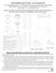
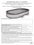
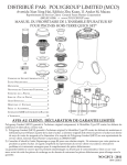
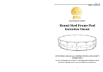
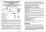
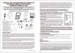
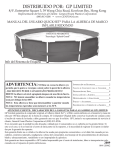
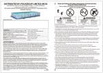
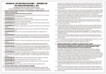
DISTRIBUTED BY: POLYGROUP LIMITED (MCO)
Avenida Xian Xing Hai, Edificio Zhu Kuan, 11 Andar M, Macau
Customer Service Representative: General Foam Plastics Corporation
(800) 813-0206 • www.GENFOAM.com
SFS TYPE SWIMMING POOL FILTER SYSTEM OWNER’S MANUAL
FOR ABOVE GROUND QUICK SET® SWIMMING POOLS
2X
PATENT
PENDING
FILTER
SYSTEM
2X
UL IMPORTANT SAFETY INSTRUCTIONS___2
PRELIMINARY STEPS________________2
POWER FILTER____________________2
FILTER CARTRIDGE CLEANING_________5
POOL MAINTENANCE________________6
POOL WATER CARE________________7
TROUBLE SHOOTING GUIDE___________8
DISASSEMBLY AND STORAGE_________8
PARTS & ACCESSORIES_____________9
NOTES________________________10
12X
2X
F1000C / F1500C / F2000C
F600C & F700C
ATTENTION CUSTOMER: STATEMENT OF LIMITED WARRANTY
Polygroup Limited (MCO) warrants to the original purchaser only, the SFS Type Power Filter against defects in material and workmanship, as follows:
1) Polygroup Limited (MCO) warrants to the original purchaser, the SFS Type Power Filter against defects in material and workmanship for 180-days from the date of purchase. Original Purchaser must retain proof of such
purchase in the form of a store sales receipt and must produce such upon request by Polygroup Limited (MCO)
or its customer service representative, General Foam Plastics Corporation at (800) 813-0206.
2) You should first consult the Trouble Shooting guide for a simple solution, page #8. If still unable to correct the
situation, please contact customer service representative General Foam Plastic’s customer service at
(800) 813-0206. Do not return your pool or parts to the place of purchase. A knowledgeable customer service
representative will assist you in resolving the problem and arrange replacement of defective parts, if needed.
If the unit is found to have been consumer damaged or abused, it is not covered by the limited warranty. If this is
the case, you will be advised of the cost of replacement part(s), or the need to return damaged part(s) for warranty
replacement.
WITH GFCI - 2011
084-120839
2
IMPORTANT SAFETY INSTRUCTIONS
When installing and using this electrical equipment, basic safety precautions should always be followed, including
the following:
READ AND FOLLOW ALL INSTRUCTIONS
1.
2. WARNING - To reduce the risk of injury, do not permit children to use this product unless they are closely
supervised at all times by an adult who is capable of assisting a child in distress.
3. WARNING - Risk of electrical shock. Connect only to a grounding type receptacle. This product is provided
with a ground-fault circuit-interrupter. If replacement of the plug or cord is needed, use only identical replacement parts.
4. WARNING - To reduce the risk of electrical shock, replace damaged cord (with pump body) immediately.
NEVER bury cord. Locate cord to eliminate abuse or contact from lawn mowers, hedge trimmers, and other
equipment. NEVER use an extension cord to connect unit to electric supply; provide a properly located outlet.
5. CAUTION - The power filter is for use with storable pools only. DO NOT use with permanently installed
pools. A storable pool is constructed so that it may be readily disassembled for storage and reassembled to its
original integrity. A permanently installed pool is constructed in or on the ground or in a building so that it cannot be readily disassembled for storage.
6. The unit is provided with a ground-fault circuit-interrupter (GFCI). To test the GFCI, push the test button. The
GFCI should interrupt power. Push the reset button. Power should be restored. If the GFCI fails to operate in this
manner, the GFCI is defective. If the GFCI interrupts power to the pump without the test button being pushed, a
ground current is flowing, indicating the possibility of an electric shock. Do not use this pump. Disconnect the
pump and have the problem corrected by a qualified service representative before using.
7.
SAVE THESE INSTRUCTIONS.
PRELIMINARY STEPS
1. READ ALL INSTRUCTIONS CAREFULLY and get a thorough understanding of what is required to
assemble your Type SFS Power Filter.
2. Before you begin to assemble the pool, identify, count, and check all parts needed for assembly. Refer to the
“PARTS LIST AND ACCESSORIES”, Page #9, under the quantity column for your size pool.
3. It is recommended that you have some PETROLEUM JELLY on hand for lubricating the gaskets
IMPORTANT NOTES:
POWER FILTER
1. Installer shall follow written instructions provided for operation of the circulation systems.
2. All electrical components shall be installed in accordance with Article 680 of the National Electrical Code
(NEC) “Swimming Pools, Fountains and Similar Installations” or its latest approved edition.
3. The Filter Cartridge (9) 3-3/4” will hold as many as 2 of the 1” diameter chlorine tablets and the 8” will hold
as many as 6 of the 1” diameter chlorine tablets. Check your chlorine levels to determine the proper number of
chlorine tablets to add. The filter cartridge will automatically dispense chlorine into the pool as the pump runs.
You must have the type of Filter Cartridge (9) with a central core mesh divider (See page 3) to use the
chlorine dispenser. DO NOT use this to dispense powdered chlorine, shock treatment or any other type of
chemicals as damage to the pump, filter cartridge, and pool will occur.
4. These Skimmer Filter Systems are manufactured by Dongguan Polyfilm Plastics Products Co. Ltd. and UL Listed
(file #E307476) - double insulated and grounded - 115 V.A.C. - 60 Hz. (Unit must have a minimum of 105
V.A.C. to start and run properly.) The units’ wattage and capacity is as follows:
SFS600 Filter System with F600C Pump
46 watts
0.8 amps
580 G.P.H.
2
SFS600 Filter System with F700C Pump
57 watts
1.1 amps
780 G.P.H.
SFS1000 Filter System with F700C Pump
57 watts
1.1 amps
780 G.P.H.
SFS1000 Filter System with F1000C Pump
80 watts
2.2 amps
1075 G.P.H.
SFS1000 Filter System with F1500C Pump
SFS2000 Filter System with F2000C Pump
120 watts
210 watts
2.0 amps
2.2 amps
1500 G.P.H.
2000 G.P.H.
THE FILTER CARTRIDGE (9) WILL HOLD 1”
DIAMETER CHLORINE TABLETS. CHECK
YOUR CHLORINE LEVELS TO DETERMINE
THE PROPER NUMBER OF TABLETS
TO ADD.
11
17
18
10
19
YOU MUST
HAVE THIS
TYPE OF
FILTER WITH
A CENTRAL
CORE MESH
DIVIDER
TO USE THE
CHLORINE
DISPENSER.
12
9
14
US PATENT
# 7,005,062
22
8
23
22
PATENT
PENDING 28
FILTER
SYSTEM
29
7
30
NOTE:
6
13
14
1-6
FIG. 1
12
1-6
1
2
2A
2B
2C
2D
2E
3
4
5
6
32
7
16
8
9
15
10
20
11
12
21
13
14
15
16
17
18
24
30
19
12 EA.
20
25
21
NOTE:
Install Service 22
23
Plugs (30)
24
only
when
26
25
servicing
26
system!
27
27
28
29
30
32
PUMP BODY W/CORD
ROTOR ASSEMBLY
MAGNET AXLE
IMPELLER
SHAFT
THRUST WASHERS
SHAFT END CAPS
PUMP GASKET
VOLUTE HOUSING
PHILLIPS HEAD SCREWS
O-RING
PUMP RETAINING NUT
SKIMMER CANISTER
FILTER CARTRIDGE
STRAINER BASKET
LOCK TOP
O-RING
RETURN HOSE
HOSE CLAMP
POOL WALL FITTING
GASKET
THRUST WASHER
NUT
ELBOW 90°
DIVERTER FITTING
LOCKING RING
GASKET
FACE PLATE
HEX HEAD SCREWS
WEIR FOAM
WEIR
VACUUM ADAPTER
DRAIN CAP
SEAL GASKET
SERVICE PLUGS
POOL WALL
When Pump (1) needs servicing or working on Return
Hose (13), turn off power and install the Service Plug
(30) into Pool Wall Fitting (15) after removing Locking
Ring (21) and Diverter Fitting (20). Also install a Service
Plug (30) into center hole of the Skimmer Canister (8)
after removing the Pump Retaining Nut (7). See FIG. 1.
When service is complete remove both Service Plugs (30)
reversing the procedures above.
IMPORTANT! Your pump is protected by a thermal
overload. This device senses the temperature of the pump
and if it is getting too hot, it will open the electric circuit
and the pump will stop running until it cools off some. It
will automatically turn back on when it has cooled down
enough. This is a safety device to help prevent excessive
pump damage.
If your pump is doing this, it is because of high pool water
temperature and/or high air temperature and/or low water
flow thru the pump. If this happens you need to check
water flow thru the filter and correct it if needed. This
pump uses the water flow for cooling. You may also want
to run the pump at night when the temperature is lower.
2E
3
KEY DESCRIPTION
5
2E
4 EA.
2 EA.
4
2B
3
2A
5
6 EA.
4
3
2 EA.
2B
2
2A
2
2C
2C
2D
2 EA.
F600C & F700C
1
1
2D
2 EA.
F1000C / F1500C / F2000C
Should you encounter any problems, contact the Customer Service Representative/Parts Department at (800) 813-0206
from 8 AM to 5 PM Mon. thru Fri. EST. Extended operating days and hours during peak season requirements.
3
4
1. POWER FILTER INSTALLATION:
(REFERENCE PAGE 3, FIG. 1)
WARNING - EXTREMELY IMPORTANT!
• Risk of electrical shock, connect only to a grounding type receptacle.
• Receptacle must be at least 10 feet away from pool.
• Filter system can be used as many hours as desired, but NEVER when the pool is
occupied.
• Do not use an extension cord to connect unit to electric supply; provide a properly
located outlet.
• Do not bury the cord.
NOTE - The Power Filter will be in four sections: a pump; filter assembly; hardware
bag; and return hose.
A. First, Locate the filter assembly, remove the Lock Top (11), Strainer Basket (10),
and Filter Cartridge (9) from the assembled Filter Case. Locate the mounting loca- FIG. 2
tion for the power filter on the Pool Wall (32). Install one Gasket (22) over the four
alignment pins on the skimmer canister (8) and place it up to the outside pool wall inserting the four alignment pins through
the four large holes in pool wall. Now leaning against the Skimmer to hold it in place add the inside gasket (22) over the
pins on the inside of the pool wall. Now place the Face Plate (23) over the alignment pins. Place the Hex Head Screws (24)
into their holes. Start all the Hex Head Screws one and a half turns each. Then proceed in tightening them in equal turns
each in sequence around the Face Plate until all are equally tight and you have a good even seal. Warning! Be sure not to
over tighten them, you just need a water tight seal.
B. Now lubricate the pump O-ring (6) with petroleum jelly (not provided). Hold the Skimmer Canister (8) securely, and insert
pump assembly (1-6) so that the outlet on the Volute Housing (4) extends out to the side of the canister as shown in Fig. 2.
Insert the pump until it bottoms out, and the two ribs on the volute housing insert
into the two slots on the bottom of the canister. Reach down inside the canister and
32
place the Pump Retaining Nut (7) over the top of the volute housing inlet as shown
in Fig. 2. Twist the Nut (7) clockwise until it is snug.
C. Locate the Pool Wall Fitting assembly parts (15-21). Lubricate the black Wall
Fitting Gasket (16) with petroleum jelly and install it over the threads on the Pool
Wall Fitting (15). Insert the pool wall fitting with the gasket through the hole in
the wall from the inside of the pool. Place the Thrust Washer (17) over the pool
wall fitting and then thread the Wall Fitting Nut (18) onto the fitting until it is hand
tight. DO NOT over tighten the wall fitting nut or wrinkle the pool wall around
the Wall Fitting Thrust Washer (17) or Wall Fitting Gasket (16). Now apply some
petroleum jelly to the thread of the Elbow 90° (19) and install the elbow into the
wall fitting assembly. Install the Diverter Fitting (20) and Locking Ring (21) onto FIG. 3
6
the wall fitting.
D. Get the Return Hose (13) and remove the two Hose Clamps (14) from the hardware bag. Loosen the hose clamps and slide
them over the end of the hose. It is recommended to lubricate the O-Rings (12) on the Volute Housing (4) and on the Elbow
(19) before installing the hose (13). Install the hose on the pump volute housing and on the Elbow (19). Tighten both of the
Hose Clamps (14). See Fig. 3.
E. Place the Filter Cartridge (9) and the Strainer Basket (10) back into the SkimMAX. WATER
mer Canister (8). It is important that the Filter Cartridge (9) slips over the Pump
LEVEL
Retaining Nut (7) and seals at the bottom of the canister so that the Strainer
Basket (10) will seat in it’s groove inside the canister. See Fig. 4. Place the Lock
Top (11) on top of the Skimmer Canister (8) and lock it in place by turning it
MIN. WATER
clockwise until it is locked. Push the Weir Foam Pad (25) into the Weir (26) and
LEVEL
under the tabs, to hold it in place. Take the Weir (26) and slide it into the grooves
from inside the pool. See Fig. 4. Once the weir is pushed inside the grooves, flip it
over as shown by the Arrow #2 in Fig. 4, to lock it in place. NOTE: The weir can
ONLY be pushed into the grooves as shown by Arrows #1 in Fig. 4, by holding
it horizontal. Be sure the weir moves freely through the opening, if not carefully
trim away any obstructing material to allow the weir to move freely.
F. After the pool is filled, SEE (WATER LEVEL FIG. 4) check the hose connections FIG. 4
and fittings to make sure there is no water leakage. If any leaks are found, see #4
in the Trouble Shooting guide on page #8.
4
2. PUMP OPERATION:
5
IMPORTANT: FILTER CARTRIDGE MUST BE FIRMLY SEATED OVER THE PUMP INTAKE PORT
TO FILTER THE POOL WATER EFFICIENTLY.
NOTE: ONLY FILTER CARTRIDGES WITH A 1-3/4” INCH DIAMETER HOLE WILL WORK
PROPERLY. ANY OTHER SIZE HOLE WILL PREVENT PROPER FILTRATION. THE CARTRIDGE
MUST SEAL TIGHTLY AROUND BOTH ENDS.
A. Plug the power cord of the filter assembly into a properly grounded receptacle, located at least 10 feet away from
the pool.
B. Check the return fitting on the inside of the pool for correct flow, it should feel like a solid stream of water
returning to the pool. You can use the return flow as a gauge to determine when the filter needs cleaning and/or
replacement. If you feel a reduction in flow, clean and/or replace filter.
C. Test water and adjust as needed, see “POOL WATER CARE”, page #7. VERY IMPORTANT – PUMP AND
FILTER ALONE WILL NOT PREVENT ALGAE FROM GROWING IN POOL WATER; THIS CAN
ONLY BE DONE BY MAINTAINING PROPER CHLORINE AND pH LEVELS AT ALL TIMES!
D. The filter may need to be cleaned and/or replaced several times at start up until the correct chlorine and pH levels
are attained. We recommend that you keep at least one spare cartridge on hand at all times. Filter cartridges may
be purchased at the store you purchased your pool from, or ordered from GFP, see page #9, Item #9.
E. There is a Drain Cap (#28) and Seal Gasket (#29) at the bottom of the Filter Canister (#8) to allow you to drain
off sediment and debris at the bottom of the canister. Place them back on and hand tighten only after allowing
them to drain off a little water to flush the canister bottom out.
3. FILTER CARTRIDGE CLEANING INSTRUCTIONS:
A. You will need to clean the Filter Cartridge. First, unplug (turn off) the Power Filter. Then remove the Lock Top
(11) by turning it counter clockwise. Remove the Strainer Basket (10) and the Filter Cartridge (9).
B. The filter cartridge can be cleansed of coarse dirt and debris by pressure washing inside and out with a garden
hose, making sure to wash between all pleats. Fine particles of dirt are more easily removed from the filter
pleats when the cartridge is dry. Therefore, after hosing the cartridge, allow the filter to dry and CAREFULLY
BRUSH, but do not scrub the pleated surface areas. Cleaning and scrubbing a filter too vigorously will also
wear out the cartridge much faster than if it is simply hosed off correctly.
C. Suntan oils, body oils, and algae can form a coating on the filter pleats which may not be thoroughly removed
by hosing. Such films of oils and/or algae will rapidly clog up the filters’ pores, greatly reducing filtration.
Therefore, it is imperative to remove such materials from the filter element as soon as possible. To remove oils,
we recommend soaking the cartridge in a solution of 1 pound of trisodium phosphate (or any other strong
detergent) to 5 gallons of water for up to 12 hours. Trisodium phosphate is available in many supermarkets,
hardware stores, or janitorial supply stores. After the oils have been removed, rinse the filter cartridge to remove
any dirt. If algae is a problem, add 1/2 pint of pool chlorine or 1 pint of liquid household bleach to the cleaning solution, 1 hour before removing the filter cartridge from the solution. Thoroughly rinse the filter cartridge
before replacing it in the filter case. Check the pool chemistry to determine the cause of algae growth.
D. Excessive calcium and/or mineral deposits may build up on a filter cartridge and should be handled differently.
Contact your local pool supply store to ask about additional filter cartridge cleaners or treatment for calcium or
mineral deposits. Check pool chemistry for high pH or alkalinity; this may cause a calcium or mineral build-up.
Now is a good time to put chlorine tablets into the Filter (9) if necessary..
E. A spare “stand-by” Filter Cartridge is an excellent investment. It provides a convenient way to continue filtration of your pool while cleaning or replacing a dirty Filter Cartridge. Also, a well-maintained, clean cartridge
assures you that your filter will always be ready to operate at peak efficiency.
Should you encounter any problems, contact the Customer Service Representative/Parts Department at (800) 813-0206
from 8 AM to 5 PM Mon. thru Fri. EST. Extended operating days and hours during peak season requirements.
5
6
POOL MAINTENANCE
USING THE DIVERTER FITTING AND VACUUM ADAPTER
1. DIVERTER FITTING USE; diverts direction of return water entering the pool, see part #20 FIG.5. You
can adjust the fitting by loosening the LOCKING RING see part # 21 FIG 5. The DIVERTER FITTING can be
used to help generate clockwise rotation of the pools water toward the SKIMMER intake opening area of your
pools wall. To do so slightly loosen the LOCKING RING and rotate the DIVERTER FITTING upward pushing
water horizontally under the waters surface pointing away from the SKIMMER Intake area. DO NOT POINT it
directly toward the SKIMMER this will deeply decrease skimming and filtration. Tighten the LOCKING RING
to hold the DIVERTER FITTING in the desired position you choose. You can
position the DIVERTER FITTING downward later to assist in keeping sediment from building along the bottom of your pool.
2. VACUUM ADAPTER USE; allows you to vacuum your pool, see part # 27
FIG.4 The VACUUM ADAPTER is included with the SKIMMER unit, it will
be necessary for you to purchase a Vacuum, Vacuum handle, and a Vacuum
hose from your local pool supply retailer, also your home improvement centers, and large retail stores sometime carry these as seasonal items and they
range from economy to deluxe.
3. To install the VACUUM ADAPTER turn off your pump, remove the WEIR part
# 26 FIG. 4, see the section on WEIR installation page 4 (step E) and reverse
the process by lowering the WEIR and sliding it out through the openings in FIG. 5
the FACE PLATE part # 23 shown in FIG 4. Place the WEIR in a safe place
because you need to reinstall it after vacuuming so that your skimmer operates properly.
4. Next attach your vacuum to it’s handle and place the swivel end of
the hose on the vacuum unit and lower vacuum into the pool. Place
your vacuum hose into the pool (it will float somewhat), keep the
remaining end near the DIVERTER FITTING, now turn on the
pump and hold the hose up to the DIVERTER FITTING filling the
hose, this primes the hose with water pushing out the air. The hose
will sink as it fills. Now that the hose is filled, turn off the pump
again and slide the VACUUM ADAPTER into the SKIMMER
opening and attach hose to the adapter. Now start your pump, keeping the vacuum under water at all times during this process. Now
you can move your vacuum along the bottom cleaning your pool.
Never Use the hose alone without the vacuum attached, liner
damage could occur, also Never vacuum with the Strainer Basket removed or Filter out, pump blockage and damage will occur. Never leave hose hanging out of the pool because a siphon
can occur draining your pool.
5. When you finish vacuuming turn off the pump once more. Slide
FIG. 4
the VACUUM ADAPTER out of the SKIMMER and reinstall the
WEIR back into place. Remove the hose and vacuum draining the
hose back into the pool as you raise it out of the water. Remove the
STRAINER BASKET, empty and rinse it, also remove your FILTER CARTRIDGE and clean it according to
instructions page 5 step 3. Now place the FILTER CARTRIDGE back in and add your chlorine tablets, install the
STRAINER BASKET and the LOCK TOP.
NOTE: It’s a good practice to store the Vacuum Adapter, Vacuum Unit, Vacuum Hose, and Handle in a good location to prevent damage or loss and possible UV weathering which might result in early failure.
USING THE SERVICE PLUGS: When Pump (1) needs servicing or working on Return Hose (13), turn off
power and install the Service Plug (30) into Pool Wall Fitting (15) after removing Locking Ring (21) and Diverter Fitting (20). Also install a Service Plug (30) into center hole of the Skimmer Canister (8) after removing the
Pump Retaining Nut (7). See Fig. 1 page 3 for location of each. When service is complete remove both Service
Plugs (30) by reversing the procedures above.
6
1.
2.
3.
4.
POOL MAINTENANCE:
7
Check and adjust pH and chlorine levels daily using required chemicals. See “POOL WATER CARE”, below.
Check filter output daily. If flow is reduced, see Symptom 2 in “TROUBLE SHOOTING GUIDE”, page #8.
Check filter for leaks. If a leak is found, see Symptom 4 in “TROUBLE SHOOTING GUIDE”, page 8.
Check seams in pool periodically. Minor repairs may be made with the patch kit (supplied with pool). Additional
patches are available from General Foam Plastics or your local pool supply store.
POOL WATER CARE
1. The following items are required and readily available from your local pool supply store:
A. TEST KIT - Used to check chlorine and pH levels.
B. 1” CHLORINE TABLETS - Used to disinfect pool water and help control the growth of algae.
C. pH CONTROL CHEMICALS - Used to adjust pH levels Up (Soda Ash) or Down (Acid).
D. ALGAECIDES - Used to eliminate algae.
E. SUPERCHLORINATOR - Used to destroy combined chlorine, ammonia, nitrogen, and organic compounds.
F. LEAF NET with handle - Used to remove leaves, trash, insects, etc. from pool.
G. CHLORINE DISPENSER (Supplied with Filter) - Used to dispense 1” chlorine tablets ONLY.
2. Use test kit daily to check pH and chlorine levels. Adjust accordingly using the required chemicals.
NOTE: Excessive levels of chlorine or low pH levels will damage pool liner.
3. The pool can be cleaned using a garden hose powered vacuum from General Foam Plastics or a pool supply store.
4. Using a foot bath near the pool to wash off your feet prior to entering the pool will assist in keeping the pool clean.
5. Well water often presents special problems with water chemistry. If you must use well water, take a sample to
your local pool chemical supplier for analysis before adding ANY chemicals.
6. Use the gallons for your pool to calculate the amount of chemicals you will need to correct the pool water based on
the gallons of water in your pool. Note: It is recommended to use a 5 gallon bucket of water to mix and dissolve
your chemicals and then applying directly to the pool water. Follow manufacturers label directions on all chemicals.
For your convenience, fill in your pool’s information in the below chart. This info is in your pool set-up instruction manual.
POOL TYPE
FILTER/PUMP TYPE
POOL CAPACITY/GALLONS
*Most pool supply stores will test your pool water for free and advise you of what chemicals you need, and the
correct amount to use for your pool. You will need to tell them the pool capacity in gallons.
7. IMPORTANT - We cannot over-stress the importance of proper and adequate daily chemical treatment. Chlorine and pH levels must be maintained at all times. PUMP AND FILTER ALONE WILL NOT PREVENT
ALGAE FROM GROWING IN POOL WATER; THIS CAN ONLY BE DONE BY MAINTAINING
PROPER CHLORINE AND pH LEVELS AT ALL TIMES.
A. Maintain pH level between 7.3 and 7.8.
B. Maintain chlorine level between 1.0 and 1.6 ppm (parts per million).
C. Superchlorinate your pool at least every other week.
NOTE:
1. Hot weather/heavy use may require pH and chlorine levels to be maintained on the upper side of the scale and
superchlorination of the pool every week.
2. Using a pool cover and/or solar cover will assist in maintaining your pH and chlorine levels by reducing the
amount of evaporation from your pool.
CAUTION - Concentrated chlorine levels and low pH levels will damage pool.
DANGER - You must follow the instructions for the pool chemicals you use, as to quantity and recom-
mended usage.
NEVER drop lumps or pellets of chemicals in pool; this may present a hazard to swimmers and/or damage your liner.
7
8
TROUBLE SHOOTING GUIDE
DISCONNECT ELECTRICAL CORD BEFORE TROUBLESHOOTING FILTER
SYMPTOM
PROBLEM
1 Motor fails to start or
A Unit Not Plugged In
A Unit must be plugged into a 3-wire grounded outlet.
B GFCI Breaker Tripped
B Reset circuit breaker. If problem persists, have an electrician check circuit.
C Low Voltage
C Check line voltage - must be 105 to 125 AC volts.
D Rotor Jammed
D See the “Rotor Service” diagram in the assembly view of the Filter/Pump unit, page #3.
A Low Water Level
A Water level must be within 1” above or below the center line of the Power Filter Inlet
kicks on and off.
2 No flow or low flow
through return hose
POSSIBLE SOLUTION
opening.
B Inlet / Discharge Clogged
B Check for obstructions at strainer basket and in return hose.
C Filter Dirty
C Clean (see page #5) or replace cartridge. Spare cartridges make service more convenient.
D Rotor Jammed
D See the “Rotor Service” diagram in the assembly view of the Filter/Pump unit, page #3.
3 Filter is not cleaning pool A Chlorine Level
(water cloudy, green, etc.) B Filter Dirty
A Maintain chlorine level between 1.0 and 1.6 ppm
B Clean (see page #5) or replace cartridge. Spare cartridges make service more convenient.
C pH Level
C Maintain pH Level between 7.3 and 7.8.
D Cartridge Damaged
D Check cartridge for damage and/or holes. Replace if damaged.
E Low Water Flow
E Check for obstructions at strainer basket and in return hose.
F Other Chemicals Required F Have water tested at pool supply store. It may be necessary to add other chemicals
due to varying water quality in different localities.
4 Water Leakage
G Pool Water Very Dirty
G Run pump more often, but never when pool is in use. Clean filter more often.
A Return Hose
A Adjust hose clamps (14) on cuff, check O-Ring (12) and retighten. Check hose for any
(2) connection points
holes or cracks. Replace if needed. See page #3.
B Pump to Volute Housing
B Tighten screws (5). Check Pump Gasket (3) for damage. Replace if needed. See page #3.
C Volute Housing to Filter
C Check Volute Housing O-Ring (6) for damage. Replace if needed. See page #3.
PROBLEMS: Call GFP Corp. Parts Dept. at 1-800-813-0206 between 8 AM and 5 PM Mon. - Fri. EST.
Extended operating days and hours during peak season requirements.
POWER FILTER DISASSEMBLY AND STORAGE
A. First, unplug the main power cord of the Power Filter.
B. Remove the Lock Top Retainer (11) by turning counter-clockwise to unscrew. Remove Strainer Basket (10)
and the Filter Cartridge (9) and remove any chlorine tablets left inside the core section of the filter.
C. Loosen all the Hose Clamps (14), remove the Return Hose (13) and allow water to drain out.
D. Remove the Pool Wall Fitting (15-21) clean the parts and lubricate Gasket (16) with petroleum jelly and
reassemble all parts then place them in a safe place.
E. Remove the Pump Retaining Nut (7) by turning it counter-clockwise and then remove the Pump lowering it
from the Skimmer Canister (8) now clean the pump, dry it off, and then lubricate both the O-Rings (6, 12) on
the pump with petroleum jelly and place it in a safe place.
F. Remove the Hex Head Screws (24) from the Skimmer Face Plate (23) being sure to support the Skimmer
Canister (8) from falling and carefully remove the Face Plate (23), the Weir (26) and the Gasket (22). Next
remove the Skimmer Canister (8) and the remaining Gasket (22). Clean all parts, dry them off, and reassemble partially tightening the Hex Head Screws (24). Clean and reassemble the Strainer Basket (10) and the
Lock Top (11) onto the Filter Case (8). Place the assembled unit in a safe place.
G. Clean and dry all filter cartridges, place them with the Skimmer Canister unit, Pump, Return Hose, Clamps
and the Wall Fitting in a safeplace.
8
Should you encounter any problems, contact the Customer Service Representative/Parts Department at (800) 813-0206
from 8 AM to 5 PM Mon. thru Fri. EST. Extended operating days and hours during peak season requirements.
KEY
1
2
3
4
5
6
*
7
8
9
*
10
11
12
13
14
15
16
17
18
19
20
21
22
23
24
25
26
27
28
29
30
31
32
*
9
DESCRIPTION
FILTER
PUMP BODY WITH CORD & GFCI
ROTOR ASSEMBLY
PUMP GASKET
VOLUTE HOUSING
PHILLIPS HEAD SCREW (6 PC)
O-RING - (On Volute Housing)
ASSEMBLED PUMP #1 THRU #6
PUMP RETAINING NUT
SKIMMER CANISTER
3-3/4” FILTER CARTRIDGE 2 SQ. FT
8” FILTER CARTRIDGE 7 SQ. FT
STRAINER BASKET
LOCK TOP
O-RING - (Hose Connection)
RETURN HOSE 3 FT.
HOSE CLAMP
POOL WALL FITTING
GASKET
THRUST WASHER
NUT
ELBOW 90°
DIVERTER FITTING
LOCKING RING
GASKET
FACE PLATE
HEX HEAD SCREWS (12 EA.)
WEIR FOAM
WEIR
VACUUM ADAPTER
DRAIN CAP
SEAL GASKET
SERVICE PLUG
INSTRUCTION MANUAL
PATCH KIT
ASSEMBLED FILTER #1 THRU #30
SFS1000/F1000C
SFS1000/F700C
SFS FILTER SYSTEM PARTS LIST
SFS1000/F1500C
45.00
20.00
2.50
5.00
.75
1.50
75.00
1.50
6.00
-10.00
3.00
5.00
2.00
3.50
.25 ea
3.00
1.50
1.25
1.75
5.00
2.00
3.00
2.00
5.00
1.25
2.50
3.00
5.00
.75
.25
2.00
2.00
2.00
95.00
096-050604
096-050505
078-110078
078-110097
090-010063
090-130012
096-050609
078-110110
078-110219
-090-130011
078-110222
078-110221
090-130030
063-060010
090-160005
078-110223
078-110224
078-110225
090-020047
078-110226
078-110227
078-110228
078-110229
078-110230
090-010063
090-330027
078-110231
078-110251
078-110254
078-110255
078-110126
084-120839
090-250002
096-050620
35.00
15.00
2.50
3.00
.75
1.25
50.00
1.50
6.00
-10.00
3.00
5.00
2.00
3.50
.25 ea
3.00
1.50
1.25
1.75
5.00
2.00
3.00
2.00
5.00
1.25
2.50
3.00
5.00
.75
.25
2.00
2.00
2.00
90.00
096-050605
096-110003
078-110031
078-110189
090-010063
090-130012
096-050610
078-110110
078-110219
-090-130011
078-110222
078-110221
090-130030
063-060010
090-160005
078-110223
078-110224
078-110225
090-020047
078-110226
078-110227
078-110228
078-110229
078-110230
090-010063
090-330027
078-110231
078-110251
078-110254
078-110255
078-110126
084-120839
090-250002
096-050621
30.00
10.00
1.50
3.00
.75
1.25
45.00
1.50
6.00
-10.00
3.00
5.00
2.00
3.50
.25 ea
3.00
1.50
1.25
1.75
5.00
2.00
3.00
2.00
5.00
1.25
2.50
3.00
5.00
.75
.25
2.00
2.00
2.00
80.00
SFS600/F700C
096-050605
096-110003
078-110031
078-110189
090-010063
090-130012
096-050610
078-110110
078-110249
090-050140
-078-110222
078-110221
090-130030
063-060010
090-160005
078-110223
078-110224
078-110225
090-020047
078-110226
078-110227
078-110228
078-110229
078-110230
090-010063
090-330027
078-110231
078-110251
078-110254
078-110255
078-110126
084-120839
090-250002
096-050622
30.00
10.00
1.50
3.00
.75
1.25
45.00
1.50
4.50
5.00
-3.00
5.00
2.00
3.50
.25 ea
3.00
1.50
1.25
1.75
5.00
2.00
3.00
2.00
5.00
1.25
2.50
3.00
5.00
.75
.25
2.00
2.00
2.00
70.00
SFS600/F600C
096-050606
096-050137
078-110186
078-110187
090-010063
090-130012
096-050611
078-110110
078-110249
090-050140
-078-110222
078-110221
090-130029
063-060032
090-160009
078-110223
078-110224
078-110225
090-020047
078-110250
078-110227
078-110228
078-110229
078-110230
090-010063
090-330027
078-110231
078-110251
078-110254
078-110255
078-110126
084-120839
090-250002
096-050623
20.00
8.00
1.00
1.50
.75
1.25
30.00
1.50
4.50
5.00
-3.00
5.00
2.00
3.50
.25ea
3.00
1.50
1.25
1.75
4.00
2.00
3.00
2.00
5.00
1.25
2.50
3.00
5.00
.75
.25
2.00
2.00
2.00
70.00
COST ID NUMBER COST ID NUMBER COST ID NUMBER COST ID NUMBER COST ID NUMBER COST
SFS2000/F2000C
ID NUMBER
096-050603 45.00 096-050604
096-050565 25.00 096-050598
078-110078
2.50 078-110078
078-110147
5.00 078-110197
090-010063
.75 090-010063
090-130025
1.50 090-130012
096-050607 75.00 096-050608
078-110143
1.50 078-110110
078-110218
6.00 078-110219
---090-130011 10.00 090-130011
078-110220
3.00 078-110222
078-110221
5.00 078-110221
090-130030
2.00 090-130030
063-060010
3.50 063-060010
090-160005 .25 ea 090-160005
078-110223
3.00 078-110223
078-110224
1.50 078-110224
078-110225
1.25 078-110225
090-020047
1.75 090-020047
078-110226
5.00 078-110226
078-110227
2.00 078-110227
078-110228
3.00 078-110228
078-110229
2.00 078-110229
078-110230
5.00 078-110230
090-010063
1.25 090-010063
090-330027
2.50 090-330027
078-110231
3.00 078-110231
078-110251
5.00 078-110251
078-110254
.75 078-110254
078-110255
.25 078-110255
078-110126
2.00 078-110126
084-120839
2.00 084-120839
090-250002
2.00 090-250002
096-050618 125.00 096-050619
1
1
1
1
1
1
1
1
1
1
1
1
1
2
1
2
1
1
1
1
1
1
1
1
1
1
1
1
1
1
1
2
1
1
1
QTY
4
1/2
1/4
1/4
1/4
1/4
5
1/4
2
1
1
1/4
1
1/4
1
1/2
1/2
1/4
1/4
1/4
1/2
1/2
1/2
1/4
1/4
1/4
1/4
1/4
1
1/4
1/4
1/2
1/2
1/4
8
SHIPPING
WEIGHT
9
10
10
NOTES
Should you encounter any problems, contact the Customer Service Representative/Parts Department at (800) 813-0206
from 8 AM to 5 PM Mon. thru Fri. EST. Extended operating days and hours during peak season requirements.