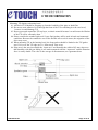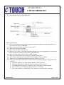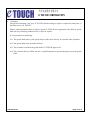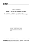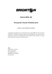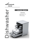
1
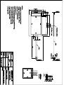
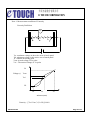
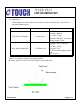
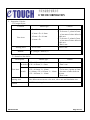
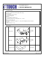
Bolymin, Inc. ◆◆◆ TOUCH PANEL SPECIFICATION MODEL NO. TP240128A TOUCH PANEL FOR BG240128A FOR MESSRS: ________________________________________________ ON DATE OF: ________________________________________________ APPROVED BY: ________________________________________________ 介面光電股份有限公司 E TOU CH C OR PO RA TIO N 1. Product Type: Resistance Type Analog Type 4-Wires Type Film on Glass 2. Criteria of Materials: (a) Upper Electrode: Type: Anti- Glare /Anti-Newton’s Ring Base material: ITO Film Thickness: 188 ±10 um Resistance : 500 ±100 Ω/sq (b) Lower Electrode: Base Material: ITO Glass Thickness: 1.10 ±0.1 mm Resistance: 500 ±100 Ω/sq (c) Criteria of FPC: Base Material: Polyimide Film Tail thickness: 0.30 ±0.05 mm Conduct layer: Copper Insulation layer: Coverlet 3. Definition: 3.1 Active area: Area to be guaranteed all characteristics stated on this specification. 3.2 View area: View area, which is inside adhesive zone or electrode pattern. 3.3 Non-active area: Area to protect miss- input when top enclosure edge touches the touch panel. 055703314102 Page 3 of 15 介面光電股份有限公司 E TOU CH C OR PO RA TIO N 4. Characteristics: 4.1 Mechanical: Description Specification Outside Dimension 87.00 mm x 142.00 mm View Area 68.60 mm x 123.60 mm Active Area 64.60 mm x 120.60 mm Product Thickness 1.40 ±0.20 mm Input method Finger or Pen Activation force Hardness of surface 20g ~ 100g 3H Remark Test Condition: End shape: R0.8mm Resistance between X and Y axis must be equal or lower than 2KΩ, the test voltage=DC5V. JIS K 5400 Peeling downward by 90° FPC Peeling Force Min150 g/cm 90° F FPC Bending Resistance 055703314102 Meet electrical spec. after testing Bending degree: 180° Bending radius: R1.0 mm Bending times: 10 times Page 4 of 15 介面光電股份有限公司 E TOU CH C OR PO RA TIO N 4.2 Electrical: Description Specification Operating Voltage DC 5V Operating Current 20 mA Max Remark DC 7V Max. X- axis 420 Ω ~ 1070 Ω At connector Y- axis 140 Ω ~ 460 Ω At connector Circuit Resistance Insulation Resistance ≧ 20MΩ At DC 25 V, ≧ 60 sec. Test Condition Chatting ≦ 10 ms Voltage: 3V and 6V Frequency: 5Hz and 10Hz Material of Pen : Poly-acetal resin End shape: R0.8mm Linearity ≦ ±1.5 % Test Point : 100 Points Test Force : 100 gf Refer to Note 1 055703314102 Page 5 of 15 介面光電股份有限公司 E TOU CH C OR PO RA TIO N Note 1: Measurement condition of Linearity Linearity Definition M a b x Va : maximum voltage in the active area of touch panel Vb: minimum voltage in the active area of touch panel X : random measuring point Vxm: Actual voltage of Lx point Vxi : Theoretical voltage of Lx point Va Voltage (v) Vxm Vxi Vb Lb Lx La Distance(mm) Linearity : [Vxi-Vxm/ (Va-Vb)]*100% 055703314102 Page 6 of 15 介面光電股份有限公司 E TOU CH C OR PO RA TIO N 4.3. Optical: Description Specification Remark Transmittance > 80 % ASTM D1003 Wavelength =550nm Specification Remark 4.4 Processing Environment: Description Operating Temperature -5 °C ~ +60 °C Storage Temperature -20 °C ~ +70 °C Operating Humidity 20% ~ 90% RH Storage Humidity 10% ~ 90% RH 4.5 Environmental test : Under defined terms and condition test, product must be still satisfactory to electrical and mechanical characteristics. ITEM Test Condition Remark High temp./High Humidity test 60 °C @ 90%RH / 240hrs Refer to Note 2 Low temperature -20°C / 240hrs Refer to Note 2 High Temperature 70°C / 240hrs Refer to Note 2 -40°C / 0.5 hrs → 80°C / 0.5 hrs Thermal shock test Total 10 cycles Refer to Note 2 Note2. : To place in room temperature 24 hrs then test. 055703314102 Page 7 of 15 介面光電股份有限公司 E TOU CH C OR PO RA TIO N 4.6 Durability test: Under defined terms and condition test, product must be still satisfactory to electrical and mechanical characteristics. Description Pen Writing Durability Finger knocking Durability Specification Remark ≧ 60,000 times Test Condition: End shape: R0.8mm Load force: 250 gf Writing speed: 300 mm/sec. Material of Pen: Poly- acetal resin Writing length: 35 mm ≧ 1 Million times End shape: R8mm, Hardness 50~60° Load force: 250 gf Frequency: 5 Hz By Silicon rubber tapping at same points Refer to Note 3 Note3: Test condition of Finger knocking Durability: Resistance between X and Y axis must be equal or lower than 2KΩ 055703314102 Page 8 of 15 介面光電股份有限公司 E TOU CH C OR PO RA TIO N 5. Inspection Criteria: 5.1 Foreign Object Location Defect type a. D > 0.3mm b. 0.3mm ≥ D > 0.2mm c. 0.2mm ≥ D > 0.1mm View Area d. 0.1mm ≥ D a. D ≤ 0.5mm Printing Area Remark Criteria a. None b. To be max. 3 points in 5mm ψ,but none of other defect in this area. c. To be max. 5 points in 5mm ψ,but none of other defect in this area. d. Don’t care a. Don’t care D= (Longψ+ Shortψ)/2 5. 2 Scratch or line defect Description Defect type a. W > 0.05mm, L > 3mm line defect b. W ≤ 0.05mm, L ≤ 3mm View Area Scratch Printing Area Remark 055703314102 Criteria a. None b. Don’t care a. None a. W ≥ 0.10mm, L ≥ 10mm b. To be max. 4 points in 5mm b. 0.10mm > W ≥ 0.05mm, L < 10mm ψ,but none of other defect in c. W < 0.05mm, L < 10mm this area. c. Don’t care Line defect can not across view area, silver area and insulation area. W: Width ,L: Length Page 9 of 15 介面光電股份有限公司 E TOU CH C OR PO RA TIO N 5. 3 Newton’s ring a. Inspection condition: Ⅰ.Tools→30W/Normal white light (office lamp) b. Environments: Ⅰ.Illuminance:1000~1500 lx Ⅱ.black background c. Method: Ⅰ.Avoid light to irradiate eyes. Ⅱ.Distance between eyes and panel is 30 ±10cm. Ⅲ.Check ITO film side. Ⅳ.Begin to inspection at angle 60°, then turn left/right/up /down to inspect. d. Criteria: None of Newton’s ring 5.4 Glass flaw T Y X<=3.0mm Y<=3.0mm Z<=T Corner flaw X Z X X<=3.0mm Y<=3.0mm Z<=T Edge flaw Y T Progressive flaw 055703314102 Z None allowed Page 10 of 15 介面光電股份有限公司 E TOU CH C OR PO RA TIO N 6. Serial A B C D E Number: A B C D E 1 2 005 002 001 year month Production Order No. lot order product serial No. 7. Part number: A B 1515 083 A product size B variation code C 1- Analog 2-Digital example: 1→ 2002, 5→2006 example: 2→ February, A→October example: 005→ The Fifth production in February example: 002→ Second Lot of Fifth Production Order. example: 001→ First piece. example: C D E F 1 4 1 04 1515→ 15.15” D 4 is for 4-wire product 8 is for 8-wire product E 1-Film to Glass 2-Film to Film 3-Film to Film to PC 4- Film to Film to Glass F material code 055703314102 Page 11 of 15 介面光電股份有限公司 E TOU CH C OR PO RA TIO N 8. Mounting T/P display to housing bezel 8.1 All kind of T/P should be propping up form the backside of the glass or hard film. 8.2 Do not use twin adhesive to fix through the front of the T/P or and hang it to the case bezel, because it would damage T/P. 8.3 Do not press and expand the T/P top layer, as elastic material because it would cause the lifetime of the T/P will be extremely short. 8.4 Please consider the weather-tight seal if your final product will be used in harsh environmental conditions. Because the conductive area of the flexible tail to sock in water, the migration of the silver may occur. 8.5 When mounting T/P to the housing bezel, the foam gasket should be limited to the T/P gasket area. If it is over the T/P edge area. A “false touch” may occur. 8.6 Edge area is the area just outside the “input area” and normally the width of 0.5 mm, edge area that durability with the pen sliding is one-tenth compared with the “input area” and the actuation force is nearly double. The value is the average of measurement, not a guaranteed one. 055703314102 Page 12 of 15 介面光電股份有限公司 E TOU CH C OR PO RA TIO N 8.7 Recommend design- mounting method: 9. Safety and Attention: 9.1 Since Touch panels consist of glass, please be careful to handle your hand and other part. You must wear gloves at handling. 9.2 Don’t put a heavy shock or stress on Touch panel 9.3 Don’t lift Touch panel by cable. 9.4 Don’t add any stress only film face. 9.5 Please use dry cloth or soft cloth with neutral deterge nt or one with ethanol to clean surface. Forbid wiping the boundary between ITO glass and film. 9.6 Don’t use any organic solvent acid or alkali solution. 9.7 Don’t pile Touch panel. Don’t put heavy goods on Touch panel. 9.8 Don’t bend a cable of Touc h panel for prevent happen to line cut failure. 9.9 Please don’t use following method for insert the cable to connector. 9.10 Please pay attention for the matter as stated below at mounting design of Touch panel and enclosure. Ø Enclosure support to fix Touc h panel must be out of View area. Ø Enclosure edge must be between view area Guaranteed active area Ø We recommend the material of support to fix Touch panel is elastic material Ø Don’t bond top of surface(film) of Touch panel w/ enclosure. Ø The corner parts have conductivity. Don’t touch any metal part after mounting. 055703314102 Page 13 of 15 介面光電股份有限公司 E TOU CH C OR PO RA TIO N 10. Guarantee: The period of warranty, One year, E TOUCH will take charge to repair or replace the fault parts, if the fault cause by E TOUCH. What is called guarantee object is delivery goods. E TOUCH don’t guarantee if the delivery goods fault cause by customer production line’s repair or replace It’s not guarantee as following: 10.1 The goods fault cause by the goods drop or strike after delivery or customer miss-operation. 10.2 The goods fault cause by nature disaster 10.3 The customer reworked the goods before E TOUCH approved it. 10.4 The customer doesn’t follow the user’s manual attention to operate the goods cause the goods fault. 055703314102 Page 14 of 15 介面光電股份有限公司 E TOU CH C OR PO RA TIO N 11. Modify Resume: Version 1.0 055703314102 Description Reference Date 2002/09/19 Page 15 of 15