1
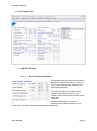
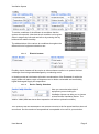
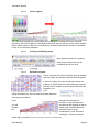
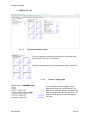
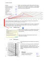
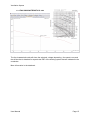
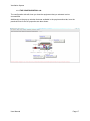
Ventilation Xpress
Ventilation Xpress V6.0.0
User Manual
User Manual
Page 1
Ventilation Xpress
After accepting the disclaimer you come to the :
1. The Welcome Screen
After downloading and running the software on your computer the first time, the above
welcoming window will appear.
We offer you the possibility to check our server if no updated version of the software exists.
This auto-update functionality will only work providing you did not change the file name of
the program.
Possibly you want to deselect this possibility. (Not recommended)
If an update is available you can select the file and download it.
Caution If you are working with translated version of the software only download your
language version! Downloading a different version will replace the earlier selected
language version.
After downloading the update will be installed and the new version of the program will start.
New updates may become available at any time. An update may support new functionalities
or may use new product information to optimise your selection.
It is very likely that the software will use information that is not yet available in a printed
version.
User Manual
Page 2
Ventilation Xpress
The Main Screen
1.1. The menu bar
The title bar will indicate the name of this program with its Version and also the Central Data
Base for our products.
The following usual menu commands are available: NEW, OPEN, SAVE, EXIT
Further, REPORT will allow you to save your selection in a document with an rtf-extension
(Rich Text Formatting) Usually, this kind of file is quite
large ( typically 463KB). For e-mailing purposes possibly you
want to get a more condensed file size. Please save as
“.doc”-file. (typically 151KB) (Using .docx will jeopardise the
numbering formats (MS-Word bug)
DISTRIBUTOR enables you to add your company
details and a bitmap of your company logo that will be
included in the report
User Manual
Page 3
Ventilation Xpress
PREFERENCES will enable you to set the units that you usually work with. In the diagrams
tab you can possibly select another view to see the properties of the moist air (see further)
ABOUT shows the credentials, the disclaimer that you accepted when you opened the
program and also the upgrade button that allows you to check the availability of a more
recent version of the program and give you the possibility to download and installing it. Again,
make sure to select the proper language version
User Manual
Page 4
Ventilation Xpress
1.2. The Program Tabs
1.2.1. SELECTION -tab
1.2.1.1.
Room Airflow Conditions:
We possibly define the required air flow by
setting the required amount per person in
m³/h. (if this unit has been chosen in the
preferences window).
The room surface can be entered and
together with area per person or the
number of persons the total amount will be
computed.
Another possibility is to enter the
previously calculated amounts in m³/h
directly and this both for the supplied and the extracted air.
1.2.1.2.
User Manual
Operation modes
Page 5
Ventilation Xpress
To set the conditions of the different air conditions that the
system will cope with. Note that the air condition can be given
either in degree dry bulb and wet bulb or by entering the dry
bulb and the relative humidity.
The abbreviations of the various air conditions throughout the
different kind of equipment selections are:
1.2.1.3.
Electric heaters
Possibly electric heaters will be require to either enhance comfort or to protect the heat
exchanger from being soaked/damaged by condensing moist.
In Heating mode an inlet heater will avoid a condensation of the Extracted Air whilst the
supply heater will add a couple of degrees more to obtain a selectable and comfortably
higher discharged Supply Air temperature.
1.2.1.4.
Device Family Selection
Here you can select what kind of
equipment you are looking for:
Ventilation Xpress can help you to choose
a Heat Reclaim Ventilation device. The
VAM or VKM (VKM has also a direct expansion coil and an optional humidifier)
Further, a 100% fresh air device , the FXMQ-MF
Your selection will also be based on the comfort level due to the fan speed and thus also unit
sound level. Set the maximum fan speed that is acceptable to be used in your selection.
User Manual
Page 6
Ventilation Xpress
1.2.1.5.
The External Static Pressure
The amount of air that will flow through
your selected device is depending upon the
resistance that is caused by your ducting.
Knowing the required quantities of air for a
room/area, the grilles/louvers that will be used, the ducting components and the acceptable
air velocities obtained because of the ducting dimensions, the total resistance can be
calculated (the VRV Pro selection program will do that for you)
It is very likely that the supply and discharge ESP will be different, resulting into different air
volumes that can pressurise a room or put a room in a depression. In Heat Reclaim
Ventilation this will also affect the efficiency of the equipment and thereto correction factors
will be taken into account.
The values that are entered here are assumed to be the minimum duct resitance. The
program will search for a sollutions that will be able to overcome this resitance. Sollutions
that would have lower ducting resistance are neglected, not considered.
1.2.1.6.
The Altitude above Sea level
A very nice tool to see the importance of
the altitude is the Daikin Psychrometric
Diagram Viewer. There, using the slider
you can see the impact of the altitude to the properties of the air that we use in an Air
Conditioning system.
1.2.1.7.
The Selected Devices
Here you can see that “accepting selections with fresh-up operation” results in far more
candidate solutions.
NOTE: make sure that you use the tab-key to leave an entry field or to click in another
field to accept you changes.
User Manual
Page 7
Ventilation Xpress
1.2.2. PSYCHROMETRICS -tab
Please note that, if you adjusted the preferences to see the Mollier diagram, you will see the
following image:
We will continue to use the next
Psychrometric chart in this manual for
Ventilation Xpress.
Clicking the button “Configuration screen”
allows us to pop-up a window that allows
us to better understand the used
abbreviations in the diagram
User Manual
Page 8
Ventilation Xpress
1.2.2.1.
Colour legend
You can easily change the used colours in the diagram by clicking one of the coloured
squares in the colour legend. A COLOUR-window will open an there you can select another,
better visible colour for the item / lines that you selected. Note that this function is available
in any of our selection programs.
1.2.2.2.
Cooling and Heating mode
Note that the behaviour in heating
mode and cooling mode can be
visualised by just one click.
1.2.2.3.
Dynamic program
The air volumes will cross in the fibre heat exchanger
and both latent and sensible heat will be exchanged.
In case of cooling, the room air (RA) becomes the
exhaust air (EA) and the flow will exchange capacity
with the flow of outdoor air (OA) that will become the
ventilation out
(VO)
Using the sliders you can see how the system behaves
with varying conditions.
If you
you will
be kept
the
decrease the ambient air
condition in the heating mode,
remark that the exhaust air has to
safely away (max95%RH) from
saturation line to avoid
condensation in the fibre heat
exchanger. Thereto an electric
heater will be required. (horizontal line between OA and VI (ventilation Inlet)
User Manual
Page 9
Ventilation Xpress
1.2.2.4.
Electric heaters
The section about the electric heaters will be
adjusted to the operation mode that you
selected.
In very exceptional cases electric heater might be required in cooling mode, whilst in heating
mode two kind of electric heaters need to or can be installed. The inlet heater will avoid
condensation within the exchanger and the supply heater (only for VAM dev ices) will give
additional heat to the air to get to the selectable minimum supply temperature (SA).
1.2.2.5.
Mouse hovering and point select
A mouse hovering over the diagram will give you the psychrometric
details on the mouse position.
Note that when you get closer to one of
the points in the ventilation process, the
point will be highlighted and the point
data section will reflect the conditions of
that particulr point
User Manual
Page 10
Ventilation Xpress
1.2.3. RESULTS –tab
1.2.3.1.
The psychrometric points
For both operation modes the psychometric points with their
abbreviations are note in this section.
Select the proper tab for the results that you want to consider
1.2.3.2.
Extract / supply ratio
It is verry likely that the supply air and
exhaust air amounts will be different. The
difference in airflows that are crossing in the
heat exchanger will affect its efficiency. The
extend of that influence is enumerated in
this ratio.
User Manual
Page 11
Ventilation Xpress
1.2.3.3.
Supply / Nominal ratio
This correction ratio is required in the selection for a
VKM-unit only.
1.2.3.4.
The results
In cooling mode the temperature exchange efficiency
and the enthalpy exchange efficiency are listed here. In
the EXCHANGE EFFICIENCY-tab (see further) you can
clearly see that they are depending upon the airflow
through the heat exchanger.
As mentioned in 2.2.2.4 in verry exceptional cases an
electric heater might be required in cooling mode. In this
example, we see that the ambient temperature is 48°C
In heating mode the efficiencies are also shown.
Additionally the temperature from which the electric
heater should be switched on is mentioned. This means
that if the ambient air goes down further, the exhaust air
would condensated inside of the HEP (High Efficiency
Paper) -element and therefore the high limit of 95%RH
was set.
User Manual
Page 12
Ventilation Xpress
Further, the results also mention the amount of H2O that
will be used in the humidifier of a VKM-unit. The humidifier
wil only be used in heating mode to counter the decrease
in RH when the air is warmed up.
In this example the air is heated from 17°C to 42°C. Because of that we see that the RH
goes down from 45.3 to the SA-condition of 10.9%RH... !
Here the program will inform how much moisture is added to the air in order to compensate
for this too dry condition. The consequence however will be a decrease in temperature to
23.7°C because of the evaporative cooling.
1.2.3.5.
Question mark
When using the program, it is not always obvious what
value to enter or what the consequences a particular
input can have.
Whenever you see the “blue question mark” more
information is available
1.2.3.6.
Efficiencies
0The efficiencies are are mentioned in the results
view.
A vertical line in the fan performance characteristi
through the desired air volume will enable us to
read the temperature exchange efficiency and the
ethalpy exchange efficiencies for cooling and for
heating
User Manual
Page 13
Ventilation Xpress
1.2.4. DATABASE -tab
User Manual
Page 14
Ventilation Xpress
1.2.5. FAN CHARACTERISTICS –tab
The fan characteristics-tab will show the selected, voltage depending, fan speed curve and
the airflow that is obtained for a particular ESP of the ducting system that are indicated in the
crosshairs.
More information in the databook.
User Manual
Page 15
Ventilation Xpress
1.2.6. EXCHANGE EFFICIENCIES –tab0
The exchange efficiencies tab shows the upper part of the fan characteristics chart with
again crosshairs that will show the efficiency that is obtained for a certain air flow through the
heat exchanger.
The vertical crosshair will show starting from the lower line, the enthalpy exchange efficiency
in Cooling the second line will be the efficiency in Heating and the upper line will show the
Temperature Exchange Efficiency. Note that the upper part of Y-axis legend changed from
ESP to % efficiency.
User Manual
Page 16
Ventilation Xpress
1.2.7. THE CONFIGURATION -tab
The configuration tab will show you how the equipment that you selected can be
summarised.
Additionally to the pop-up window that was available in the psychrometics-tab, here the
pracitcal limits for the air properties are also shown
User Manual
Page 17
Ventilation Xpress
Table of Contents
1.
The Welcome Screen .................................................................................................................. 2
2.
The Main Screen .......................................................................................................................... 3
2.1.
The menu bar .................................................................................................................... 3
2.2.
The Program Tabs ........................................................................................................... 5
2.2.1.
SELECTION -tab ......................................................................................................... 5
2.2.1.1.
Room Airflow Conditions: ........................................................................................ 5
2.2.1.2.
Operation modes ...................................................................................................... 5
2.2.1.3.
Electric heaters ......................................................................................................... 6
2.2.1.4.
Device Family Selection .......................................................................................... 6
2.2.1.5.
The External Static Pressure .................................................................................. 7
2.2.1.6.
The Altitude above Sea level .................................................................................. 7
2.2.1.7.
The Selected Devices .............................................................................................. 7
2.2.2.
PSYCHROMETRICS -tab .......................................................................................... 8
2.2.2.1.
Colour legend ............................................................................................................ 9
2.2.2.2.
Cooling and Heating mode ..................................................................................... 9
2.2.2.3.
Dynamic program ..................................................................................................... 9
2.2.2.4.
Electric heaters .......................................................................................................10
2.2.2.5.
Mouse hovering and point select .........................................................................10
2.2.3.
RESULTS –tab...........................................................................................................11
2.2.3.1.
The psychrometric points ......................................................................................11
2.2.3.2.
Extract / supply ratio ..............................................................................................11
2.2.3.3.
Supply / Nominal ratio............................................................................................12
2.2.3.4.
The results ...............................................................................................................12
2.2.3.5.
The question mark..................................................................................................13
2.2.3.6.
Efficiencies ..............................................................................................................13
2.2.4.
DATABASE -tab ........................................................................................................14
2.2.5.
FAN CHARACTERISTICS –tab ..............................................................................15
2.2.6.
EXCHANGE EFFICIENCIES –tab ..........................................................................16
2.2.7.
THE CONFIGURATION -tab ...................................................................................17
User Manual
Page 18